This is the first course in University Mechanical Engineering: engineering statics工程静力学 — the mechanics of bodies in equilibrium. Everything a machine, bridge or
building does begins here, and the course's single central tool is the free-body
diagram 受力图.
Units 1.1 and 1.2 build the vocabulary: vectors, forces, and the discipline of
isolating a body before computing anything.
Units 1.3 to 1.5 solve equilibrium: particles first, then moments and supports for
rigid bodies.
Units 1.6 to 1.8 apply the same three equations to structures, friction and
distributed loads.
How to read each unit: a short story says why it matters; a picture comes before any
formula; then the precise definitions; then worked examples that get harder, each with
a check computed a second way; then the mistakes people actually make; then a
three-line summary. The habit that decides success: draw the complete free-body
diagram first, with every force and every reaction, and audit it before writing
equations. A missing reaction is invisible in the algebra — it simply produces a
confident wrong answer.
Two ropes pull a crate: one east at 30 N, one north at 40 N. Which single pull would
replace them? Answering that — combining and splitting pushes — is what unit 1.1 makes
precise.
A force 力 is a push or pull with a magnitude 大小, a direction 方向 and a
line of action 作用线. Forces are vectors: they add tip-to-tail, and they resolve
into components along any convenient axes. The resolution equations, with $\theta$
measured from the $x$-axis:
$$F_x = F\cos\theta \qquad F_y = F\sin\theta$$
Components are the sides of the rectangle; the force is its diagonal
The resultant 合力 of several forces is their vector sum: add the components, then
rebuild the magnitude $R = \sqrt{(\Sigma F_x)^2 + (\Sigma F_y)^2}$ and the direction
$\theta_R = \tan^{-1}(\Sigma F_y / \Sigma F_x)$. A force can be moved along its line
of action without changing its effect on a rigid body — but never sideways off that
line. Forces in SI are measured in newtons 牛顿 (N); 1 N accelerates 1 kg at
1 m/s². Weights are forces: $W = mg$, with $g = 9.81 \text{ m/s}^2$, so a 50 kg block
weighs 490.5 N.
Worked example 1 (resolve and check). A 100 N force acts at 30° above the
horizontal: $F_{x} = 100\cos 30^{\circ} = 86.6$ N and $F_{y} = 100\sin 30^{\circ} = 50$
N. Check: $\sqrt{86.6^{2} + 50^{2}} = 100$ N — the components always rebuild the
original vector, which is a free check in both directions.
Worked example 2 (three forces, escalated). A bollard is pulled by three ropes:
200 N east, 150 N north, 100 N west. Sum the components first:
$\Sigma F_x = 200 - 100 = 100$ N and $\Sigma F_y = 150$ N, so
$R = \sqrt{100^{2} + 150^{2}} = 180.3$ N at $\theta_R = \tan^{-1}(150/100) = 56.3°$
above east. The check by geometry: 100 and 150 are the legs of the rectangle, and
180.3 is its diagonal — the same picture as example 1, run backwards. This
components-first routine replaces every tip-to-tail drawing with arithmetic that
cannot tangle.
Common mistakes. Mixing the angle's reference (from the $x$-axis or from the
force's own line) — always state which. Using $\cos$ on both components because the
triangle "looks like" a cos problem: $F_x$ takes the cosine of the angle from the
$x$-axis, $F_y$ the sine, every time. Reporting a magnitude without a direction — a
resultant is both.
Summary: forces are vectors with magnitude, direction and line of action; resolve by
$\cos$/$\sin$, combine by summing components, and check by rebuilding the original;
move a force along its line freely, never across.
A book rests on a table. What does the table do to the book? Nothing in the book's
picture shows it — until you cut the contact and draw what it transmits. That cut,
and the discipline around it, is the free-body diagram: the course's one tool every
later unit uses.
A free-body diagram isolates one body, draws every external force acting on it,
and nothing else. It is a deliberate cut through the supports, joints and contacts,
with each cut replaced by whatever it transmits.
Real object, idealized setup and free-body diagram
Applied loads 载荷: gravity, cables, contacts, fluid pressure — with direction and
point of application.
Reactions 约束反力: what each support pushes back with. The weight acts at the
centre of gravity 重心.
Internal forces never appear: if you did not cut through the member, its force is
not on this diagram.
The audit: count the unknowns, count the independent equations (two for a particle in
2D, three for a rigid body), and state whether the body is statically determinate静定 — solvable by equilibrium alone.
Cut the cables and keep only what they transmit: the ring's FBD has three forces and two unknowns.
Worked example 1 (the lamp ring). A lamp hangs from two cables at 30° and 45°
from horizontal. The FBD of the ring is one point with three forces: the 200 N weight
down and two unknown tensions along their cables. Nothing is solved yet — the diagram
IS the deliverable of this step, and unit 1.3 solves it.
Worked example 2 (audit the beam, escalated). A 6 m beam sits on a pin at A and a
roller at B and carries one known load. The FBD shows the load, the pin's two
components ($A_x$, $A_y$) and the roller's one ($B_y$): three unknowns against three
rigid-body equations — determinate, solvable. Now audit the failure modes: miss the
pin's horizontal component and the count looks friendlier but the beam is unsolved;
add a second fixed end and the count rises to six against three — indeterminate, and
no amount of algebra will close the gap (unit 1.5 returns to this).
Common mistakes. Drawing forces the body does not feel (the load on the other
side of a cut). Forgetting a reaction because "the support looks rigid" — rigid is
exactly why it pushes back. Drawing internal member forces on the assembly instead of
cutting through them.
Summary: cut, replace, and draw only what the isolated body feels; loads have
direction and point of application; the audit (unknowns vs equations) comes before
any algebra.
The lamp ring from 1.2 hangs motionless. Three forces meet there — what must be true
of them? Particle equilibrium is the answer, and it is only two equations.
A particle 质点 is a body whose size does not matter — forces all act at one point.
Equilibrium in 2D is two equations:
$$\Sigma F_x = 0 \qquad \Sigma F_y = 0$$
Every force must be resolved first (unit 1.1); the equations then hold component by
component. Choose axes along and perpendicular to the unknown you want to avoid: each
equation then solves one unknown directly. When three forces balance, they must be
concurrent 汇交 — their lines of action pass through one point — or parallel; that
geometric fact solves many problems without arithmetic.
Worked example 1 (the symmetric sign). A 400 N sign hangs from two symmetric
cables at 30° above horizontal. By symmetry each cable carries the same tension $T$;
vertically, $2T\sin 30^{\circ} = 400$, so $T = 400$ N. Horizontally the components
cancel by symmetry — and if they did not, that would be the check that catches a
blunder. Note how a steeper cable (larger angle) needs less tension: the vertical
component does the holding.
Worked example 2 (the unsymmetric lamp, solved, escalated). The 200 N lamp of
unit 1.2: cable 1 at 30°, cable 2 at 45°. The equations, with $T_1$'s x-component
pointing left and $T_2$'s right:
Substituting $T_1 = T_2\cos 45^{\circ}/\cos 30^{\circ} = 0.816\,T_2$ into the vertical
equation: $T_2(0.408 + 0.707) = 200$, so $T_2 = 179.3$ N and $T_1 = 146.4$ N. Check:
$146.4\sin 30^{\circ} + 179.3\sin 45^{\circ} = 73.2 + 126.8 = 200$ N exactly. The
escalation to notice: symmetry died, the two-equation machinery did not — and the
steeper 45° cable carries more, exactly as example 1 predicted.
Common mistakes. Putting both x-components with the same sign because the cables
"both go up" — up is the y-axis; the x-components oppose. Solving by proportion
($T$ splits like the angles) — tension follows sines, not angle sizes. Skipping the
second equation when symmetry exists: symmetry is a conclusion to verify, not to
assume.
Summary: two component equations; choose axes to isolate unknowns; three forces in
equilibrium are concurrent; verify symmetry instead of assuming it.
Why does a longer spanner loosen a bolt that a short one cannot? The same push, a
longer lever — the turning effect grows with the distance. That effect needs its own
measure and its own equation.
A moment 力矩 is the turning effect of a force about a point:
$M = F\cdot d$, where $d$ is the moment arm 力臂 — the perpendicular distance from
the point to the force's line of action. Moments are in N·m, and they carry a sign:
counterclockwise positive is the usual convention.
The moment arm is the perpendicular distance — sliding the force along its line changes nothing
A couple 力偶 is a pair of equal, opposite, parallel forces. Its moment
$M = F\cdot d$ (the distance between the lines of action) is the same about every
point — a couple has no resultant force, only a pure turning effect. The third
equilibrium equation is $\Sigma M_O = 0$ about any convenient point, and the point can
be chosen on an unknown force's line to eliminate it.
Deriving why a couple is reference-free. Take moments of the pair about any point
$O$ at distance $a$ from the first force's line: $M_O = F(a + d) - F(a) = F d$ — the
$a$ cancels. One force gains, the other loses, by exactly the same amount. That
cancellation is the definition of "pure turning".
Worked example 1 (couple versus single force). Two 150 N forces form a couple with
lines of action 0.8 m apart: $M = 150 \times 0.8 = 120$ N·m, the same about every
point in the plane. A single 200 N force with a 0.5 m moment arm also gives 100 N·m
about that point — but only about that point; move the reference point and the
moment changes. That contrast — couple constant, single-force moment
reference-dependent — is the whole idea.
Worked example 2 (combine them, escalated). A bracket arm feels a downward 300 N
force whose line of action passes 0.4 m to the right of bolt $O$, plus an applied
clockwise couple of 60 N·m. About $O$: the force gives $300 \times 0.4 = 120$ N·m
clockwise, the couple 60 N·m clockwise, total 180 N·m clockwise — and about any
other point the force part changes while the 60 N·m never does. If the bracket is
in equilibrium, the bolt and its mate must supply 180 N·m of counterclockwise moment
between them; the reference-independence lets you take moments about whichever bolt
suits the algebra.
Common mistakes. Using the distance to the force's point of application instead
of the perpendicular distance to its line of action. Dropping the couple from moment
sums "because it has no force" — a couple enters EVERY moment equation, fully.
Forgetting moments are signed: mixing clockwise and counterclockwise magnitudes in
one sum.
Summary: $M = Fd$ about a chosen point with the perpendicular arm; couples are pure
turning, the same about every point; choose the moment point to cancel unknowns.
A bridge girder rests on one bolted end and one sliding end — why one bolt and not
two? Because the supports' job is to supply exactly the unknowns the three equations
can consume: this unit assembles forces and moments into the full rigid-body method.
A rigid body in 2D gives three equations: $\Sigma F_{x} = 0$, $\Sigma F_{y} = 0$,
$\Sigma M = 0$. Supports supply reactions, and each support type constrains a specific
motion:
Roller: one reaction; pin: two; fixed end: two plus a moment
Roller 滚动支座: one reaction, perpendicular to the surface.
Pin 固定铰支座: two reaction components, any direction.
Fixed support 固定端: two force components and a moment.
Worked example 1 (the simple beam). A 6 m beam on a pin at A and a roller at B
carries a 12 kN point load 2 m from A. Moments about A: $R_{B} \times 6 = 12 \times 2$,
so $R_{B} = 4$ kN; vertically $R_{A} = 12 - 4 = 8$ kN. Check by moments about B:
$R_{A} \times 6 = 8 \times 6 = 48 = 12 \times 4$ ✓ — an equation that was not used to
produce either answer.
Moments about A give R_B = 4 kN; the vertical sum gives R_A = 8 kN.
Worked example 2 (the overhang, escalated). The same beam, but the roller moves to
4 m from A and the 10 kN load hangs at the 6 m tip. Moments about A:
$R_{B} \times 4 = 10 \times 6$, so $R_{B} = 15$ kN — larger than the load, because it
holds a lever arm advantage. Vertically $R_{A} = 10 - 15 = -5$ kN: the pin pulls
down by 5 kN. Check by moments about B: $R_{A} \times 4 + 10 \times 2 =
-20 + 20 = 0$ ✓. The negative answer is not an error — it is the beam telling you the
hold-down must exist, and it is why real overhangs are bolted, not just rested.
A two-force member 二力杆 carries equal, opposite forces along the line joining its
two attachment points — no other loading. Spotting them turns hard structures into
easy ones. Every check here recomputes an answer through an equation that was not used
to produce it.
Common mistakes. Assuming every vertical reaction points up — overhangs and
offset loads flip them. Taking moments about several points but using the same
unknown's wrong lever arm twice: draw the distances on the FBD before summing.
Calling an indeterminate assembly "solvable with more effort": 6 unknowns against 3
equations is a fact, not a challenge.
Summary: three equations, supports priced by what they prevent (1, 2, or 2+M
unknowns); moment about the point that kills an unknown; negative reactions are
information; two-force members are gifts.
A railway bridge carries its train through hundreds of slim bars, none of which
bends. The trick is the triangle: pinned triangles carry load axially, and axial
means two-force means solvable — this unit is the payoff of everything before it.
A truss 桁架 is a structure of straight two-force members joined at frictionless
pins, loaded only at the joints. Members carry pure tension 拉力 or compression压力 along their axes.
Method of joints 节点法: at each joint, two force equations solve two unknown member
forces. Method of sections 截面法: cut through three members, take one piece as a
FBD, and solve three equations — ideal for one member far inside a long truss.
Zero-force members 零杆 carry no load and are found by inspection at unloaded
L-shaped and symmetric T-shaped joints — identifying them first shrinks every problem.
The joint's two equations: 6 kN tension in the inclined member, 4.8 kN compression in the horizontal one.
Worked example 1 (a joint at the wall). A joint at the wall is held by a
horizontal member and an inclined member rising at 3-4-5 geometry, carrying a 3.6 kN
load hanging down. Vertically: $F_{inclined} \times (3/5) = 3.6$, so
$F_{inclined} = 6$ kN (tension). Horizontally the horizontal member takes
$6 \times (4/5) = 4.8$ kN compression. Every joint of every truss is this same
two-equation step.
Worked example 2 (a full truss, machine-verified, escalated). A Pratt truss of
6 m span in three 2 m panels, 2 m tall: bottom joints A–C–D–B, top joints T1 above C
and T2 above D, verticals at C and D, diagonals A–T1 and T2–B, and one interior
diagonal T1–D. Loads of 4 kN hang at C and D; by symmetry $R_A = R_B = 4$ kN.
Solving all six joints (machine-verified, every residual zero):
bottom chords: 4 kN tension in every panel; top chord T1–T2: 4 kN compression
end diagonals A–T1 and T2–B: $4\sqrt{2} = 5.66$ kN compression; verticals: 4 kN
tension (each one hangs its bottom joint's load from the top chord)
the interior diagonal T1–D: zero — the middle panel carries no shear, because
the 4 kN reaction is used up by the 4 kN load at C
This is the pattern of every simply supported truss under downward loads: it sags,
so the bottom chord stretches (tension) and the top chord shortens (compression).
If your bottom chord comes out in compression, look for a sign slip.
The section method cross-checks one member without the joints: cut the right panel
(bottom chord D–B and diagonal T2–B), keep the right piece (joint B) and take moments
about T2, where the cut diagonal passes. With tension positive, the bottom-chord force
pulls B to the left along a line 2 m below T2:
$4 \times 2 - F_{bottom} \times 2 = 0$, so $F_{bottom} = 4$ kN tension — agreeing
with the joint-by-joint result through a different route.
Frames and machines 刚架与机构 have multi-force members; dismember them, draw each
member's FBD with the joint forces equal and opposite on the neighbour, and solve the
assembly piece by piece.
Common mistakes. Loading a joint midway along a member — truss members are loaded
at joints only (midway loading bends the member out of the theory). Assuming every
diagonal "must" carry load: find the zero-force members first. Applying sections
through four members: three cut members is the maximum three equations can buy.
Summary: joints give two equations each, sections three; zero-force members shrink
the work; compression vs tension is the report; frames dismember into equal-and-
opposite pairs.
A 50 kg crate sits on a 20° ramp and does not slide. Why not — and how steep would be
too steep? Friction is the one force in the course that adjusts itself, and the whole
unit is learning to ask "how much does it need?" before computing anything.
Dry friction 摩擦 opposes relative sliding at a contact. Before sliding, the
friction force adjusts itself to whatever maintains equilibrium, up to a limit
proportional to the normal force:
$$F \le \mu_s N \qquad F_{kinetic} = \mu_k N$$
Here the coefficient of static friction 静摩擦系数 sets the limiting static
friction, while the coefficient of kinetic friction 动摩擦系数 applies during
sliding. At the limit the contact is in impending slip 临界滑动 and the full
friction cone applies: the total reaction $R = \sqrt{N^2 + F^2}$ tilts at most
$\phi = \tan^{-1}\mu_s$ from the normal.
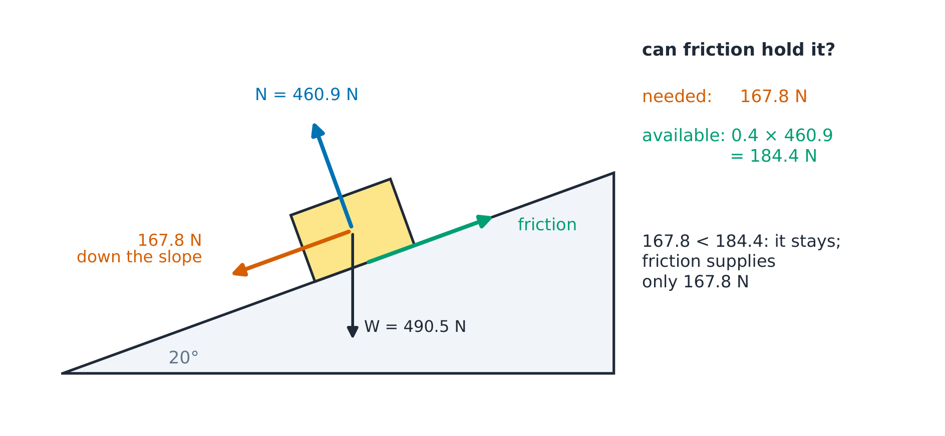
The reaction tilts at most arctan(μs) from the normal — on the edge at impending slipFriction needs 167.8 N of the 184.4 N available, so the block stays put.
Worked example 1 (the incline, and the classic comparison). A 50 kg block on a
20° incline ($\mu_s = 0.4$). Weight component down the slope:
$490.5\sin 20^{\circ} = 167.8$ N; available friction: $0.4 \times 490.5\cos 20^{\circ}
= 184.4$ N. Because $167.8 < 184.4$, the block stays — and the friction force actually
acting is only 167.8 N, not 184.4 N. Friction takes what it needs, never what it could
supply. The steepest no-slip angle follows at once: $\tan^{-1}(0.4) = 21.8°$, just
above 20° — the margin is real but thin.
Worked example 2 (tip or slide, escalated). A crate 0.5 m wide and 1.0 m tall,
mass 40 kg ($W = 392.4$ N), $\mu_s = 0.5$, is pulled horizontally at its top edge.
Sliding needs $P_{slip} = \mu_s W = 0.5 \times 392.4 = 196.2$ N. Tipping about the
front bottom edge balances the pull against the weight's moment:
$P_{tip} \times 1.0 = 392.4 \times 0.25$, so $P_{tip} = 98.1$ N. The smaller one
happens first: the crate tips at 98.1 N, well before any sliding. The design
lesson: tall crates on grippy floors tip; low crates on slippery floors slide —
pull low and the same crate slides instead.
Common mistakes. Setting $F = \mu N$ always: that is the limit; equilibrium sets
the actual force, and only impending slip reaches the limit. Getting the would-be
motion's direction wrong — friction opposes the motion that would occur, not any
motion you can imagine. Comparing $P$ values without checking which failure they
belong to.
Summary: friction self-adjusts up to $\mu_s N$; compare needed against available;
the cone angle $\tan^{-1}\mu_s$ is the steepest self-locking tilt; tip-versus-slide
compares two pulls and takes the smaller.
coefficient of static friction/ˌkəʊɪˈfɪʃənt ɒv ˈstætɪk ˈfrɪkʃn/
静摩擦系数
jìng mó cā xì shù
coefficient of kinetic friction/ˌkəʊɪˈfɪʃənt ɒv kɪˈnetɪk ˈfrɪkʃn/
动摩擦系数
dòng mó cā xì shù
impending slip/ɪmˈpendɪŋ slɪp/
临界滑动
lín jiè huá dòng
1.8
形心与分布载荷
English
Snow piles deeper at mid-span than at the eaves — the beam below does not feel a
point, it feels a shape. Engineering answers with one move: replace the shape by its
total at its balance point, and every earlier tool applies unchanged.
A distributed load 分布载荷 spreads force over a length or area (N/m, N/m²). A
centroid 形心 is the load's balance point: the whole distribution can be replaced
by its resultant — total magnitude acting at the centroid.
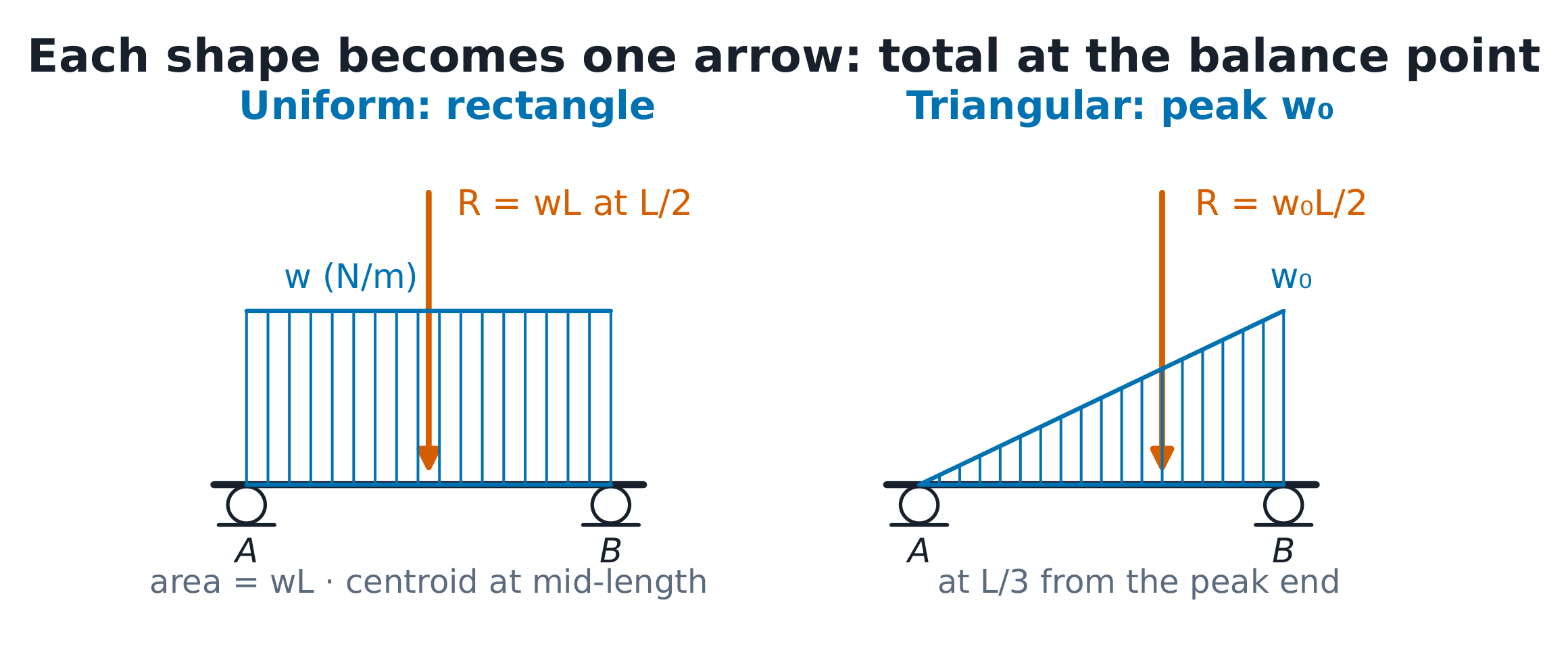
Rectangle (uniform $w$ over length $L$): $R = wL$ at the midpoint, $L/2$.
Triangle (peak $w_{0}$ at one end over $L$): $R = w_{0}L/2$ at $L/3$ from the peak
end.
$$\Sigma M:\ \text{moment of the resultant} = \text{moment of the distribution}$$
Each shape becomes one arrow: total at the balance point
Deriving the triangle's centroid. A strip at $x$ from the peak has width
proportional to $x$, so $\bar{x} = \int x \cdot (w_0 x/L)\,dx \,/\, \int (w_0 x/L)\,dx
= 2L/3$ from the peak — the one-third rule, now with its origin visible.
Worked example 1 (the triangular beam). A triangular load rises from zero to
6 kN/m over 4 m on a simply supported beam. Total: $R = 6 \times 4/2 = 12$ kN acting
at $4/3 = 1.333$ m from the high end. Reactions follow from two moment equations
exactly as for a point load. When a uniform and a triangular load share a beam,
replace each by its resultant and sum — the replacement is exact, not an
approximation.
Worked example 2 (two shapes, machine-verified, escalated). A 6 m beam carries
a uniform 2 kN/m over the first 3 m and a triangle rising to 4 kN/m over the last 3 m.
Resultants: $R_1 = 6$ kN at 1.5 m from A; $R_2 = 6$ kN at 5 m from A. Moments about
A: $R_B \times 6 = 6 \times 1.5 + 6 \times 5 = 39$, so $R_B = 6.5$ kN and
$R_A = 5.5$ kN. Check about B: $5.5 \times 6 = 33 = 27 + 6$ ✓ (machine-verified).
With this the course closes its loop: loads reduce to resultants, resultants enter
free-body diagrams, and the three equilibrium equations finish the job.
Common mistakes. Placing the triangular resultant at the geometric middle — it
sits $L/3$ from the peak end, always. Splitting a trapezoid with the wrong peak ends.
Treating the replacement as approximate: it is exact.
Summary: each shape becomes its total at its centroid — $wL$ at $L/2$, $w_0L/2$ at $L/3$ from the peak — then unit 1.5 finishes, exactly.