Skip to content · ⁨ข้ามไปยังเนื้อหา⁩

Alternating currents · ⁨กระแสสลับ⁩

A-Level Physics · ⁨Physics A-Level⁩ · Topic 21 · ⁨หัวข้อ 21⁩

Video lesson for this topic · ⁨บทเรียนวิดีโอสำหรับหัวข้อนี้⁩ Open the video page · ⁨เปิดหน้าวิดีโอ⁩
11:18

กระแสสลับ

ไฟฟ้าในผนังบ้านของคุณมีความไม่เสถียร ห้าสิบครั้งต่อวินาที — หรือบางทีหกสิบครั้ง — มันจะกลับทิศทาง กระแสพุ่งไปทางหนึ่ง แล้วอีกทางหนึ่ง นี่คือ...

English narration · English + 中文 subtitles burned in · ⁨การบรรยายภาษาอังกฤษ · คำบรรยายภาษาอังกฤษ + 中文 ลอยตัวบนภาพ⁩

21.1

Alternating current basics · ⁨หลักการของกระแสสลับ⁩

Syllabus · ⁨หลักสูตร⁩
English
  1. understand and use the terms period, frequency and peak value as applied to an alternating current or voltage
  2. use equations of the form $x = x_0 \sin \omega t$ representing a sinusoidally alternating current or voltage
  3. recall and use the fact that the mean power in a resistive load is half the maximum power for a sinusoidal alternating current
  4. distinguish between root-mean-square (r.m.s.) and peak values and recall and use $I_{\text{r.m.s.}} = I_0 / \sqrt{2}$ and $V_{\text{r.m.s.}} = V_0 / \sqrt{2}$ for a sinusoidal alternating current
ไทย
  1. เข้าใจและใช้พจน์ รอบ (period), ความถี่ (frequency) และ ค่าสูงสุด (peak value) กับ กระแสสลับ (alternating current) หรือแรงดันไฟฟ้า
  2. ใช้สมการรูปแบบ $x = x_0 \sin \omega t$ ที่แสดงถึงกระแสสลับหรือแรงดันไฟฟ้าแบบไซน์ (sinusoidal alternating current or voltage)
  3. จำและใช้ข้อเท็จจริงว่า กำลังไฟเฉลี่ย (mean power) ในโหลดตัวต้านทานเป็นครึ่งหนึ่งของกำลังไฟสูงสุดสำหรับกระแสสลับแบบไซน์
  4. แยกแยะระหว่าง ค่า-root-mean-square (r.m.s.) และ ค่าสูงสุด (peak values) และจำและใช้ $I_{\text{r.m.s.}} = I_0 / \sqrt{2}$ และ $V_{\text{r.m.s.}} = V_0 / \sqrt{2}$ สำหรับกระแสสลับแบบไซน์

Source: Cambridge International syllabus · ⁨แหล่งที่มา: หลักสูตร Cambridge International⁩

English

An alternating current 交流电 (a.c.) keeps reversing direction. Mains supply is sinusoidal a.c.: $I$ or $V$ follows a sine wave in time:

$$I = I_{0} \sin (\omega t), \qquad V = V_{0} \sin (\omega t).$$

(For a purely resistive load the voltage 电压 and current 电流 are in phase, which is the case in this syllabus.)

Key terms

  • period 周期 $T$ — the time for one full cycle. Unit: s.
  • frequency 频率 $f$ — cycles per second; $f = 1/T$. Mains is often $50\ \text{Hz}$ or $60\ \text{Hz}$.
  • angular frequency 角频率 $\omega = 2\pi f = 2\pi/T$.
  • peak value 峰值 $I_{0}$ or $V_{0}$ — the largest value in a cycle (also called the amplitude).
  • peak-to-peak value 峰峰值 $2 I_{0}$ — from $+I_{0}$ to $-I_{0}$. Useful when reading an oscilloscope.

The two-mark definitions. The frequency of an alternating current is the number of complete cycles per unit time (say "per second" or "per unit time", and "complete cycles" or "oscillations"). The period is the time for one complete cycle, and the peak value is the maximum value of the current or voltage during a cycle. Note that the mean value of a sinusoidal current over a cycle is zero, which is exactly why the r.m.s. value is needed to describe it.

Reading the equation. In $V = V_{0} \sin(\omega t)$ the number in front is the peak value and the number multiplying $t$ is $\omega = 2\pi f$; the angle $\omega t$ is in radians 弧度, so set the calculator to radians before evaluating. A supply written with $\cos$ instead of $\sin$ is the same wave starting at its peak rather than at zero.

Worked example. The output of a supply is $V = 320 \sin(100\pi t)$ (volts, seconds). Find the peak value, the frequency, the period and the r.m.s. value, and the first time after $t = 0$ at which $V = 160\ \text{V}$.

Peak $V_{0} = 320\ \text{V}$. $\omega = 100\pi\ \text{rad s}^{-1}$, so $f = \omega/2\pi = 50\ \text{Hz}$ and $T = 1/f = 0.020\ \text{s}$. $V_{\text{r.m.s.}} = 320/\sqrt{2} = 226\ \text{V}$. For $V = 160\ \text{V}$: $\sin(100\pi t) = 0.5$, so $100\pi t = \pi/6$ and $t = 1/600 = 1.7 \times 10^{-3}\ \text{s}$. (For $V = 18\cos(40\pi t)$ the same reading gives $V_{0} = 18\ \text{V}$, $f = 20\ \text{Hz}$, $T = 50\ \text{ms}$, and a sketch that starts at $+18\ \text{V}$.)

Reading a CRO trace

Same as for any wave (Topic 7), using a cathode-ray oscilloscope 示波器:

  • horizontal divisions × time-base 时基 → period $T$, so $f = 1/T$.
  • vertical divisions × $y$-gain → peak voltage $V_{0}$ (measure centre to peak, or peak-to-peak then halve).
ไทย
สถานีไฟฟ้าแรงสูงพร้อมหม้อแปลง
หม้อแปลงในสถานีแปลงไฟฟ้าช่วยเพิ่มหรือลดแรงดันสลับ

กระแสสลับ (a.c.) จะกลับทิศทางตลอดเวลา การจ่ายไฟจากสายส่งหลักเป็น a.c. แบบไซน์: $I$ หรือ $V$ มีรูปแบบเป็นคลื่นไซน์ตามเวลา:

$$I = I_{0} \sin (\omega t), \qquad V = V_{0} \sin (\omega t).$$

(สำหรับโหลดแบบต้านทานบริสุทธิ์ แรงดัน และ กระแส จะมีเฟสเดียวกัน ซึ่งเป็นกรณีตามหลักสูตรนี้)

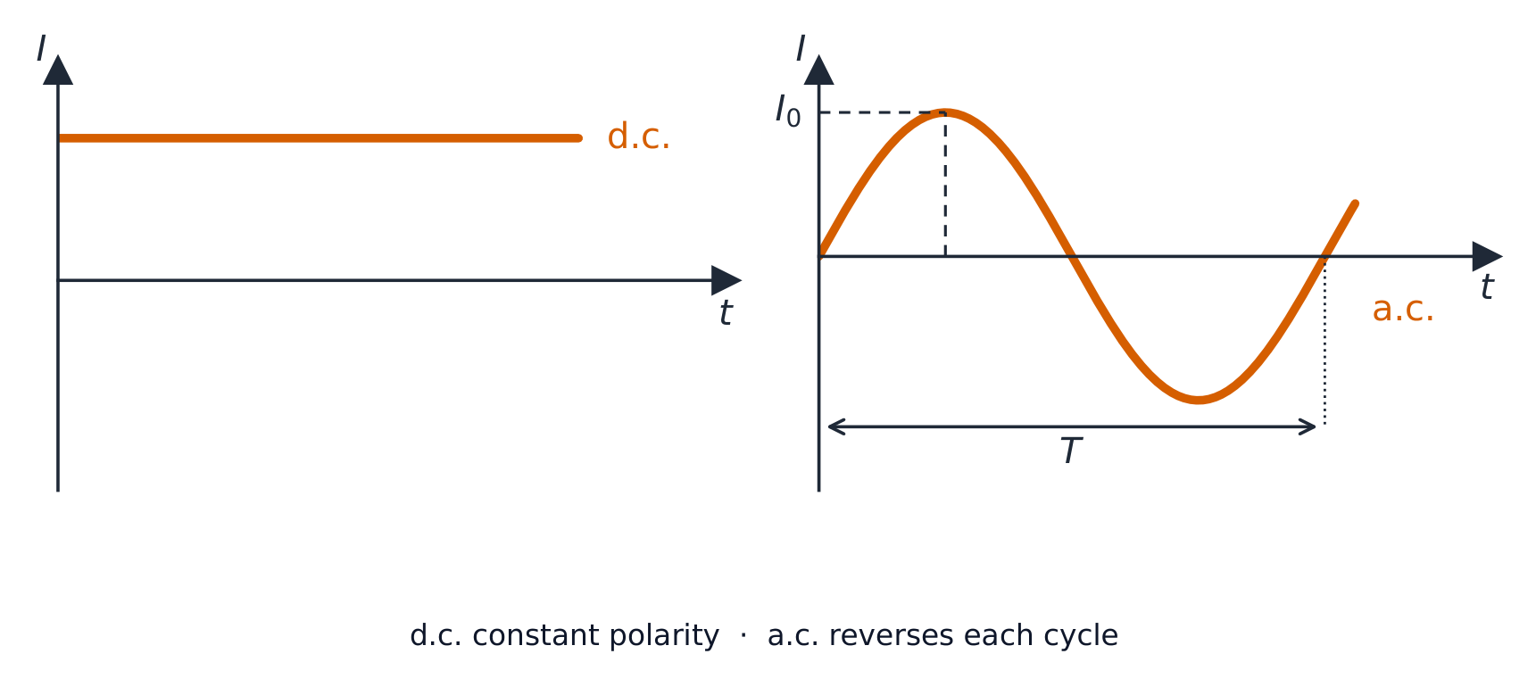
กราฟสองแบบระหว่างกระแส-เวลา: เส้นแนวนอนคงที่สำหรับกระแสตรง, และคลื่นไซน์ของกระแสสูงสุด I0 และรอบ T สำหรับกระแสสลับ
การเปรียบเทียบกระแสตรงที่คงที่กับกระแสสลับแบบไซน์ที่มีค่าสูงสุด $I_0$ และคาบ $T$

คำศัพท์สำคัญ

  • คาบ $T$ — เวลาที่ใช้สำหรับการครบหนึ่งรอบเต็ม หน่วย: วินาที (s)
  • ความถี่ $f$ — จำนวนรอบต่อนาที; $f = 1/T$. การจ่ายไฟจากสายส่งหลักมักจะเป็น $50\ \text{Hz}$ หรือ $60\ \text{Hz}$
  • ความถี่เชิงมุม $\omega = 2\pi f = 2\pi/T$
  • ค่าสูงสุด $I_{0}$ หรือ $V_{0}$ — ค่าที่ใหญ่ที่สุดในหนึ่งรอบ (เรียกว่า ความสูงด้วย)
  • giá trị đỉnh-đỉnh $2 I_{0}$ — từ $+I_{0}$ đến $-I_{0}$. Hữu ích khi đọc máy hiện thị sóng.

นิยามที่ 2 คะแนน. ความถี่ของกระแสสลับคือจำนวนรอบเต็มต่อหน่วยเวลา (พูดว่า "ต่อนาที" หรือ "ต่อหน่วยเวลา" และ "รอบเต็ม" หรือ "การสั่น") คาบคือเวลาสำหรับการครบหนึ่งรอบเต็ม, และ ค่าสูงสุดคือค่าสูงสุดของกระแสหรือแรงดันในช่วงหนึ่งรอบ หมายเหตุว่า ค่าเฉลี่ย ของกระแสแบบไซน์ตลอดหนึ่งรอบเป็น ศูนย์, ซึ่งนี่คือเหตุผลที่จำเป็นต้องใช้ค่า r.m.s. เพื่ออธิบายมัน

Đọc phương trình. Trong $V = V_{0} \sin(\omega t)$, số đứng trước là giá trị đỉnh và số nhân với $t$ là $\omega = 2\pi f$; góc $\omega t$ tính bằng radian, vì vậy hãy đặt máy tính ở chế độ radian trước khi tính toán. Một nguồn điện viết với $\cos$ thay vì $\sin$ là cùng một sóng bắt đầu từ đỉnh thay vì từ không.

**ตัวอย่างวิธีทำ.**เอาต์พุตของการจ่ายไฟคือ $V = 320 \sin(100\pi t)$ (โวลต์, วินาที) หา ค่าสูงสุด, ความถี่, คาบ และค่า r.m.s.,以及我第一次ใน $t = 0$之后 $V = 160\ \text{V}$发生的时间。

ค่าสูงสุด $V_{0} = 320\ \text{V}$. $\omega = 100\pi\ \text{rad s}^{-1}$, ดังนั้น $f = \omega/2\pi = 50\ \text{Hz}$ และ $T = 1/f = 0.020\ \text{s}$. $V_{\text{r.m.s.}} = 320/\sqrt{2} = 226\ \text{V}$. สำหรับ $V = 160\ \text{V}$: $\sin(100\pi t) = 0.5$, ดังนั้น $100\pi t = \pi/6$ และ $t = 1/600 = 1.7 \times 10^{-3}\ \text{s}$. (สำหรับ $V = 18\cos(40\pi t)$ การอ่านค่าเดียวกันจะได้ $V_{0} = 18\ \text{V}$, $f = 20\ \text{Hz}$, $T = 50\ \text{ms}$, และภาพร่างที่เริ่มต้นที่ $+18\ \text{V}$)

การอ่านเทรสจากเครื่องวัดสัญญาณไฟฟ้า

เหมือนกับการอ่านคลื่นใดๆ (หัวข้อ 7), โดยใช้ ออสซิลโลสโคปrorsay: cathode-ray oscilloscope:

  • จำนวนช่องแนวนอน × ฐานเวลา → คาบ $T$, ดังนั้น $f = 1/T$
  • จำนวนช่องแนวตั้ง × $y$-เกน → แรงดันสูงสุด $V_{0}$ (วัดจากกึ่งกลางไปยังยอด, หรือวัดสูงสุดถึงสูงสุดแล้วหารสอง)
Explore · ⁨สำรวจ⁩

Alternating current · ⁨กระแสไฟฟ้าสลับ⁩

I = a sin(bt)

AC is a sine wave — amplitude is the peak, b sets the frequency. · ⁨AC เป็นคลื่น ไซน์ — แอมพลิจูดคือจุดสูงสุด, b กำหนดความถี่⁩

Vocabulary · ⁨คำศัพท์⁩ Train · ⁨ฝึกฝน⁩
English ไทย
cathode-ray oscilloscope/ˈkæθəʊd reɪ ɒˈsɪləskəʊp/ ออสซิลโลสโคปรังสีแคโทด
time-base/taɪm beɪs/ ฐานเวลา
21.1

Power delivered to a resistor · ⁨กำลังไฟที่ส่งให้กับตัวต้านทาน⁩

English

For a resistive load $R$, the instant power 功率 is $P(t) = I(t)^{2} R$. With $I = I_{0}\sin(\omega t)$:

$$P(t) = I_{0}^{2} R \sin^{2}(\omega t).$$

This is always positive, with peak $I_{0}^{2} R$ and minimum zero, oscillating at twice the frequency of $I$. The mean of $\sin^{2}(\omega t)$ over a cycle is $\tfrac{1}{2}$, so the average power is

$$\langle P \rangle = \tfrac{1}{2} I_{0}^{2} R = \tfrac{1}{2} P_{\text{peak}}.$$

Average a.c. power in a resistor is half the peak power.

"Show by calculation that the mean power is half the peak power." A supply of peak value $12\ \text{V}$ drives a $680\ \Omega$ resistor. Peak power: $P_{0} = V_{0}^{2}/R = 12^{2}/680 = 0.212\ \text{W}$, the instantaneous power at the moment the voltage is at its peak. Mean power: use the r.m.s. value, $V_{\text{r.m.s.}} = 12/\sqrt{2} = 8.49\ \text{V}$, so $\langle P \rangle = V_{\text{r.m.s.}}^{2}/R = 8.49^{2}/680 = 0.106\ \text{W}$, exactly half. The two calculations must be shown separately; writing "$\tfrac{1}{2}$ of $0.212$" scores nothing, because that is the thing being shown. The $\tfrac{1}{2}$ is $(1/\sqrt{2})^{2}$: squaring the r.m.s. factor.

ไทย

สำหรับโหลดแบบต้านทาน $R$, กำลัง ทันทีคือ $P(t) = I(t)^{2} R$. เมื่อมี $I = I_{0}\sin(\omega t)$:

กำลังในตัวต้านทานมีการผันแปร; ค่าเฉลี่ยของมันคือครึ่งหนึ่งของกำลังสูงสุด
$$P(t) = I_{0}^{2} R \sin^{2}(\omega t).$$

สิ่งนี้จะเป็นบวกเสมอ โดยมีค่าสูงสุด $I_{0}^{2} R$ และค่าต่ำสุดเป็นศูนย์, สั่นที่ความถี่สองเท่าของ $I$. ค่าเฉลี่ยของ $\sin^{2}(\omega t)$ ตลอดหนึ่งรอบคือ $\tfrac{1}{2}$, ดังนั้น กำลังเฉลี่ย คือ

$$\langle P \rangle = \tfrac{1}{2} I_{0}^{2} R = \tfrac{1}{2} P_{\text{peak}}.$$

กำลังสลับเฉลี่ยในตัวต้านทานคือ ครึ่งหนึ่งของกำลังสูงสุด

"แสดงด้วยการคำนวณว่ากำลังเฉลี่ยเป็นครึ่งหนึ่งของกำลังสูงสุด" การจ่ายไฟที่มีค่าสูงสุด $12\ \text{V}$ ขับเคลื่อนตัวต้านทาน $680\ \Omega$. กำลังสูงสุด: $P_{0} = V_{0}^{2}/R = 12^{2}/680 = 0.212\ \text{W}$, ซึ่งเป็นกำลังทันทีในขณะที่แรงดันอยู่ที่จุดสูงสุด. กำลังเฉลี่ย: ใช้ค่า r.m.s., $V_{\text{r.m.s.}} = 12/\sqrt{2} = 8.49\ \text{V}$, ดังนั้น $\langle P \rangle = V_{\text{r.m.s.}}^{2}/R = 8.49^{2}/680 = 0.106\ \text{W}$, พอดีครึ่งหนึ่ง. การคำนวณทั้งสองต้องแสดงแยกกัน; การเขียนว่า "$\tfrac{1}{2}$ ของ $0.212$" ไม่ได้คะแนน, เพราะนั่นคือสิ่งที่ต้องการพิสูจน์. การ $\tfrac{1}{2}$ คือ $(1/\sqrt{2})^{2}$: การยกกำลังสองของปัจจัย r.m.s.

Vocabulary · ⁨คำศัพท์⁩ Train · ⁨ฝึกฝน⁩
English ไทย
power/ˈpaʊə/ กำลัง
21.1

Root-mean-square (r.m.s.) values · ⁨ค่า root-mean-square (r.m.s.)⁩

English

The r.m.s. current $I_{\text{r.m.s.}}$ is the steady direct current that would give the same average power in the same resistance 电阻 $R$. From $\langle P \rangle = I_{\text{r.m.s.}}^{2} R = \tfrac{1}{2} I_{0}^{2} R$:

$$I_{\text{r.m.s.}} = \frac{I_{0}}{\sqrt{2}}, \qquad V_{\text{r.m.s.}} = \frac{V_{0}}{\sqrt{2}}.$$

Worked example. An a.c. supply has a peak voltage of $12\ \text{V}$. Find its r.m.s. voltage.

$$V_{\text{r.m.s.}} = \frac{V_{0}}{\sqrt{2}} = \frac{12}{\sqrt{2}} \approx 8.5\ \text{V}.$$

The $\sqrt{2}$ comes from the name root-mean-square 均方根: $I_{\text{r.m.s.}} = \sqrt{\langle I^{2} \rangle}$ and $\langle \sin^{2}\rangle = \tfrac{1}{2}$. (Only the sinusoidal case is needed.)

The two-mark definition. The r.m.s. value of an alternating current is the value of the direct (steady) current that would dissipate the same (mean) power in the same resistor. "By reference to the heating effect" means exactly this sentence: same resistor, same power (or same heating), direct current. A definition that only says "$I_{0}/\sqrt{2}$" scores nothing, because that formula is true only for a sine wave.

Worked example (non-sinusoidal). A current through a resistor is $+2.0\ \text{A}$ for the first half of each cycle and $-1.0\ \text{A}$ for the second half, a square wave 方波. Find its r.m.s. value and the mean power in a $10\ \Omega$ resistor.

Square the current: $4.0\ \text{A}^{2}$ for half the time and $1.0\ \text{A}^{2}$ for the other half, so the mean square is $(4.0 + 1.0)/2 = 2.5\ \text{A}^{2}$ and $I_{\text{r.m.s.}} = \sqrt{2.5} = 1.6\ \text{A}$. Mean power $= I_{\text{r.m.s.}}^{2} R = 2.5 \times 10 = 25\ \text{W}$. The sign of the current does not matter to the heating (it is squared away), and $I_{0}/\sqrt{2}$ would have given the wrong answer, $1.4\ \text{A}$: that shortcut is for sine waves only.

Why r.m.s. matters

Quoted a.c. values are r.m.s. values. "$230\ \text{V}$ mains" means $V_{\text{r.m.s.}} = 230\ \text{V}$, with peak $V_{0} = 230\sqrt{2} \approx 325\ \text{V}$. Components must be rated for the peak, not the r.m.s. Average power then takes the d.c. form:

$$\langle P \rangle = I_{\text{r.m.s.}}^{2} R = V_{\text{r.m.s.}}^{2} / R = V_{\text{r.m.s.}} I_{\text{r.m.s.}}.$$

Worked example. A heater of resistance $50\ \Omega$ is connected to the $230\ \text{V}$ r.m.s. mains. Find the r.m.s. current and the average power dissipated.

$$I_{\text{r.m.s.}} = \frac{V_{\text{r.m.s.}}}{R} = \frac{230}{50} = 4.6\ \text{A}, \qquad \langle P \rangle = V_{\text{r.m.s.}} I_{\text{r.m.s.}} = 230 \times 4.6 \approx 1.1 \times 10^{3}\ \text{W}.$$

Worked example. A sinusoidal supply of r.m.s. value $4.2\ \text{V}$ and frequency $50\ \text{kHz}$ is connected across a $150\ \Omega$ resistor. Find the peak current, the mean power, and write down an equation for the current.

$V_{0} = 4.2\sqrt{2} = 5.9\ \text{V}$, so $I_{0} = V_{0}/R = 5.9/150 = 0.040\ \text{A}$ (or $I_{\text{r.m.s.}} = 4.2/150 = 0.028\ \text{A}$ and then $\times\sqrt{2}$). Mean power $= V_{\text{r.m.s.}}^{2}/R = 4.2^{2}/150 = 0.12\ \text{W}$. With $\omega = 2\pi f = 2\pi \times 5.0 \times 10^{4} = 3.1 \times 10^{5}\ \text{rad s}^{-1}$: $I = 0.040 \sin(3.1 \times 10^{5} t)$ (amps, seconds). Keep the two families apart: peak values go into the equation and into component ratings; r.m.s. values go into power.

ไทย

กระแส r.m.s. $I_{\text{r.m.s.}}$ คือ กระแสตรงคงที่ ที่จะให้กำลังเฉลี่ยเท่ากันใน ความต้านทาน เดียวกัน $R$. จาก $\langle P \rangle = I_{\text{r.m.s.}}^{2} R = \tfrac{1}{2} I_{0}^{2} R$:

$$I_{\text{r.m.s.}} = \frac{I_{0}}{\sqrt{2}}, \qquad V_{\text{r.m.s.}} = \frac{V_{0}}{\sqrt{2}}.$$
แรงดันไฟฟ้ากระแสสลับรูปไซน์ที่มีค่าสูงสุด V0, มีเส้นประแนวนอนที่ V0 หารด้วยราก 2 เพื่อแสดงค่า r.m.s. — ระดับกระแสตรงที่ให้ความร้อนเฉลี่ยเท่ากัน
ค่า r.m.s. คือระดับ d.c. ที่คงที่ ($V_0/\sqrt{2}$) ที่ส่งกำลังเฉลี่ยเท่ากับ a.c.

ตัวอย่างวิธีทำ. การจ่ายไฟ a.c. มีแรงดันสูงสุด $12\ \text{V}$ หาแรงดัน r.m.s. ของมัน

$$V_{\text{r.m.s.}} = \frac{V_{0}}{\sqrt{2}} = \frac{12}{\sqrt{2}} \approx 8.5\ \text{V}.$$

$\sqrt{2}$ มาจากชื่อ root-mean-square: $I_{\text{r.m.s.}} = \sqrt{\langle I^{2} \rangle}$ และ $\langle \sin^{2}\rangle = \tfrac{1}{2}$. (ต้องใช้เฉพาะกรณีแบบไซน์)

นิยามสำหรับ 2 คะแนน. ค่า r.m.s. ของกระแสสลับ คือ ค่าของกระแสตรง (กระแสคงที่) ที่จะทำให้เกิดกำลังความร้อนเท่ากันในตัวต้านทานเดียวกัน. "การอ้างอิงถึงผลของการทำความร้อน" หมายถึงประโยคนี้เป๊ะๆ: ตัวต้านทานเดียวกัน, กำลังเท่ากัน (หรือความร้อนเท่ากัน), กระแสตรง. นิยามที่บอกแค่ว่า "$I_{0}/\sqrt{2}$" จะไม่มีคะแนนเลย เพราะสูตรนั้นเป็นจริงเฉพาะคลื่นไซน์เท่านั้น.

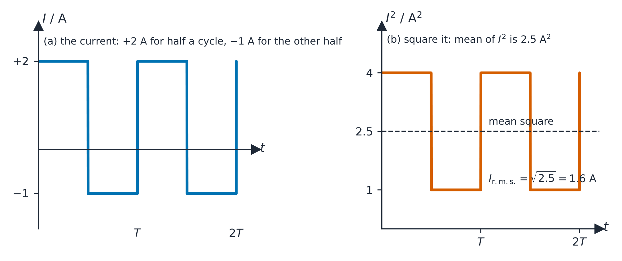
กราฟสองเส้น: กระแสคลื่นสี่เหลี่ยมที่เป็นบวก 2 แอมป์ครึ่งหนึ่งและลบ 1 แอมป์อีกครึ่งหนึ่ง, และกำลังสองของมันคือ 4 และ 1, โดยมีค่าเฉลี่ยกำลังสองอยู่ที่ 2.5 ชี้ไว้; รากของค่าเฉลี่ยกำลังสองคือ 1.6 แอมป์
ราก-เฉลี่ย-กำลังสอง, อ่านตามตัวอักษร: ยกกำลังสองกระแส, หาค่าเฉลี่ยของกำลังสองตลอดรอบ, แล้วถอดรากที่สอง. สำหรับกระแสที่ไม่ใช่รูปทรงคลื่นไซน์ นี่คือวิธีเดียว; $I_0/\sqrt{2}$ ใช้ได้กับคลื่นไซน์เท่านั้น

ตัวอย่างวิธีทำ (ไม่ใช่วิธีกำหนดรูปแบบคลื่นไซน์). กระแสไหลผ่านตัวต้านทานมีค่า $+2.0\ \text{A}$ ในครึ่งแรกของแต่ละรอบ และ $-1.0\ \text{A}$ ในครึ่งหลัง, ซึ่งเป็น คลื่นสี่เหลี่ยม. จงหาค่า r.m.s. และกำลังเฉลี่ยในตัวต้านทานขนาด $10\ \Omega$

ยกกำลังสองกระแส: $4.0\ \text{A}^{2}$ เป็นเวลาครึ่งหนึ่ง และ $1.0\ \text{A}^{2}$ เป็นเวลาอีกครึ่งหนึ่ง, ดังนั้นค่าเฉลี่ยกำลังสองคือ $(4.0 + 1.0)/2 = 2.5\ \text{A}^{2}$ และ $I_{\text{r.m.s.}} = \sqrt{2.5} = 1.6\ \text{A}$. กำลังเฉลี่ย $= I_{\text{r.m.s.}}^{2} R = 2.5 \times 10 = 25\ \text{W}$. สัญญาณของกระแสไม่สำคัญต่อการทำความร้อน (เพราะถูกยกกำลังสองไปหมดแล้ว), และ $I_{0}/\sqrt{2}$ จะให้คำตอบผิด, $1.4\ \text{A}$: ทางลัดนี้ใช้ได้เฉพาะคลื่นไซน์เท่านั้น.

ทำไมต้อง r.m.s.

ค่า a.c. ที่ระบุมาคือค่า r.m.s. "$230\ \text{V}$ ไฟฟ้าจาก电网" หมายความว่า $V_{\text{r.m.s.}} = 230\ \text{V}$, ซึ่งค่าสูงสุดจะอยู่ที่ $V_{0} = 230\sqrt{2} \approx 325\ \text{V}$. ส่วนประกอบต้องทนต่อค่าสูงสุด ไม่ใช่ค่า r.m.s. กำลังเฉลี่ยจึงใช้รูปแบบ d.c. ดังนี้:

$$\langle P \rangle = I_{\text{r.m.s.}}^{2} R = V_{\text{r.m.s.}}^{2} / R = V_{\text{r.m.s.}} I_{\text{r.m.s.}}.$$

ตัวอย่างวิธีทำ. เครื่องทำความร้อนมีความต้านทาน $50\ \Omega$ เชื่อมต่อกับแหล่งจ่ายไฟ mains r.m.s. ขนาด $230\ \text{V}$. จงหากระแส r.m.s. และกำลังเฉลี่ยที่สูญเสีย

$$I_{\text{r.m.s.}} = \frac{V_{\text{r.m.s.}}}{R} = \frac{230}{50} = 4.6\ \text{A}, \qquad \langle P \rangle = V_{\text{r.m.s.}} I_{\text{r.m.s.}} = 230 \times 4.6 \approx 1.1 \times 10^{3}\ \text{W}.$$

ตัวอย่างวิธีทำ. แหล่งจ่ายรูปทรงคลื่นไซน์ที่มีค่า r.m.s. เท่ากับ $4.2\ \text{V}$ และความถี่ $50\ \text{kHz}$ เชื่อมต่อข้ามตัวต้านทานขนาด $150\ \Omega$. จงหากระแสสูงสุด, กำลังเฉลี่ย, และเขียนสมการสำหรับกระแส

$V_{0} = 4.2\sqrt{2} = 5.9\ \text{V}$, ดังนั้น $I_{0} = V_{0}/R = 5.9/150 = 0.040\ \text{A}$ (หรือ $I_{\text{r.m.s.}} = 4.2/150 = 0.028\ \text{A}$ แล้วตามด้วย $\times\sqrt{2}$). กำลังเฉลี่ย $= V_{\text{r.m.s.}}^{2}/R = 4.2^{2}/150 = 0.12\ \text{W}$. เมื่อใช้ $\omega = 2\pi f = 2\pi \times 5.0 \times 10^{4} = 3.1 \times 10^{5}\ \text{rad s}^{-1}$: จะได้ $I = 0.040 \sin(3.1 \times 10^{5} t)$ (แอมป์, วินาที). Keep the two families apart: ค่าสูงสุดนำไปใส่ในสมการและในการกำหนดคุณสมบัติของส่วนประกอบ; ค่า r.m.s. นำไปใช้คำนวณกำลัง

Vocabulary · ⁨คำศัพท์⁩ Train · ⁨ฝึกฝน⁩
English ไทย
root-mean-square/ruːt miːn skweə/ รากที่สองของกำลังสองเฉลี่ย
square wave/skweə weɪv/ คลื่นสี่เหลี่ยม
21.2

Rectification · ⁨การเปลี่ยนกระแสสลับเป็นกระแสตรง (Rectification)⁩

Syllabus · ⁨หลักสูตร⁩
English
  1. distinguish graphically between half-wave and full-wave rectification
  2. explain the use of a single diode for the half-wave rectification of an alternating current
  3. explain the use of four diodes (bridge rectifier) for the full-wave rectification of an alternating current
  4. analyse the effect of a single capacitor in smoothing, including the effect of the values of capacitance and the load resistance
ไทย
  1. แยกแยะระหว่าง การเปลี่ยนรูปครึ่งคลื่น (half-wave) และ การเปลี่ยนรูปเต็มคลื่น (full-wave rectification) แบบกราฟ
  2. อธิบายการใช้ไดโอดเดียวสำหรับการเปลี่ยนรูปครึ่งคลื่นของกระแสสลับ
  3. อธิบายการใช้ไดโอดสี่ตัว (บริดจ์เรกติฟายเออร์, bridge rectifier) สำหรับการเปลี่ยนรูปเต็มคลื่นของกระแสสลับ
  4. วิเคราะห์ผลกระทบของตัวเก็บประจุเดียวในการทำให้เรียบ (smoothing) รวมถึงผลกระทบของค่าความจุและ ความต้านทานโหลด (load resistance)

Source: Cambridge International syllabus · ⁨แหล่งที่มา: หลักสูตร Cambridge International⁩

English

Rectification 整流 turns an alternating voltage into a one-direction (d.c.-like) voltage, using diodes 二极管 (which conduct in only one direction).

"State what is meant by rectification." The conversion of an alternating current (or voltage) into a direct current (or voltage): one that flows in one direction only, however much it varies. A diode conducts only when it is forward-biased 正向偏置, that is, when its anode (the flat end of the symbol's triangle) is more positive than its cathode (the bar); otherwise it is reverse-biased and behaves like an open switch. Treat it as ideal: zero resistance one way, infinite the other.

Half-wave rectification

A single diode in series with the load passes only the positive half of each cycle; in the negative half the diode is reverse-biased 反向偏置 and no current flows. This is half-wave rectification 半波整流.

Output: positive half-waves with flat zero gaps. The mean output is $V_{0}/\pi \approx 0.32 V_{0}$. Drawback: half the input is wasted and the output is very uneven.

Completing the circuit. "Complete the diagram to produce half-wave rectification" needs one diode in series between the supply and the load, with the triangle pointing the way the output current must flow, and $V_{\text{OUT}}$ taken across the load. If a capacitor is to smooth the output it goes across the load (in parallel); a capacitor in series would block the d.c. altogether.

Full-wave rectification (bridge rectifier)

A bridge rectifier 桥式整流器 uses four diodes arranged so the current through the load always flows the same way, whichever a.c. terminal is positive — full-wave rectification 全波整流. On each half-cycle a different pair of diodes conducts, but the load always sees the same direction.

Explaining the bridge (the standard four-marker). When terminal P is positive, current leaves P, passes through the diode pointing away from P to the top of the load, flows down through the load and returns to Q through the diode pointing towards Q; the other two diodes are reverse-biased and carry nothing. When Q is positive the other pair conducts, but they are arranged so that the current still enters the load at the top: the load current is in the same direction in both half-cycles. Name the diodes in each half-cycle and say which end of the load is positive.

Completing a bridge. Given a bridge with diodes missing, remember the rule for every diode: conventional current flows through it in the direction of the triangle. Both diodes joined to the positive output terminal must point towards it; both joined to the negative output terminal must point away from it. A bridge with a diode the wrong way round either short-circuits the supply on one half-cycle or passes nothing.

Output: a continuous run of positive half-waves (no gaps), at twice the input frequency. The mean output is $2V_{0}/\pi \approx 0.64 V_{0}$ — double the half-wave value. It uses all the input and is smoother and easier to filter.

Drawing the diagrams

  • half-wave: a.c. source — single diode — load $R$, in series.
  • full-wave bridge: four diodes as the arms of a "diamond"; the a.c. input goes to one pair of opposite corners, the load $R$ across the other pair. The diode directions make the load terminals keep the same polarity for either input polarity.

"State the difference between half-wave and full-wave rectification." In half-wave rectification only one half of each input cycle appears at the output and the other half is blocked (the output is zero for half the time); in full-wave rectification both halves appear, one of them inverted, so there are no gaps and the output has twice the input frequency. A sketch should show, for half-wave, positive humps separated by flat zero sections of equal length; for full-wave, positive humps joined at the zero line.

ไทย
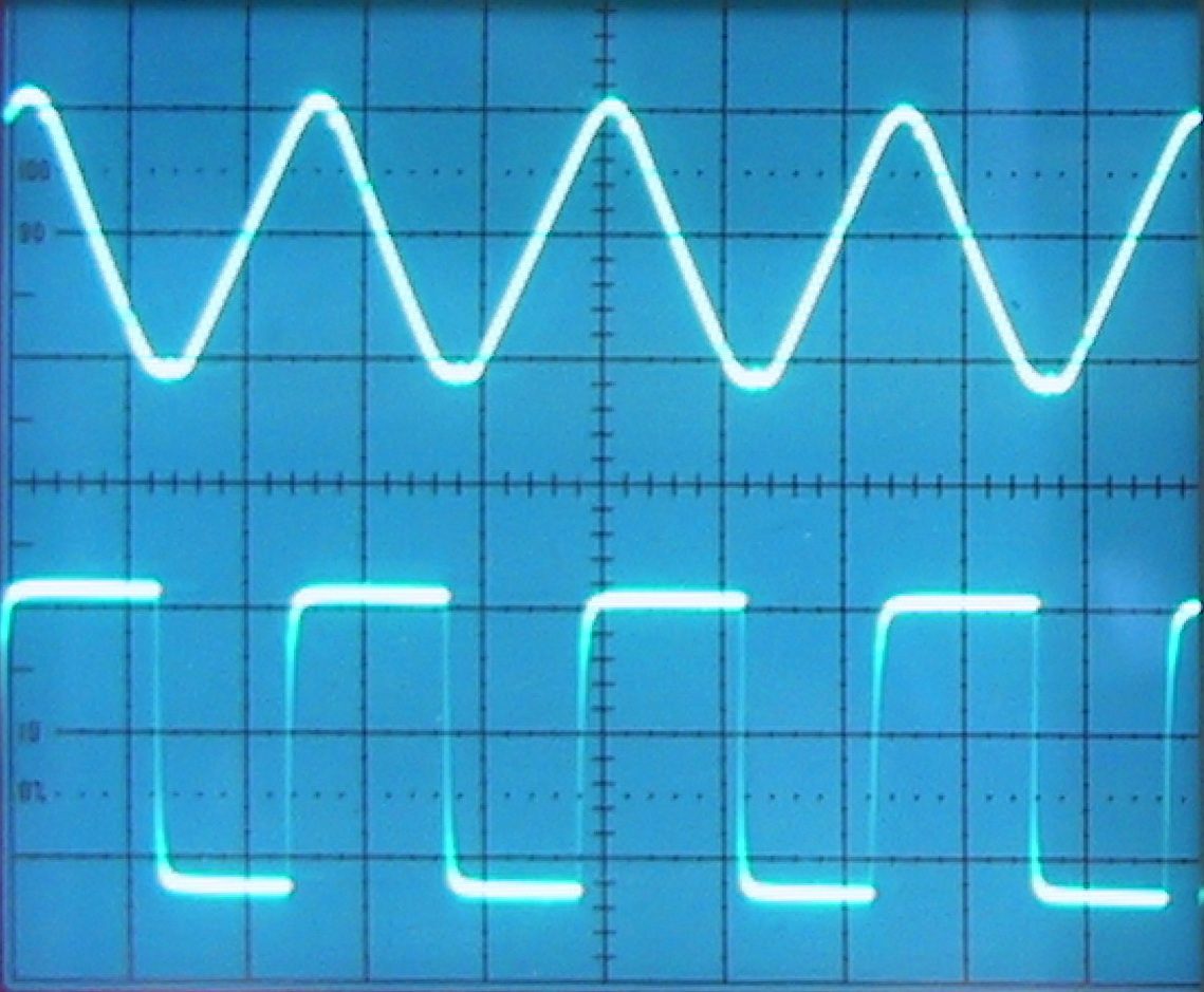
สัญญาณบนหน้าจอออสซิลโลสโคป
ออสซิลโลสโคปแสดงการเปลี่ยนแปลงของแรงดันไฟฟ้าตามเวลา

การเปลี่ยนกระแสสลับเป็นกระแสตรง (Rectification) เปลี่ยนแรงดันสลับให้เป็นแรงดันทิศทางเดียว (คล้าย d.c.) โดยใช้ ไดโอด (ซึ่งนำกระแสได้เพียงทิศทางเดียว)

"ระบุความหมายของการเปลี่ยนกระแสสลับเป็นกระแสตรง (Rectification)." การแปลงกระแสสลับ (หรือแรงดันสลับ) ให้เป็นกระแสตรง (หรือแรงดันตรง):即.current that flows in one direction only, however much it varies. A diode conducts only when it is forward-biased, that is, when its anode (the flat end of the symbol's triangle) is more positive than its cathode (the bar); otherwise it is reverse-biased and behaves like an open switch. Treat it as ideal: zero resistance one way, infinite the other.

การเปลี่ยนกระแสสลับเป็นกระแสแบบครึ่งรอบ (Half-wave rectification)

ไดโอดหนึ่งตัว เชื่อมอนุกรมกับโหลดจะส่งผ่านเพียงครึ่งบวกของแต่ละรอบ; ในครึ่งลบ ไดโอดจะเป็น reverse-biased และไม่มีการไหลของกระแส. นี่คือ half-wave rectification

เอาต์พุต: คลื่นบวกครึ่งรอบพร้อมช่องว่างศูนย์ราบเรียบ. ค่าเฉลี่ยเอาต์พุตคือ $V_{0}/\pi \approx 0.32 V_{0}$. ข้อเสีย: ข้อมูลเข้าครึ่งหนึ่งถูกทิ้งไปและเอาต์พุตไม่สม่ำเสมอมาก

กราฟสองเส้น: แรงดัน-เวลา: อินพุตคือคลื่นไซน์เต็ม; เอาต์พุตเก็บเฉพาะครึ่งบวกพร้อมช่องว่างราบเรียบเมื่อครึ่งลบถูกตัด
在半波整流中,单个二极管只通过正半周期
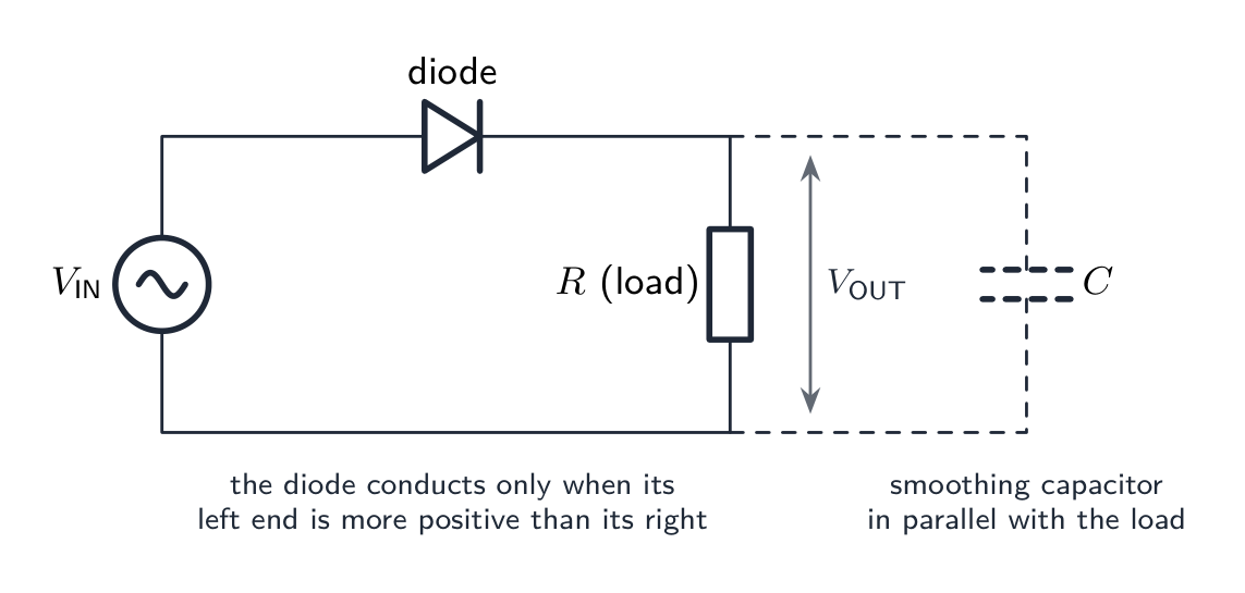
วงจร half-wave rectifier: แหล่งจ่าย a.c., ไดโอดแบบอนุกรม, และตัวต้านทานโหลดที่วัดเอาต์พุต, พร้อมตัวเก็บประจุ smoothing画的ขนานกับโหลด
Half-wave rectifier ที่ข้อสอบขอให้วาด: แหล่งจ่าย, ไดโอด, โหลดแบบอนุกรม, เอาต์พุตข้ามโหลด; ตัวเก็บประจุ smoothing, ถ้าต้องการ, จะวางขนานกับโหลด ไม่เคยวางแบบอนุกรม

การเติมเต็มวงจร. "เติมเต็มแผนภาพเพื่อสร้าง half-wave rectification" ต้องใช้ไดโอดหนึ่งตัวใน แบบอนุกรม ระหว่างแหล่งจ่ายและโหลด, โดยสามเหลี่ยมชี้ไปในทิศทางการไหลของกระแสเอาต์พุต, และ $V_{\text{OUT}}$ วัดข้าม โหลด. หากต้องการใช้ตัวเก็บประจุเพื่อทำให้เอาต์พุตเรียบขึ้น จะวาง ข้ามโหลด (ขนาน); ตัวเก็บประจุแบบอนุกรมจะขัดขวางกระแส d.c. ทั้งหมด

การเปลี่ยนกระแสสลับเป็นกระแสแบบเต็มรอบ (Full-wave rectification) (Bridge rectifier)

Bridge rectifier ใช้ ไดโอดสี่ตัว จัดเรียงเพื่อให้กระแสไหลผ่านโหลดในทิศทางเดิมเสมอ ไม่ว่าขั้ว a.c. ขาไหนจะเป็นบวก — full-wave rectification. ในแต่ละครึ่งรอบ会有不同的两个二极管导通, แต่โหลดจะเห็นทิศทางเดียวกันเสมอ

Four diodes arranged in a diamond between the a.c. input terminals P and Q and the load R; diodes 1 and 2 conduct on one half-cycle, 3 and 4 on the other, so the d.c. output keeps the same polarity
A four-diode bridge sends the load current the same way whichever a.c. terminal is positive

อธิบาย Bridge (มาตรฐาน 4 คะแนน). เมื่อขั้ว P เป็นบวก, กระแสออกจาก P, ผ่านไดโอดที่ชี้ห่างจาก P ไปยัง ด้านบน ของโหลด, ไหล ลง ผ่านโหลด และกลับไปยัง Q ผ่านไดโอดที่ชี้เข้าหา Q; ไดโอดอีกสองตัวจะเป็น reverse-biased และไม่มีการไหลของกระแส. เมื่อ Q เป็นบวก, คู่ที่เหลือจะ导通, แต่จัดวาง έτσιว่ากระแสยังคงเข้าสู่โหลดจากด้านบน: กระแสโหลดอยู่ใน ทิศทางเดียวกัน ทั้งสองครึ่งรอบ. ระบุชื่อไดโอดในแต่ละครึ่งรอบและบอกว่าด้านใดของโหลดเป็นบวก

การต่อวงจรบริดจ์ไดโอด เมื่อมีไดโอดขาดหายไป ให้จำกฎของไดโอดทุกตัว: กระแสไฟแบบคอนเวนชันจะไหลผ่านไดโอดไปในทิศทางเดียวกับสามเหลี่ยม ไดโอดทั้งสองที่ต่อกับขั้ว บวก ของเอาต์พุตต้องชี้เข้าหาขั้วนั้น; ไดโอดทั้งสองที่ต่อกับขั้ว ลบ ของเอาต์พุตต้องชี้ออกจากขั้วนั้น หากไดโอดในบริดจ์ติดกลับด้าน จะทำให้แหล่งจ่ายไฟฟ้าลัดวงจรในช่วงครึ่งรอบหนึ่ง หรือไม่มีการส่งกระแสเลย

เอาต์พุต: เป็นชุดของครึ่งคลื่นบวกต่อเนื่อง (ไม่มีช่วงว่าง) ที่ความถี่เป็น สองเท่าของความถี่อินพุต ค่าเฉลี่ยของเอาต์พุตคือ $2V_{0}/\pi \approx 0.64 V_{0}$ — เป็นสองเท่าของค่าครึ่งคลื่น ใช้พลังงานอินพุตทั้งหมดและมีความเรียบกว่า ทำให้กรองสัญญาณได้ง่ายขึ้น

กราฟแรงดัน-เวลาสองชุด: อินพุตเป็นคลื่นไซน์เต็ม; เอาต์พุตเป็นชุดของลูกศรบวกต่อเนื่องไม่มีช่วงว่าง ที่ความถี่เป็นสองเท่าของอินพุต
ในการปรับกระแสสลับให้เป็นกระแสตรงแบบเต็มคลื่น ทุกครึ่งรอบจะถูกใช้ ทำให้เกิดชุดของลูกศรบวกต่อเนื่อง

การวาดแผนภาพ

  • ครึ่งคลื่น: แหล่งจ่าย a.c. — ไดโอดตัวเดียว —โหลด $R$, ต่ออนุกรมกัน
  • บริดจ์เต็มคลื่น: ไดโอดสี่ตัวเป็นแขนของรูป "เพชร"; อินพุต a.c. เข้าคู่มุมตรงข้ามหนึ่งคู่ โหลด $R$ เชื่อมข้ามคู่มุมตรงข้ามอีกคู่ ทิศทางของไดโอดทำให้ขั้วโหลดคงความเป็นขั้วเดียวกันไม่ว่า极性อินพุตจะเป็นอย่างไร

"ระบุความแตกต่างระหว่าง HALF-WAVE และ FULL-WAVE RECTIFICATION" ในการปรับกระแสแบบ HALF-WAVE มีเพียง ครึ่งหนึ่งของ รอบอินพุตแต่ละรอบที่ปรากฏที่เอาต์พุต และอีกครึ่งถูกกั้น (เอาต์พุตเป็นศูนย์ครึ่งหนึ่งของเวลา); ใน HALF-WAVE RECTIFICATION ทั้งสองครึ่ง ปรากฏ出来 โดยครึ่งหนึ่งกลับด้าน ดังนั้นจึงไม่มีช่วงว่าง และเอาต์พุตมีความถี่เป็นสองเท่าของอินพุต ภาพร่างควรแสดง สำหรับ HALF-WAVE เป็นลูกศรบวกแยกด้วยส่วนที่เป็นศูนย์ราบยาวเท่ากัน; สำหรับ FULL-WAVE เป็นลูกศรบวกเชื่อมต่อกันที่เส้นศูนย์

Explore · ⁨สำรวจ⁩

Rectifier and smoothing route · ⁨เส้นทางไดโอดและลดคลื่นรบกวน⁩

Watch alternating input become a smoother direct output. · ⁨สังเกตกระแสสลับเข้า就变成了เรียบขึ้นเป็นกระแสตรงออก⁩

Vocabulary · ⁨คำศัพท์⁩ Train · ⁨ฝึกฝน⁩
English ไทย
alternating current/ˈɔːltəneɪtɪŋ ˈkʌrənt/ กระแสสลับ
current/ˈkʌrənt/ 电流的属性
voltage/ˈvəʊltɪdʒ/ แรงดันไฟฟ้า
load/ləʊd/ น้ำหนัก
period/ˈpɪərɪəd/ รอบ
frequency/ˈfriːkwənsi/ ความถี่
angular frequency/ˈæŋɡjʊlə ˈfriːkwənsi/ ความถี่เชิงมุม
peak value/piːk ˈvæljuː/ ค่าสูงสุด
peak-to-peak value/piːk tə piːk ˈvæljuː/ ค่าสูงสุดถึงต่ำสุด
radians/ˈreɪdɪənz/ เรเดียน
resistance/rɪˈzɪstəns/ ความต้านทาน
rectification/ˌrektɪfɪˈkeɪʃn/ การปรับรูปคลื่น
diode/ˈdaɪəʊd/ ไดโอด
forward-biased/ˈfɔːwəd ˈbaɪəst/ ไบয়াส์ด้านหน้า
reverse-biased/rɪˈvɜːs ˈbaɪəst/ ไบয়াส์ด้านหลัง
half-wave rectification/hɑːf weɪv ˌrektɪfɪˈkeɪʃn/ การเปลี่ยนรูปคลื่นครึ่ง
smoothing/ˈsmuːðɪŋ/ การลดคลื่นรบกวน
full-wave rectification/fʊl weɪv ˌrektɪfɪˈkeɪʃn/ การเปลี่ยนรูปคลื่นเต็ม
bridge rectifier/brɪdʒ ˈrektɪfaɪə/ เรกติไฟเออร์แบบสะพาน
21.2

Smoothing with a capacitor · ⁨การปรับความเรียบด้วยตัวเก็บประจุ⁩

English

A rectifier's output is still bumpy. To smooth it, put a capacitor 电容器 $C$ in parallel with the load $R$.

How it works

  • on the rising part of each pulse, the capacitor charges up to near the peak.
  • on the falling part (and any gap), the diodes are reverse-biased, so the capacitor discharges through the load, keeping current flowing. The voltage falls with time constant 时间常数 $RC$ (Topic 19).
  • at the next peak, the capacitor charges again, and the cycle repeats.

The output now sits near the peak with small dips. The size of the dips is the ripple 纹波 (this whole step is called smoothing 平滑).

Worked example. A half-wave rectifier fed from a $50\ \text{Hz}$ supply has a $470\ \mu\text{F}$ capacitor across its $1.2\ \text{k}\Omega$ load 负载. Estimate the fractional fall in the output between peaks, and say how it changes with a bridge rectifier.

The peaks are $T = 1/50 = 20\ \text{ms}$ apart (half-wave: one peak per cycle). The time constant is $RC = (1.2 \times 10^{3})(470 \times 10^{-6}) = 0.56\ \text{s}$. Between peaks the capacitor discharges to $V_{0} e^{-t/RC} = V_{0} e^{-0.020/0.56} = 0.965\,V_{0}$, a fall of about $3.5\%$. With full-wave rectification the peaks are $10\ \text{ms}$ apart, so the fall is only $1.8\%$; doubling the capacitance would halve it again. Because $t \ll RC$ the fall is approximately $V_{0}\, t/(RC)$: the ripple is proportional to the time between peaks and inversely proportional to both $R$ and $C$. (A network of capacitors across the output combines by the rules of Topic 19 before it is used here.)

What reduces the ripple

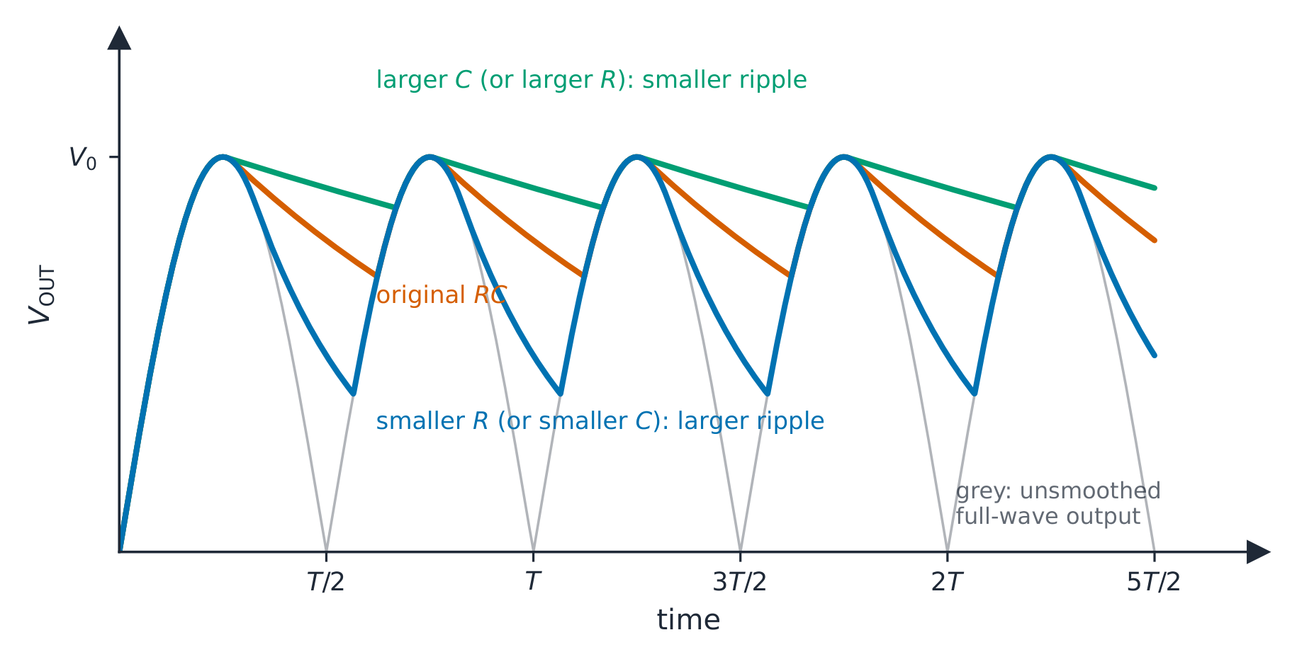
  • larger $C$ → more stored charge → smaller dip between peaks → smaller ripple.
  • larger $R$ → smaller load current → slower discharge → smaller ripple.
  • higher rectified frequency (full-wave is twice the input) → less time to discharge between peaks → smaller ripple.

In short, a large $RC$ compared with the time between peaks gives a smoother output.

Sketching the smoothed output. Draw the unsmoothed humps faintly first. The smoothed curve touches each peak, then falls along a gentle curve (steepest just after the peak) until the next hump rises to meet it, where it turns sharply upwards and follows the hump to the peak. It never falls to zero, and it never rises above the peak. For half-wave rectification the decay has to last through the missing half-cycle as well, so the ripple is about twice that of full-wave for the same $RC$. If the question changes $C$ or $R$, redraw on the same axes: a larger $RC$ hugs the peak line more closely; a smaller $RC$ sags further.

Purpose in summary

The smoothing capacitor reduces the ripple, giving a steadier d.c. voltage suitable for sensitive electronics.

ไทย

เอาต์พุตของเรกติฟายเออร์ยังคงมีลักษณะเป็นคลื่นกระตุก เพื่อปรับให้เรียบ ให้ใส่ ตัวเก็บประจุ $C$ ขนานกับโหลด $R$

หลักการทำงาน

  • ในช่วง ** rising part** ของแต่ละพัลส์ ตัวเก็บประจุจะชาร์จจนใกล้ถึงจุดสูงสุด
  • ในช่วง falling part (และช่วงว่าง) ไดโอดจะ reverse-biased ทำให้ตัวเก็บประจุ คายประจุผ่านโหลด รักษากระแสไหลอยู่ แรงดันจะลดลงตาม time constant $RC$ (หัวข้อ 19)
  • ที่จุดสูงสุดถัดไป ตัวเก็บประจุจะชาร์จอีกครั้ง และวงจรจะซ้ำเดิม

เอาต์พุตตอนนี้จะอยู่ที่ระดับใกล้จุดสูงสุดพร้อมกับการลดลงเล็กน้อย ขนาดของการลดลงนี้เรียกว่า ripple (ขั้นตอนทั้งหมดนี้เรียกว่า smoothing)

กราฟแรงดัน-เวลาแสดงเอาต์พุตที่ปรับเรียบแล้ว (เส้นทึบ) อยู่ใกล้จุดยอดพร้อม ripple เล็ก เหนือลูกศรเต็มคลื่นที่ไม่ได้ปรับเรียบ (เส้นประ)
ตัวเก็บประจุที่ต่อข้ามโหลดช่วยปรับเอาต์พุตที่ปรับกระแสแล้วให้เรียบ เหลือไว้เพียง ripple เล็กน้อย
ผลลัพธ์การแปลงคลื่นเต็ม-cycle ด้วยเส้นโค้งการลดrippleสามเส้นบนแกนเดียวกัน: RC เดิม, ความจุที่มากขึ้นทำให้rippleน้อยลง, และความต้านทานโหลดที่น้อยลงทำให้rippleมากขึ้น, อยู่เหนือยอดคลื่นสีเทาที่ไม่มีการลดripple
แหล่งจ่ายที่ปรับกระแสเดียวกันแต่ปรับด้วย time constant ต่างกัน: ค่า $RC$ ที่มากกว่า (ความจุมากกว่า หรือความต้านทานโหลดมากกว่า) ลดลงน้อยลงระหว่างจุดยอด ทำให้ ripple เล็กกว่า

ตัวอย่างฝึกหัด เรกติฟายเออร์ HALF-WAVE ที่ได้รับจากแหล่งจ่าย $50\ \text{Hz}$ มีตัวเก็บประจุ $470\ \mu\text{F}$ ต่อข้ามโหลด $1.2\ \text{k}\Omega$ โหลด它的 Estimate fractional fall in output between peaks และบอกว่าจะเปลี่ยนอย่างไรเมื่อใช้บริดจ์เรกติฟายเออร์

จุดยอดห่างกัน $T = 1/50 = 20\ \text{ms}$ (half-wave: จุดยอดหนึ่งต่อรอบ) Time constant คือ $RC = (1.2 \times 10^{3})(470 \times 10^{-6}) = 0.56\ \text{s}$ ระหว่างจุดยอด ตัวเก็บประจุคายประจุเหลือ $V_{0} e^{-t/RC} = V_{0} e^{-0.020/0.56} = 0.965\,V_{0}$ ซึ่งลดลงประมาณ $3.5\%$ ในการปรับกระแสแบบ full-wave จุดยอดห่างกัน $10\ \text{ms}$ ดังนั้นการลดลงจึงเป็นเพียง $1.8\%$; การเพิ่มค่าความจุเป็นสองเท่าจะทำให้การลดลง减半อีกครั้ง เนื่องจาก $t \ll RC$ การลดลงจึงประมาณ equals $V_{0}\, t/(RC)$: ripple แปรผันตรงกับช่วงเวลาระหว่างจุดยอดและแปรผกผันกับทั้ง $R$ และ $C$. (เครือข่ายของตัวเก็บประจุที่ต่อข้ามเอาต์พุตจะรวมกันโดยกฎของหัวข้อ 19 ก่อนที่จะนำไปใช้ที่นี่)

สิ่งที่ลด涟漪

  • ค่า $C$ ที่ใหญ่ขึ้น → ประจุที่จัดเก็บมากขึ้น → ช่วงลดลงระหว่างจุดยอดเล็กลง → ripple เล็กกว่า
  • ค่า $R$ ที่ใหญ่ขึ้น → กระแสโหลดน้อยลง → การคายประจุช้าลง → ripple เล็กกว่า
  • ความถี่หลังการปรับกระแสที่สูงขึ้น (full-wave เป็นสองเท่าของอินพุต) → เวลาในการคายประจุระหว่างจุดยอดน้อยลง → ripple เล็กกว่า

โดยสรุป ค่า $RC$ ที่ใหญ่เมื่อเทียบกับช่วงเวลาระหว่างจุดยอดจะให้เอาต์พุตที่เรียบกว่า

การวาดภาพเอาต์พุตที่ปรับเรียบแล้ว วาดลูกศรที่ไม่ได้ปรับเรียบก่อนอย่างเบามือ เส้นที่ปรับเรียบ สัมผัสกับจุดยอดแต่ละจุด แล้วลดลงตามเส้นโค้งที่นุ่มนวล (ชันที่สุดทันทีหลังจากจุดยอด) จนกว่าลูกศรถัดไปจะขึ้นมาพบกัน ที่จุดนั้นจะหักมุมขึ้นอย่างรวดเร็วและ-following ลูกศรไปยังจุดยอด มันไม่เคยลดลงเป็นศูนย์และไม่เคยสูงกว่าจุดยอด สำหรับ HALF-WAVE RECTIFICATION การลดลงต้องดำเนินต่อไปตลอดครึ่งรอบที่หายไปเช่นกัน ดังนั้น ripple จึงประมาณเท่ากับสองเท่าของ FULL-WAVE สำหรับค่า $RC$ เดียวกัน หากโจทย์เปลี่ยน $C$ หรือ $R$ ให้วาดใหม่บนแกนเดียวกัน: ค่า $RC$ ที่ใหญ่กว่าจะแนบชิดกับเส้นจุดยอดมากขึ้น; ค่า $RC$ ที่เล็กกว่าจะลดลงลึกกว่า

สรุปวัตถุประสงค์

ตัวเก็บประจุปรับความเรียบช่วยลด涟漪 ให้แรงดัน DC ที่เสถียรเหมาะสำหรับอิเล็กทรอนิกส์ที่ไวต่อการเปลี่ยนแปลง

Vocabulary · ⁨คำศัพท์⁩ Train · ⁨ฝึกฝน⁩
English ไทย
capacitor/kəˈpæsɪtə/ ตัวเก็บประจุ
time constant/taɪm ˈkɒnstənt/ ค่าคงที่เวลา
ripple/ˈrɪpl/ คลื่น涟漪 (email: ripple)
21.2

Definitions the examiner accepts · ⁨คำนิยามที่ผู้สอบยอมรับ⁩

English

A definition question is marked against fixed wording. Learn these exactly, and give one answer only.

Term Definition
alternating current a current that reverses its direction periodically (varies sinusoidally with time about zero)
period the time for one complete cycle
frequency the number of complete cycles per unit time
peak value the maximum value of the current or voltage in a cycle
r.m.s. value the value of the direct (steady) current that would dissipate the same power in the same resistor
rectification the conversion of an alternating current into a direct (one-direction) current
half-wave rectification only one half of each cycle is passed to the output; the other half is blocked
full-wave rectification both halves of each cycle appear at the output in the same direction
smoothing using a capacitor across the load to reduce the variation (ripple) of a rectified output
ไทย

คำถามคำนิยามจะให้คะแนนตามข้อความที่กำหนดไว้你必须 exact. เรียนรู้ให้ถูกต้องและตอบเพียงคำตอบเดียวเท่านั้น

พจน์ นิยาม
กระแสสลับ กระแสที่เปลี่ยนทิศทางเป็นระยะ (แปรผันตามฟังก์ชันไซน์相对于เวลาเป็นศูนย์)
ระยะเวลา เวลาสำหรับการครบหนึ่งรอบเต็ม
ความถี่ จำนวนรอบเต็มต่อหน่วยเวลา
ค่าสูงสุด ค่าสูงสุดของกระแสหรือแรงดันในรอบหนึ่ง
ค่า r.m.s. ค่าของกระแสตรง (คงที่) ที่จะ dissipate กำลังไฟเท่ากันในตัวต้านทานเดียวกัน
การปรับกระแส การแปลงกระแสสลับให้เป็นกระแสตรง (ทิศทางเดียว)
การปรับคลื่นแบบครึ่งรอบ ผ่านเพียงครึ่งหนึ่งของแต่ละรอบไปยังเอาต์พุต; อีกครึ่งถูกกันไว้
การปรับคลื่นแบบเต็มรอบ ทั้งสองส่วนของแต่ละรอบปรากฏที่เอาต์พุตในทิศทางเดียวกัน
การทำให้เรียบ ใช้ตัวเก็บประจุ Across (ข้าม) โหลดเพื่อลดการเปลี่ยนแปลง (Ripple) ของสัญญาณ调整后
21.2

Exam tips · ⁨ข้อแนะนำสำหรับการสอบ⁩

English
  • $V = V_{0} \sin\omega t$ with $\omega = 2\pi f$ in radians per second: read $V_{0}$ and $\omega$ straight off the equation; radian mode for any time calculation.
  • $I_{\text{r.m.s.}} = I_{0}/\sqrt{2}$ and $V_{\text{r.m.s.}} = V_{0}/\sqrt{2}$ for a sine wave only; otherwise square, average, root. Quoted mains values are r.m.s.; components are rated for the peak.
  • Mean power in a resistor is $I_{\text{r.m.s.}}^{2}R = V_{\text{r.m.s.}}^{2}/R = \tfrac{1}{2} I_{0}^{2} R$, half the peak power; the mean current is zero, the mean power is not.
  • One diode in series gives half-wave rectification; a four-diode bridge gives full-wave, with the load current always in the same direction and the output at twice the input frequency.
  • Smoothing: capacitor across the load; ripple falls with a larger $C$, a larger $R$ (smaller load current) and a higher rectified frequency, because the decay between peaks is $V_{0}e^{-t/RC}$.
  • Sketches are marked on shape: humps that touch the peak line, a decay that never reaches zero, flat zero gaps for half-wave, none for full-wave.

Common mistakes

  • Using the peak value in a power calculation, or the r.m.s. value as the amplitude in $V = V_{0}\sin\omega t$.
  • Writing $\omega = f$ or $\omega = 2\pi/f$; it is $2\pi f = 2\pi/T$.
  • Defining the r.m.s. value as "the peak divided by $\sqrt{2}$", or leaving out "same power" and "same resistor".
  • Applying $I_{0}/\sqrt{2}$ to a square or triangular wave.
  • Drawing a diode backwards, or a bridge in which two diodes joined to the same output terminal point opposite ways.
  • Putting the smoothing capacitor in series with the load.
  • A smoothed output sketched falling to zero between peaks, or rising above the peak.
  • Saying a larger load resistance gives a larger ripple; a larger $R$ means a smaller current, a slower discharge and a smaller ripple.
  • Stating that full-wave rectification gives a steady d.c.; without a capacitor it is a series of humps with a large ripple.
ไทย
  • $V = V_{0} \sin\omega t$ พร้อม $\omega = 2\pi f$ ในหน่วยเรเดียนต่อวินาที: อ่านค่า $V_{0}$ และ $\omega$ ได้โดยตรงจากสมการ; ใช้โหมดเรเดียนสำหรับการคำนวณเวลาใดๆ
  • $I_{\text{r.m.s.}} = I_{0}/\sqrt{2}$ และ $V_{\text{r.m.s.}} = V_{0}/\sqrt{2}$ ใช้สำหรับ คลื่นไซน์เท่านั้น; ถ้าไม่ใช่ ให้ใช้สี่เหลี่ยม, ค่าเฉลี่ย, หรือรากที่สอง ค่ากระแสไฟฟ้าที่ระบุไว้คือ r.m.s.; ส่วนประกอบถูกกำหนดให้รองรับค่าสูงสุด (Peak)
  • กำลังเฉลี่ยในตัวต้านทานคือ $I_{\text{r.m.s.}}^{2}R = V_{\text{r.m.s.}}^{2}/R = \tfrac{1}{2} I_{0}^{2} R$, ครึ่งหนึ่งของกำลังสูงสุด; กระแสเฉลี่ยเป็นศูนย์, แต่กำลังเฉลี่ยไม่เป็นศูนย์
  • ไดโอดหนึ่งตัวต่ออนุกรมให้ Adjust Half-wave; ขาสะพานไดโอดสี่ตัวให้ Full-wave, โดยกระแสโหลดมีทิศทางเสมอในทิศทางเดียวและเอาต์พุตมีความถี่เป็นสองเท่าของความถี่อินพุต
  • การทำให้เรียบ: ตัวเก็บประจุ Across โหลด; Ripple จะลดลงเมื่อ $C$ ใหญ่ขึ้น, $R$ ใหญ่ขึ้น (กระแสโหลดน้อยลง) และความถี่调整后สูงขึ้น เนื่องจากช่วงสลายตัวระหว่างจุดยอดคือ $V_{0}e^{-t/RC}$
  • วาดรูปแสดงลักษณะ: คลื่นที่แตะเส้น Peak, ช่วงสลายที่ไม่เคย降至ศูนย์, ช่องว่างศูนย์ราบสำหรับ Half-wave, ไม่มีสำหรับ Full-wave

ข้อผิดพลาดที่พบบ่อย

  • ใช้ค่า Peak ในการคำนวณกำลัง, หรือใช้ค่า r.m.s. เป็น Amplitude ใน $V = V_{0}\sin\omega t$
  • เขียน $\omega = f$ หรือ $\omega = 2\pi/f$; มันคือ $2\pi f = 2\pi/T$
  • นิยามค่า r.m.s. ว่า "ค่า Peak หารด้วย $\sqrt{2}$", หรือละคำ "Same power" และ "Same resistor" ออกไป
  • นำ $I_{0}/\sqrt{2}$ ไปใช้กับคลื่นสี่เหลี่ยมหรือคลื่นสามเหลี่ยม
  • วาดไดโอดกลับด้าน, หรือขาสะพานที่มีไดโอดสองตัวเชื่อมเข้ากับขั้วเอาต์พุตเดียวกันแต่ชี้เข้าหาทางตรงกันข้าม
  • วางตัวเก็บประจุ Adjustment อนุกรมกับโหลด
  • วาดสัญญาณ调整后 ที่ลดลงสู่ศูนย์ระหว่างจุดยอด, หรือเพิ่มขึ้นเหนือค่า Peak
  • บอกว่าตัวต้านทานโหลดที่ใหญ่กว่าจะทำให้เกิด Ripple มากขึ้น; การที่ $R$ ใหญ่ขึ้นหมายถึงกระแสที่น้อยลง, การคายประจุที่ช้าลง และ Ripple ที่เล็กลง
  • บอกว่า Adjust Full-wave ให้กระแส DC ที่คงที่; โดยไม่มีตัวเก็บประจุจะเป็นชุดของคลื่นที่ม้วนขึ้นพร้อมrippleขนาดใหญ่

Interactive lessons on this topic · ⁨บทเรียนเชิงโต้ตอบสำหรับหัวข้อนี้⁩

Work through it step by step, with instant-check exercises. · ⁨ทำทีละขั้นตอน พร้อมแบบฝึกหัดตรวจสอบผลทันที⁩

Past Papers · ⁨ข้อสอบย้อนหลัง⁩

More topics in A-Level Physics · ⁨Physics A-Level⁩ · ⁨หัวข้อเพิ่มเติมใน A-Level Physics · ⁨Physics A-Level⁩⁩

Log in or create account · ⁨เข้าสู่ระบบหรือสร้างบัญชี⁩

IGCSE, A-Level & AP