| Learning Objective | Essential Knowledge |
|---|---|
9.1.A |
|
9.1.B |
Boundary statement: AP Physics 2 only expects students to perform qualitative and quantitative analysis of collisions in one and two dimensions. Students are not expected to know the functional form of the Maxwell-Boltzmann distribution but are expected to be familiar with how features of the distribution are related to the temperature of the gas. |
Tips · 팁
AP Physics 2는 대수 기반 물리학을 열역학, 전기력, 전기장 및 전위, 회로, 자기, 기하광학, 파동 및 물리광학, 현대 물리학까지 확장합니다. Physics 1의 역학을 이미 알고 있다고 가정하며 반복하지 않습니다.
장은 보이지 않지만, 시험은 이를 잘 압니다. 다른 변수가 변할 때 양이 어떻게 바뀌는지 묻고 — 거리가 두 배가 되거나, 유전체가 삽입되거나, 전류 방향이 반대가 되거나 — 수치를 계산하지 않고도 타당성을 설명할 것을 요구합니다.
관계식을 단순히 공식으로 외우는 것이 아니라 비례 관계로 이해하세요. 이것이 해당 유형 문제를 해결할 수 있는 핵심입니다.
단원별 노트는 유체, 열역학, 정전기학, 회로, 자기, 광학, 현대 물리학을 다루며, 시각화하기 어려운 부분에 대한 도표가 포함됩니다. 라이브러리에는 released 과거 기출문제가 있으며, Physics 2는 현상이 일어나는 이유를 글로 설명하는 데 중점을 두므로, 숫자뿐만 아니라 논리적 reasoning을 쓰는 연습을 많이 하세요.
-
9
Thermodynamics
Watch lesson · 수업 보기9.1
Kinetic Theory of Temperature and Pressure
Syllabus
Source: College Board AP Course and Exam Description · 출처: College Board AP Course and Exam Description
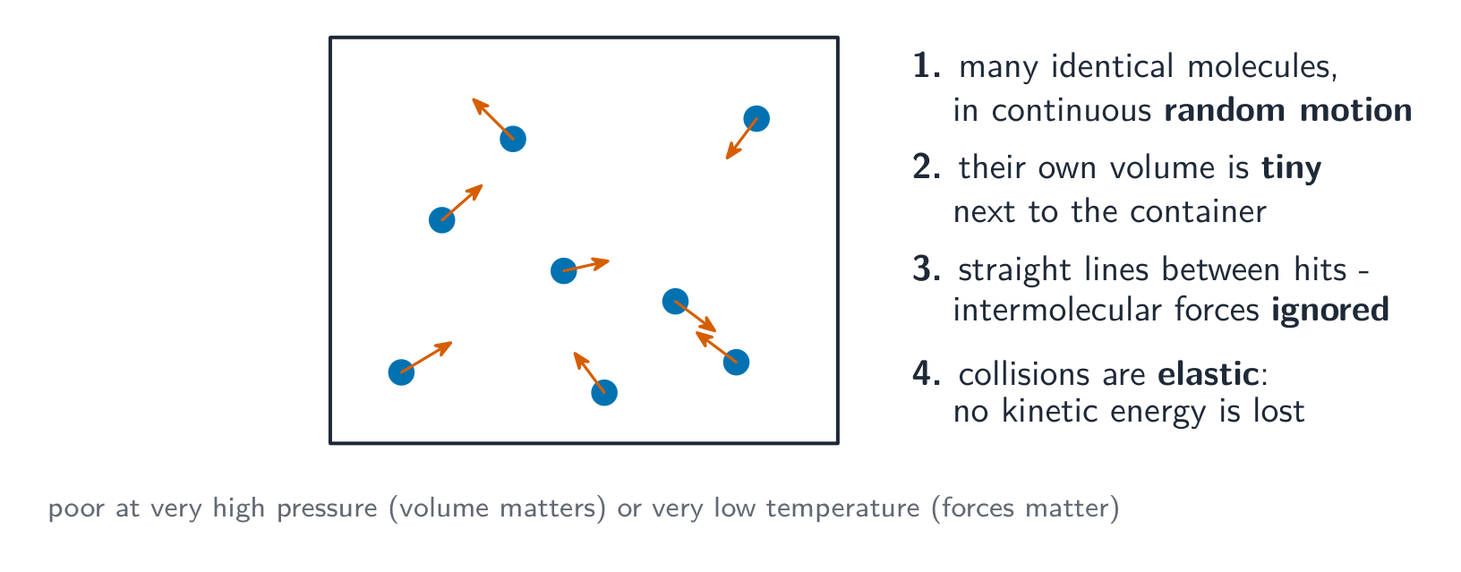
Kinetic theory: gas pressure Thermodynamics 热力学 studies heat and energy in large collections of particles. The kinetic theory 分子运动论 explains gas behavior from the random motion of its molecules:
The key assumptions of the kinetic theory of an ideal gas - Temperature 温度 is a measure of the average kinetic energy of the molecules: $K_{\text{avg}}=\tfrac{3}{2}k_B T$ (with $T$ in kelvin). Hotter means faster-moving molecules.
- Pressure 压强 comes from molecules colliding with the container walls – more frequent or harder collisions give more pressure.
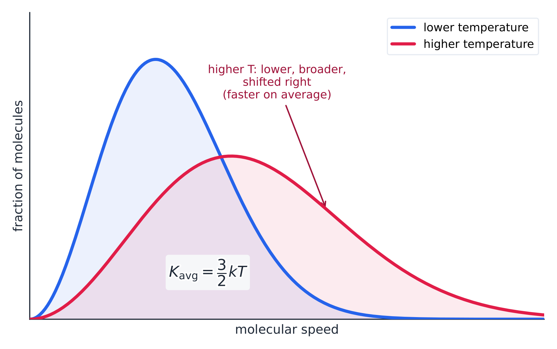
The Maxwell-Boltzmann speed distribution shifts right and flattens at higher temperature Worked example. Find the average kinetic energy of a gas molecule at $300\ \text{K}$, using $k_B=1.38\times10^{-23}\ \text{J/K}$:
$$K_{\text{avg}}=\tfrac32 k_B T=1.5\times1.38\times10^{-23}\times300=6.2\times10^{-21}\ \text{J}.$$It depends only on temperature, not on the type of gas – at the same $T$, light and heavy molecules share the same average kinetic energy (so the light ones move faster).Explore · 탐색하기Explore the spread of molecular speeds · 분자 속도 분포 탐구
Raise the temperature and watch the whole speed distribution shift right and flatten — the particles move faster on average, which is exactly what $\bar K = \tfrac{3}{2} k_B T$ means. · 온도를 높이면 전체 속도 분포가 오른쪽으로 이동하고 평평해집니다 — 입자들이 평균적으로 더 빠르게 움직이는 것은 정확히 $\bar K = \tfrac{3}{2} k_B T$가 의미하는 바입니다.
Vocabulary · 어휘 Train · 연습하기English 한국어 Thermodynamics/ˌθɜːməʊdaɪˈnæmɪks/ 열역학 kinetic theory/kɪˈnetɪk ˈθɪəri/ 운동론 Temperature/ˈtemprɪtʃə/ 온도 Pressure/ˈpreʃə/ 압력 9.2
The Ideal Gas Law
Syllabus
EnglishLearning Objective 9.2.A: Describe the properties of an ideal gas.
- 9.2.A.1 The classical model of an ideal gas assumes that the instantaneous velocities of atoms are random, the volumes of the atoms are negligible compared to the total volume occupied by the gas, the atoms collide elastically, and the only appreciable forces on the atoms are those that occur during collisions.
- 9.2.A.2 An ideal gas is one in which the relationships between pressure, volume, the number of moles or number of atoms, and temperature of a gas can be modeled using the equation
- Equation: $PV = nRT = N k_B T$
- 9.2.A.3 Graphs modeling the pressure, temperature, and volume of gases can be used to describe or determine properties of that gas.
- 9.2.A.4 A temperature at which an ideal gas has zero pressure can be extrapolated from a graph of pressure as a function of temperature.
한국어학습 목표 9.2.A: 이상 기체의 특성을 설명하라.
- 9.2.A.1 이상 기체의 고전 모델은 원자의 순간 속도가 무작위이며, 원자의 부피는 기체가 차지하는 총 부피에 비해 무시할 수 있을 정도로 작으며, 원자는 탄성 충돌을 하며, 원자에 작용하는 유의미한 힘은 충돌 시에만 발생한다고 가정한다.
- 9.2.A.2 이상 기체는 압력, 부피, 몰수 또는 원자 수, 그리고 기체의 온도의 관계를 다음 식을 사용하여 모델링할 수 있는 기체이다:
- 식: $PV = nRT = N k_B T$
- 9.2.A.3 기체의 압력, 온도, 부피를 모델링하는 그래프를 사용하여 해당 기체의 특성을 설명하거나 결정할 수 있다.
- 9.2.A.4 압력을 온도의 함수로 한 그래프로부터 이상 기체의 압력이 0이 되는 온도를 외삽할 수 있다.
Source: College Board AP Course and Exam Description · 출처: College Board AP Course and Exam Description
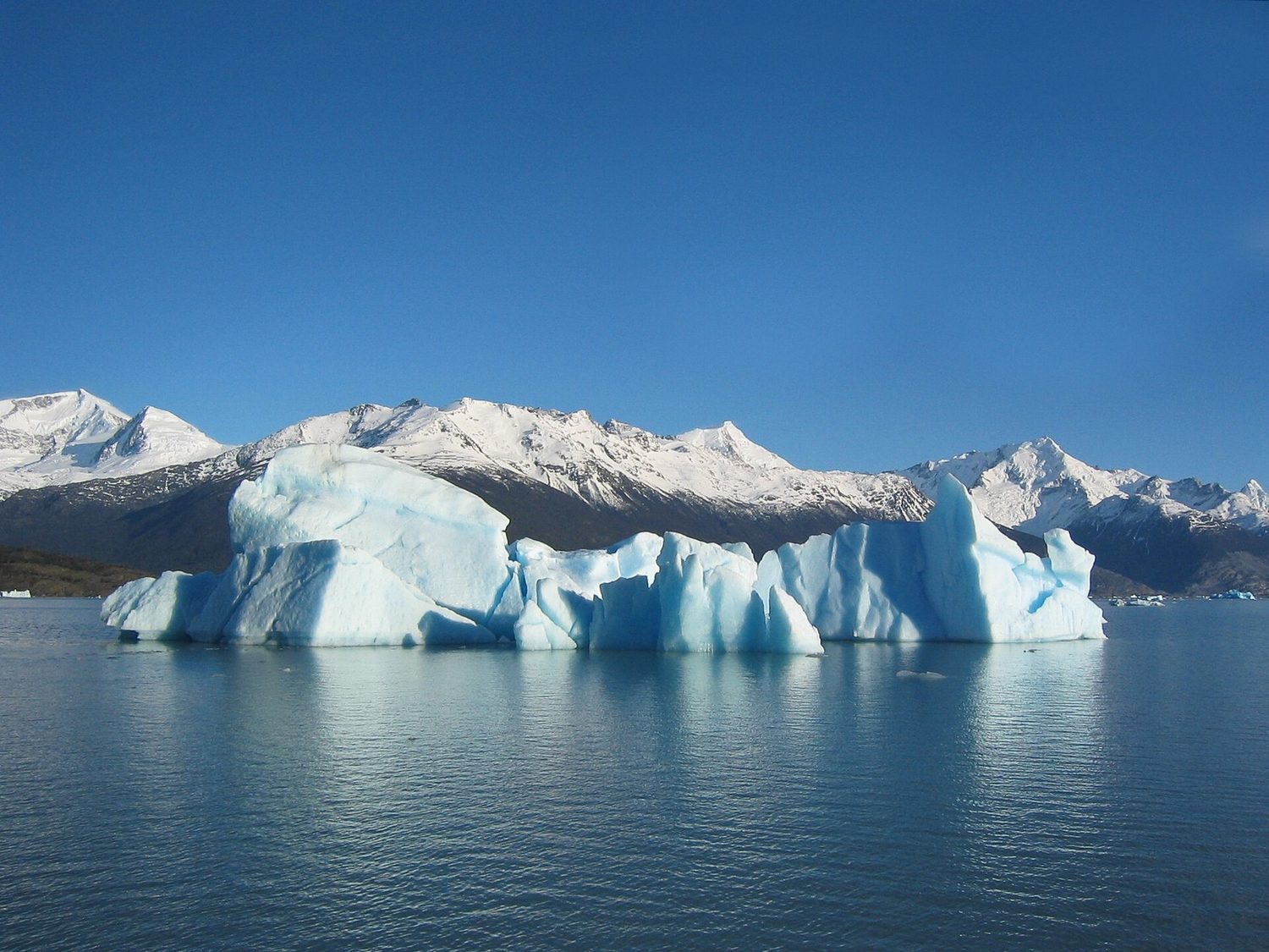
An iceberg: heat, density and phase changes connect thermodynamics to fluids and buoyancy An ideal gas 理想气体 obeys
$$PV=nRT \qquad(\text{or } PV=Nk_B T),$$linking pressure $P$, volume $V$, amount ($n$ moles or $N$ molecules), and absolute temperature $T$. Use it to predict how a gas responds when you change one quantity and hold others fixed (e.g. heating at constant volume raises pressure).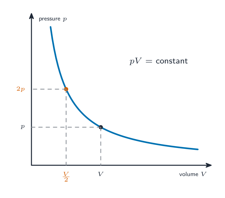
Boyle's law: at constant temperature, pressure times volume is constant Worked example. A sealed rigid container of gas is at $1.0\times10^{5}\ \text{Pa}$ and $300\ \text{K}$. It is heated to $450\ \text{K}$. Because the volume and amount are fixed, $P/T$ is constant:
$$P_2=P_1\frac{T_2}{T_1}=1.0\times10^{5}\times\frac{450}{300}=1.5\times10^{5}\ \text{Pa}.$$Always convert temperatures to kelvin before using a gas law – using Celsius here would give nonsense.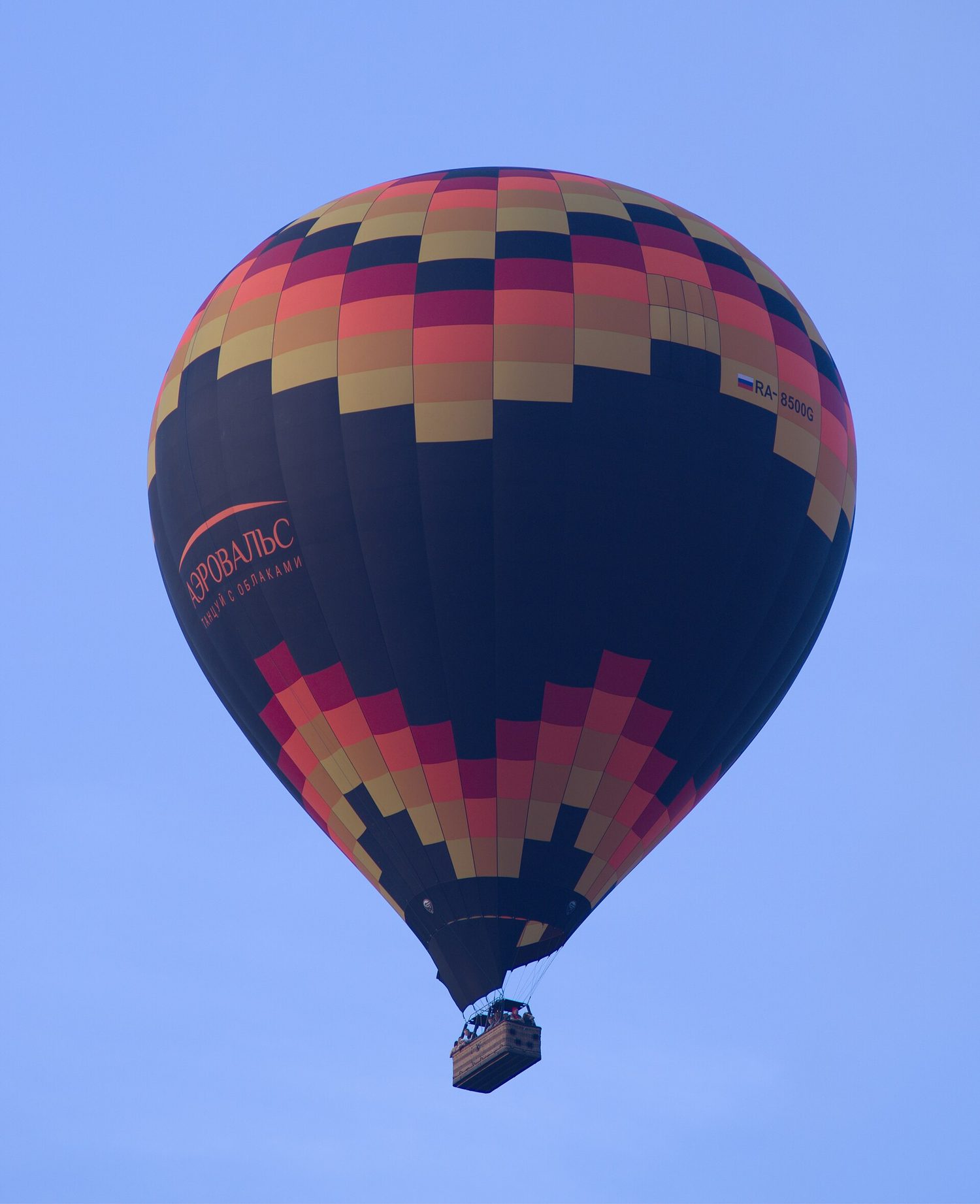
Heating the gas inside a balloon lowers its density, so the balloon rises — the ideal gas law in action Explore · 탐색하기Explore squeezing a gas · 기체 압축 탐구
Slide the piston in to shrink the volume. The same particles are crammed into less space, so they hit the walls more often and the pressure climbs — while $PV$ stays constant at fixed temperature. · 피스톤을 밀어내어 부피를 줄이세요. 같은 수의 입자가 더 좁은 공간에 갇히므로 벽에 더 자주 충돌하여 압력이 상승합니다 — 온도가 일정할 때 $PV$는 일정하게 유지됩니다.
Vocabulary · 어휘 Train · 연습하기English 한국어 ideal gas/aɪˈdɪəl ɡæs/ 이상 기체 9.3
Thermal Energy Transfer and Equilibrium
Syllabus
EnglishLearning Objective 9.3.A: Describe the transfer of energy between two systems in thermal contact due to temperature differences of those two systems.
- 9.3.A.1 Two systems are in thermal contact if the systems may transfer energy by thermal processes.
- 9.3.A.1.i Heating is the transfer of energy into a system by thermal processes.
- 9.3.A.1.ii Cooling is the transfer of energy out of a system by thermal processes.
- 9.3.A.2 The thermal processes by which energy may be transferred between systems at different temperatures are conduction, convection, and radiation.
- 9.3.A.3 Energy is transferred through thermal processes spontaneously from a higher-temperature system to a lower-temperature system.
- 9.3.A.3.i In collisions between atoms from different systems, energy is most likely to be transferred from higher-energy atoms to lower-energy atoms.
- 9.3.A.3.ii After many collisions of atoms from different systems, the most probable state is one in which both systems have the same temperature.
- 9.3.A.4 Thermal equilibrium results when no net energy is transferred by thermal processes between two systems in thermal contact with each other.
한국어학습 목표 9.3.A: 두 시스템 간 온도 차이로 인해 열접촉 상태일 때 에너지가 전달되는 과정을 설명하라.
- 9.3.A.1 두 시스템이 열접촉状态일 때,该系统们可以通过热过程传递能量。
- 9.3.A.1.i 가열(heating)은 열과정을 통해 시스템으로 에너지를 전달하는 것이다.
- 9.3.A.1.ii 냉각(cooling)은 열과정을 통해 시스템에서 에너지를 배출하는 것이다.
- 9.3.A.2 서로 다른 온도의 시스템间能量传递的thermal processes包括传导(conduction)、对流传热(convection)和辐射(radiation)。
- 9.3.A.3 에너지는 thermal processes를 통해 높은 온도 시스템에서 낮은 온도 시스템으로 자발적으로 전달된다.
- 9.3.A.3.i 서로 다른 시스템의 원자 간 충돌에서 에너지는 가장 높은 확률로 높은 에너지 원자에서 낮은 에너지 원자로 전달된다.
- 9.3.A.3.ii 서로 다른 시스템의 원자들이 여러 번 충돌한 후, 가장 가능한 상태는 양쪽 시스템이 동일한 온도를 가지는 상태이다.
- 9.3.A.4 열접촉 상태인 두 시스템间通过热过程没有净能量转移时,就达到了热平衡(thermal equilibrium)。
Source: College Board AP Course and Exam Description · 출처: College Board AP Course and Exam Description
Heat 热量 $Q$ is energy transferred because of a temperature difference; it flows from hot to cold. Two objects in contact reach thermal equilibrium 热平衡 when they share the same temperature, and net heat flow stops. The three transfer methods are conduction 传导, convection 对流, and radiation 辐射.
Explore · 탐색하기Add heat and watch the temperature · 열을 가하고 온도 변화를 관찰하세요
Adding heat usually raises temperature, but during a phase change the temperature holds flat while the energy breaks bonds. Two bodies in contact settle at one temperature — thermal equilibrium. · 열을 가하면 보통 온도가 오르지만, 상변화 중에는 에너지가 결합을 끊는 동안 온도는 일정하게 유지됩니다. 서로 접촉한 두 물체는 하나의 온도에서 열평형 상태에 도달합니다.
Vocabulary · 어휘 Train · 연습하기English 한국어 Heat/hiːt/ 열 thermal equilibrium/ˈθɜːml ˌiːkwɪˈlɪbrɪəm/ 열평형 conduction/kənˈdʌkʃn/ 전도 convection/kənˈvekʃn/ 대류 radiation/ˌreɪdɪˈeɪʃn/ 복사 9.4
The First Law of Thermodynamics
Syllabus
Learning Objective Essential Knowledge 9.4.A
Describe the internal energy of a system.- 9.4.A.1 The internal energy of a system is the sum of the kinetic energy of the objects that make up the system and the potential energy of the configuration of those objects.
- 9.4.A.1.i The atoms in an ideal gas do not interact with each other via conservative forces, and the internal structure is not considered. Therefore, an ideal gas does not have internal potential energy.
- 9.4.A.1.ii The internal energy of an ideal monatomic gas is the sum of the kinetic energies of the constituent atoms in the gas.
- Equation: $U = \dfrac{3}{2} nRT = \dfrac{3}{2} N k_B T$
- 9.4.A.2 Changes to a system's internal energy can result in changes to the internal structure and internal behavior of that system without changing the motion of the system's center of mass.
9.4.B
Describe the behavior of a system using thermodynamic processes.- 9.4.B.1 The first law of thermodynamics is a restatement of conservation of energy that accounts for energy transferred into or out of a system by work, heating, or cooling.
- 9.4.B.1.i For an isolated system, the total energy is constant.
- 9.4.B.1.ii For a closed system, the change in internal energy is the sum of energy transferred to or from the system by heating, or work done on the system.
- Equation: $\Delta U = Q + W$
- 9.4.B.1.iii The work done on a system by a constant or average external pressure that changes the volume of that system (for example, a piston compressing a gas in a container) is defined as
- Equation: $W = -P \Delta V$
- 9.4.B.2 Pressure-volume graphs (also known as PV diagrams) are representations used to represent thermodynamic processes.
- 9.4.B.2.i Lines of constant temperature on a PV diagram are called isotherms.
- 9.4.B.2.ii The absolute value of the work done on a gas when the gas expands or compresses is equal to the area underneath the curve of a plot of pressure vs. volume for the gas.
- 9.4.B.3 Special cases of thermal processes depend on the relationship between the configuration of the system, the nature of the work done on the system, and the system's surroundings. These include constant volume (isovolumetric), constant temperature (isothermal), and constant pressure (isobaric), as well as processes where no energy is transferred to or from the system through thermal processes (adiabatic).
Source: College Board AP Course and Exam Description · 출처: College Board AP Course and Exam Description
The first law 热力学第一定律 is conservation of energy for a gas:
$$\Delta U = Q + W,$$where $\Delta U$ is the change in internal energy 内能 (tied to temperature), $Q$ is heat added to the gas, and $W$ is work done on the gas. On a pressure–volume diagram, the work done by the gas is the area under the process curve. Watch signs: compressing a gas does positive work on it.A gas pushing a piston out by a small distance does work equal to p times the volume change 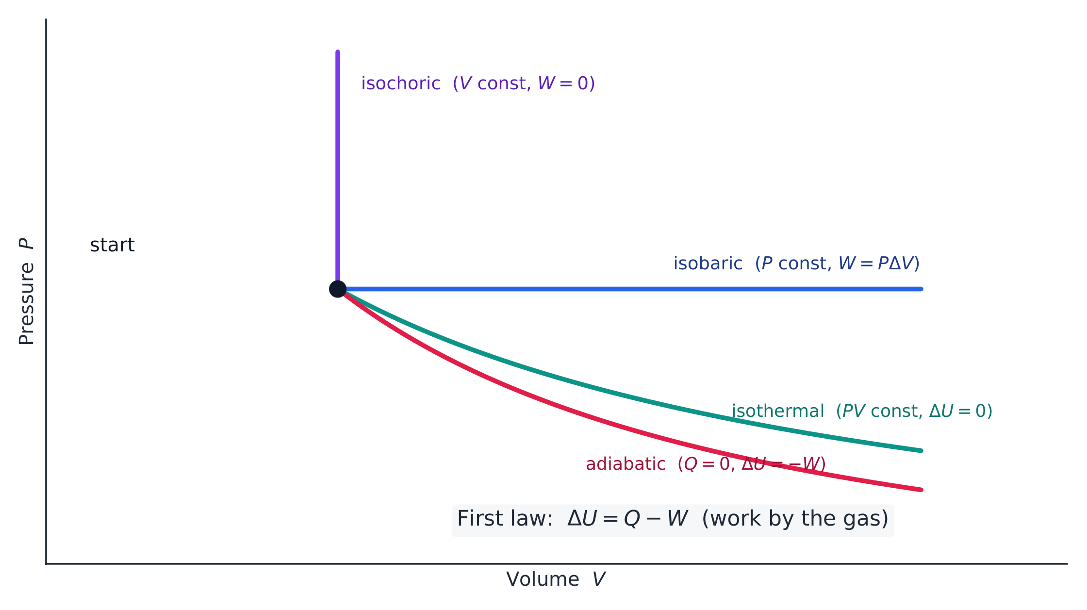
The four thermodynamic processes drawn from a common starting state on a PV diagram 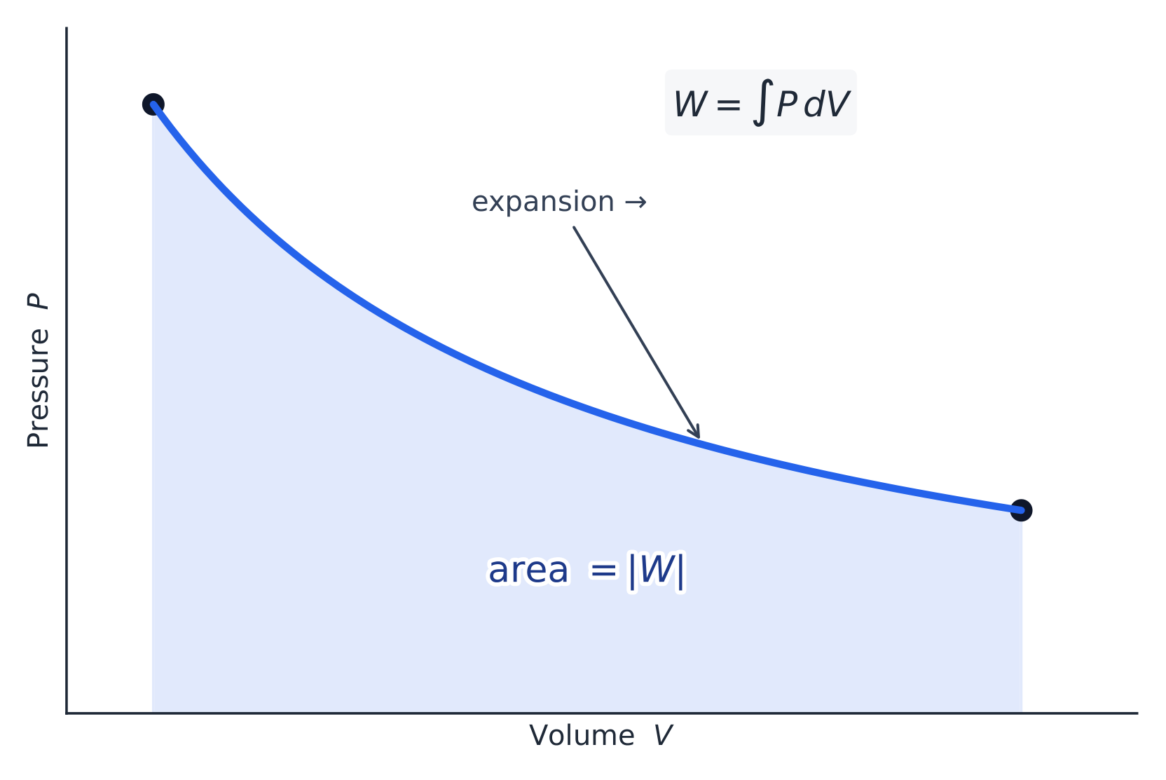
The work done during a volume change equals the area under the P-V curve Worked example. A gas absorbs $500\ \text{J}$ of heat and, as it expands, does $200\ \text{J}$ of work on its surroundings. Find the change in its internal energy. Work done on the gas is $W=-200\ \text{J}$ (it does work, so it loses that energy):
$$\Delta U=Q+W=500+(-200)=300\ \text{J}.$$The internal energy rises by $300\ \text{J}$, so the gas ends up hotter. Getting the sign of $W$ right is the whole game in first-law problems.Vocabulary · 어휘 Train · 연습하기English 한국어 first law/fɜːst lɔː/ 첫 번째 법칙 internal energy/ɪnˈtɜːnl ˈenədʒi/ 내부 에너지 9.5
Specific Heat and Thermal Conductivity
Syllabus
EnglishLearning Objective 9.5.A: Describe the energy required to change the temperature of an object by a certain amount.
- 9.5.A.1 The amount of energy required to change the temperature of a material is related to the material's specific heat.
- Equation: $Q = mc\Delta T$
- 9.5.A.2 The specific heat of a material is an intrinsic property of that material that depends on the arrangement and interactions of the atoms that make up the material.
Learning Objective 9.5.B: Describe the rate at which energy is transferred by conduction through a given material.
- 9.5.B.1 The rate at which energy is transferred by conduction through a given material is related to the thermal conductivity, the physical dimensions of the material, and the temperature difference across the material.
- Equation: $\dfrac{Q}{\Delta t} = \dfrac{kA\Delta T}{L}$
- 9.5.B.2 The thermal conductivity of a material is an intrinsic property of that material that depends on the arrangement and interactions of the atoms that make up the material.
Boundary statement: AP Physics 2 will model specific heat as independent of temperature.
한국어학습 목표 9.5.A: 특정 양만큼物体的 온도를 변화시키는 데 필요한 에너지를 설명하시오.
- 9.5.A.1 물질의 온도를 변화시키는 데 필요한 에너지의 양은 해당 물질의 비열과 관련이 있다.
- 식: $Q = mc\Delta T$
- 9.5.A.2 물질의 비열은 해당 물질을 구성하는 원자의 배열 및 상호작용에 의존하는 물질 고유의 성질이다.
학습 목표 9.5.B: 주어진 물질을 통한 전도에 의해 에너지가 전달되는 속도를 설명하시오.
- 9.5.B.1 주어진 물질을 통한 전도에 의해 에너지가 전달되는 속도는 열전도도, 물질의 물리적 크기, 그리고 물질을 가로지르는 온도차와 관련이 있다.
- 식: $\dfrac{Q}{\Delta t} = \dfrac{kA\Delta T}{L}$
- 9.5.B.2 물질의 열전도도는 해당 물질을 구성하는 원자의 배열 및 상호작용에 의존하는 물질 고유의 성질이다.
범위 명시: AP Physics 2에서는 비열이 온도에 독립적으로 모델링되도록 한다.
Source: College Board AP Course and Exam Description · 출처: College Board AP Course and Exam Description
- Specific heat 比热容 $c$ is the heat needed to raise one kilogram by one degree: $Q=mc\,\Delta T$. A high specific heat (like water's) means a substance resists temperature change.
- Thermal conductivity 热导率 measures how fast heat conducts through a material; the rate of conduction rises with area and temperature difference and falls with thickness.
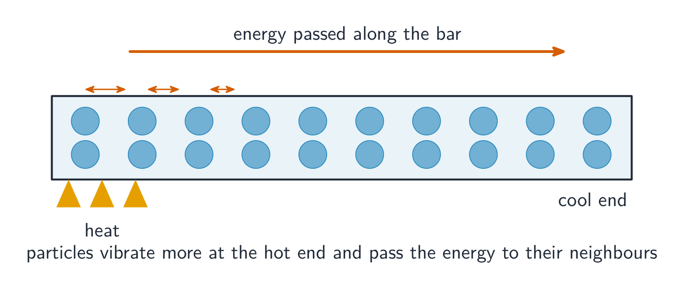
Conduction: vibrating particles pass energy along a metal bar Worked example. How much heat raises the temperature of $2.0\ \text{kg}$ of water from $20\,{}^{\circ}\text{C}$ to $80\,{}^{\circ}\text{C}$? Water's specific heat is $c=4200\ \text{J/(kg}\,{}^{\circ}\text{C)}$:
$$Q=mc\,\Delta T=2.0\times4200\times(80-20)=5.0\times10^{5}\ \text{J}.$$Water's large specific heat is why it is used as a coolant and why coastal climates are mild.Explore · 탐색하기Explore how much energy heats a material · 재료를 가열하는 데 필요한 에너지 양 탐구
Pick a material, set the mass and temperature rise, and read the energy from $Q = mc\,\Delta T$. Water needs far more energy than the metals to warm by the same amount. · 재료를 선택하고 질량 및 온도 상승치를 설정하면, $Q = mc\,\Delta T$에서 에너지를 읽을 수 있습니다. 물은 동일한 온도 상승을 위해 금속보다 훨씬 많은 에너지가 필요합니다.
Vocabulary · 어휘 Train · 연습하기English 한국어 Specific heat/spəˈsɪfɪk hiːt/ 비열 Thermal conductivity/ˈθɜːml kɒndəkˈtɪvɪti/ 열전도도 9.6
Entropy and the Second Law of Thermodynamics
Syllabus
Learning Objective Essential Knowledge 9.6.A
Describe the change in entropy for a given system over time.- 9.6.A.1 The second law of thermodynamics states that the total entropy of an isolated system can never decrease and is constant only when all processes the system undergoes are reversible.
- 9.6.A.2 Entropy can be qualitatively described as the tendency of energy to spread or the unavailability of some of the system's energy to do work.
- 9.6.A.2.i Localized energy will tend to disperse and spread out.
- 9.6.A.2.ii Entropy is a state function and therefore only depends on the current state or configuration of a system, not how the system reached that state.
- 9.6.A.2.iii Maximum entropy occurs when a system is in thermodynamic equilibrium.
- 9.6.A.3 The change in a system's entropy is determined by the system's interactions with its surroundings.
- 9.6.A.3.i Isolated systems spontaneously move toward thermodynamic equilibrium.
- 9.6.A.3.ii The entropy of an isolated system never decreases, but the entropy of a closed system can decrease because energy can be transferred into or out of the system.
Boundary statement: Only qualitative treatment of the second law of thermodynamics is within the scope of AP Physics 2.
Source: College Board AP Course and Exam Description · 출처: College Board AP Course and Exam Description
Entropy 熵 measures the disorder, or the number of ways to arrange, a system. The second law 热力学第二定律: the total entropy of an isolated system never decreases – energy naturally spreads out. This sets the direction of processes: heat flows hot→cold on its own, never the reverse, and no engine can convert heat entirely into work.
Vocabulary · 어휘 Train · 연습하기English 한국어 Entropy/ˈentrəpi/ 엔트로피 second law/ˈsekənd lɔː/ 두 번째 법칙 9.6
Exam tips
- Always convert temperatures to kelvin ($T_{\text{K}}=T_{\text{C}}+273$) before using any gas law.
- In the first law $\Delta U = Q + W$, get the sign of $W$ right: work done on the gas is positive; when the gas expands and does work on its surroundings, $W$ is negative.
- Temperature measures the average kinetic energy of particles, so at the same $T$ lighter molecules move faster.
- On a PV diagram the work done by the gas is the area under the process curve.
- Use $Q=mc\,\Delta T$ for temperature change; the second law fixes the direction — heat flows hot→cold and total entropy never decreases.
-
10
Electric Force, Field, and Potential
Watch lesson · 수업 보기10.1
Electric Charge and Electric Force
Syllabus
EnglishLearning Objective 10.1.A: Describe the electric force that results from the interactions between charged objects or systems.
- 10.1.A.1 Charge is a fundamental property of all matter.
- 10.1.A.1.i Charge is described as positive or negative.
- 10.1.A.1.ii The magnitude of the charge of a single electron or proton, the elementary charge $e$, can be considered to be the smallest indivisible amount of charge.
- 10.1.A.1.iii The charge of an electron is $-e$, the charge of a proton is $+e$, and a neutron has no electric charge.
- 10.1.A.1.iv A point charge is a model in which the physical size of a charged object or system is negligible in the context of the situation being analyzed.
- 10.1.A.2 Coulomb's law describes the electrostatic force between two charged objects as directly proportional to the magnitude of each of the charges and inversely proportional to the square of the distance between the objects.
- Equation: $\left|\vec{F}_E\right| = \dfrac{1}{4\pi\varepsilon_0}\dfrac{\left|q_1 q_2\right|}{r^2} = k\dfrac{\left|q_1 q_2\right|}{r^2}$
- 10.1.A.3 The direction of the electrostatic force depends on the signs of the charges of the interacting objects and is parallel to the line of separation between the objects.
- 10.1.A.3.i Two objects with charges of the same sign exert repulsive forces on each other.
- 10.1.A.3.ii Two objects with charges of opposite signs exert attractive forces on each other.
- 10.1.A.4 Electric forces are responsible for some of the macroscopic properties of objects in everyday experiences. However, the large number of particle interactions that occur make it more convenient to treat everyday forces in terms of nonfundamental forces called contact forces, such as normal force, friction, and tension.
Learning Objective 10.1.B: Describe the electric and gravitational forces that result from interactions between charged objects with mass.
- 10.1.B.1 Electrostatic forces can be attractive or repulsive, while gravitational forces are always attractive.
- 10.1.B.2 For any two objects that have mass and electric charge, the magnitude of the gravitational force is usually much smaller than the magnitude of the electrostatic force.
- 10.1.B.3 Gravitational forces dominate at larger scales even though they are weaker than electrostatic forces, because systems at large scales tend to be electrically neutral.
Learning Objective 10.1.C: Describe the electric permittivity of a material or medium.
- 10.1.C.1 Electric permittivity is a measurement of the degree to which a material or medium is polarized in the presence of an electric field.
- 10.1.C.2 Electric polarization can be modeled as the induced rearrangement of electrons by an external electric field, resulting in a separation of positive and negative charges within a material or medium.
- 10.1.C.3 Free space has a constant value of electric permittivity, $\varepsilon_0$, that appears in physical relationships.
- 10.1.C.4 The permittivity of matter has a value different from that of free space that arises from the matter's composition and arrangement.
- 10.1.C.4.i In a given material, electric permittivity is determined by the ease with which electrons can change configurations within the material.
- 10.1.C.4.ii Conductors are made from electrically conducting materials in which charge carriers move easily; insulators are made from electrically nonconducting materials in which charge carriers cannot move easily.
Boundary statement: AP Physics 2 only expects students to make calculations of the electric force between four or fewer interacting charged objects or systems. The analysis of the resulting electric force from more charges is allowed in situations of high symmetry.
한국어학습 목표 10.1.A: 전하를 띤 물체 또는 시스템 간의 상호작용으로 인해 발생하는 전기력을 설명하라.
- 10.1.A.1 전하는 모든 물질의 기본 성질이다.
- 10.1.A.1.i 전하는 양전하 또는 음전하로 기술된다.
- 10.1.A.1.ii 단일 전자 또는 양성자의 전하 크기인 기본 전하 $e$는 가장 작고 나눌 수 없는 전하의 양으로 간주할 수 있다.
- 10.1.A.1.iii 전자의 전하량은 $-e$이며, 양성자의 전하량은 $+e$이고, 중성자는 전기적 전하를 가지지 않는다.
- 10.1.A.1.iv 점전하는 분석되고 있는 상황 맥락에서 전하를 띤 물체나 시스템의 물리적 크기가 무시할 수 있을 정도로 작은 모델이다.
- 10.1.A.2 쿨롱의 법칙은 두 전하를 띤 물체 사이의 정전기력이 각 전하의 크기에 비례하고 물체 사이의 거리의 제곱에 반비례함을 기술한다.
- 식: $\left|\vec{F}_E\right| = \dfrac{1}{4\pi\varepsilon_0}\dfrac{\left|q_1 q_2\right|}{r^2} = k\dfrac{\left|q_1 q_2\right|}{r^2}$
- 10.1.A.3 정전기력의 방향은 상호작용하는 물체의 전하 부호에 따라 결정되며, 물체 사이의 분리선과 평행하다.
- 10.1.A.3.i 같은 부호의 전하를 가진 두 물체는 서로 밀착력을 가한다.
- 10.1.A.3.ii 반대 부호의 전하를 가진 두 물체는 서로 인력을 가한다.
- 10.1.A.4 전기력은 일상 경험에서 보는 물체의 일부 거시적 성질에 책임이 있다. 그러나 수많은 입자 상호작용이 일어나므로, 일상적인 힘들을的法線力, 마찰력, 장력과 같은 비기본적인 힘인 접촉력으로 취급하는 것이 더 편리하다.
학습 목표 10.1.B: 질량을 가진 전하를 띤 물체 간의 상호작용으로 인해 발생하는 전기력과 중력 để 설명하라.
- 10.1.B.1 정전기력은 인력이나 반발력이 될 수 있지만, 중력은 항상 인력이다.
- 10.1.B.2 질량과 전기하전을 가진 두 물체 사이의 중력 힘의 크기는 일반적으로 정전기 힘의 크기보다 훨씬 작다.
- 10.1.B.3 중력 힘은 정전기 힘보다 약하지만, 거시적 규모에서는 전하가 중성인 시스템이 대부분이기 때문에 중력 힘이 지배적이다.
학습 목표 10.1.C: 물질이나 매질의 전기유전율에 대해 설명하시오.
- 10.1.C.1 전기유전율은 외부 전기장 존재 시 물질이나 매질이 극화되는 정도를 나타내는 측정값이다.
- 10.1.C.2 전기 극화는 외부 전기장에 의해 전자 배치가 유도되어 재배열되는 것으로 모델링할 수 있으며, 이는 물질 내부에서 양전하와 음전하의 분리를 초래한다.
- 10.1.C.3 진공은 물리적 관계식에 등장하는 일정한 값 $\varepsilon_0$을 갖는 전기유전율을 가진다.
- 10.1.C.4 물질의 유전율은 진공의 유전율과 다르며, 이는 물질의 구성 및 배열에 기인한다.
- 10.1.C.4.i 주어진 물질에서 전기유전율은 전자들이 물질 내에서 configuration(배치)을 변경하는 용이성에 의해 결정된다.
- 10.1.C.4.ii 도체는 전하 운반자가 쉽게 이동할 수 있는 전기적으로 전도성 있는 소재로 만들어졌으며, 절연체는 전하 운반자가 쉽게 이동할 수 없는 전기적으로 비전도성 있는 소재로 만들어졌다.
경계 문구: AP Physics 2는 학생들에게 네 개 이하의 상호작용하는 하전된 물체 또는 시스템 간의 전기힘 계산을 요구할 뿐이다. 더 많은 전하로부터 발생하는 전기힘 분석은 높은 대칭성을 가지는 상황에서 허용된다.
Source: College Board AP Course and Exam Description · 출처: College Board AP Course and Exam Description
Electric charge 电荷 is a fundamental property of matter, and it comes in two kinds, positive and negative; like charges repel and opposite charges attract. Charge is conserved and quantized (a multiple of the elementary charge $e$). The force between two point charges is Coulomb's law 库仑定律:
$$F=\frac{k q_1 q_2}{r^2},$$directed along the line joining them – an inverse-square law like gravity, but it can push or pull.The constant $k$ hides a property of the medium: the permittivity 介电常数. Free space has a fixed permittivity of free space $\varepsilon_0$ (with $k = 1/4\pi\varepsilon_0$), while the permittivity of matter differs from $\varepsilon_0$, depending on the material's composition and arrangement - which is why a material between two charges changes the force. Note also that although the electric force is vastly stronger than gravity, gravity dominates at large scales, because large objects are usually electrically neutral (equal + and −), leaving only gravity to act.
Worked example. Two point charges, $+3.0\ \mu\text{C}$ and $-2.0\ \mu\text{C}$, sit $0.10\ \text{m}$ apart ($k=9.0\times10^{9}$). The force between them is
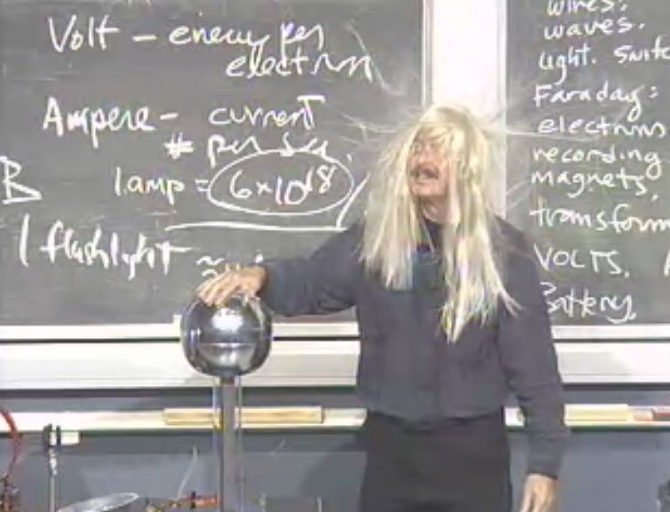
$$F=\frac{k q_1 q_2}{r^2}=\frac{9.0\times10^{9}\times(3.0\times10^{-6})(2.0\times10^{-6})}{(0.10)^2}=5.4\ \text{N},$$attractive, because the charges have opposite signs. (Use the magnitudes for the size and decide the direction from the signs.)Like charges repel: each hair carries the same charge from the Van de Graaff generator, so they push apart Vocabulary · 어휘 Train · 연습하기English 한국어 Electric charge/ɪˈlektrɪk tʃɑːdʒ/ 전기하전 Coulomb's law/ˈkuːlɒmz lɔː/ 쿨롱의 법칙 permittivity/ˌpɜːmɪˈtɪvəti/ 유전율 10.2
The Process of Charging
Syllabus
EnglishLearning Objective 10.2.A: Describe the behavior of a system using conservation of charge.
- 10.2.A.1 The net charge or charge distribution of a system can change in response to the presence of, or changes in, the net charge or charge distribution of other systems.
- 10.2.A.1.i The net charge of a system can change due to friction or contact between systems.
- 10.2.A.1.ii Induced charge separation occurs when the electrostatic force between two systems alters the distribution of charges within the systems, resulting in the polarization of one or both systems.
- 10.2.A.1.iii Induced charge separation can occur in neutral systems.
- 10.2.A.2 Any change to a system's net charge is due to a transfer of charge between the system and its surroundings.
- 10.2.A.2.i The charging of a system typically involves the transfer of electrons to and from the system.
- 10.2.A.2.ii The net charge of a system will be constant unless there is a transfer of charge to or from the system.
- 10.2.A.3 Grounding involves electrically connecting a charged system to a much larger and approximately neutral system (e.g., Earth).
한국어학습 목표 10.2.A: 하전 보존 법칙을 사용하여 시스템의 거동을 설명하시오.
- 10.2.A.1 시스템의 총하전 또는 하전 분포는 다른 시스템의 총하전 또는 하전 분포의 존재나 변화에 따라 바뀔 수 있다.
- 10.2.A.1.i 시스템의 총하전은 마찰이나 접촉에 의해 변할 수 있다.
- 10.2.A.1.ii 유도하전분리는 두 시스템 간의 정전기력이 시스템 내 하전 분포를 변화시켜 하나 이상의 시스템을 극화시키는 현상이다.
- 10.2.A.1.iii 유도하전분리는 중성 시스템에서도 발생할 수 있다.
- 10.2.A.2 시스템의 총하전 변화는 항상 시스템과 주변 환경 간에 하전이 전달됨에 의해 발생한다.
- 10.2.A.2.i 시스템의 충전은 일반적으로 전자들이 시스템으로 들어오거나 나가는 전달 과정을 포함한다.
- 10.2.A.2.ii 시스템으로의 하전 전달이 없으면 시스템의 총하전은 일정하게 유지된다.
- 10.2.A.3 접지(earthing)는 하전된 시스템을 지구의 예처럼 훨씬 크고 거의 중성인 시스템과 전기적으로 연결하는 것을 의미한다.
Source: College Board AP Course and Exam Description · 출처: College Board AP Course and Exam Description
Objects charge by moving electrons. A conductor 导体 lets charge move freely; an insulator 绝缘体 holds it in place. Three methods:
- Friction: rubbing transfers electrons.
- Conduction 接触起电: touching shares charge.
- Induction 感应起电: a nearby charge rearranges charge in a neutral object, which can then be grounded to leave it charged.
Explore · 탐색하기Charge an object by rubbing · 마찰로 물체에 전하를 띠게 하기
Rubbing transfers electrons from one surface to another, leaving one positively and one negatively charged. Like charges repel, opposite charges attract. · 마찰은 한 표면에서 다른 표면으로 전자를 이동시켜,其中一个表面이 양전하를, 다른 surface이 음전하를 띠게 합니다. 같은 전하는 서로 밀고, 다른 전하는 서로 끌어당깁니다.
Vocabulary · 어휘 Train · 연습하기English 한국어 conductor/kənˈdʌktə/ 도체 insulator/ˈɪnsjuːleɪtə/ 절연체 Conduction/kənˈdʌkʃn/ 전도 Induction/ɪnˈdʌkʃn/ 신입 사원 교육(인덕션) 10.3
Electric Fields
Syllabus
Learning Objective Essential Knowledge 10.3.A
Describe the electric field produced by a charged object or configuration of point charges.- 10.3.A.1 Electric fields may originate from charged objects.
- 10.3.A.2 The electric field at a given point is the ratio of the electric force exerted on a test charge at that point to the charge of the test charge.
- Equation: $\vec{E} = \dfrac{\vec{F}_E}{q}$
- 10.3.A.2.i A test charge is a point charge of small enough magnitude such that its presence does not significantly affect an electric field in its vicinity.
- 10.3.A.2.ii An electric field points away from isolated positive charges and toward isolated negative charges.
- 10.3.A.2.iii The electric force exerted on a positive test charge by an electric field is in the same direction as the electric field.
- 10.3.A.3 The electric field is a vector quantity and can be represented in space using vector field maps.
- 10.3.A.3.i The net electric field at a given location is the vector sum of individual electric fields created by nearby charged objects.
- 10.3.A.3.ii Electric field maps use vectors to depict the magnitude and direction of the electric field at many locations within a given region.
- 10.3.A.3.iii Electric field line diagrams are simplified models of electric field maps and can be used to determine the relative magnitude and direction of the electric field at any position in the diagram.
10.3.B
Describe the electric field generated by charged conductors or insulators.- 10.3.B.1 While in electrostatic equilibrium, the excess charge of a solid conductor is distributed on the surface of the conductor, and the electric field within the conductor is zero.
- 10.3.B.1.i At the surface of a charged conductor, the electric field is perpendicular to the surface.
- 10.3.B.1.ii The electric field outside an isolated sphere with spherically symmetric charge distribution is the same as the electric field due to a point charge with the same net charge as the sphere located at the center of the sphere.
- 10.3.B.2 While in electrostatic equilibrium, the excess charge of an insulator is distributed throughout the interior of the insulator as well as at the surface, and the electric field within the insulator may have a nonzero value.
Boundary statement: AP Physics 2 only expects students to make calculations of the electric field resulting from four or fewer charged objects or systems. Analysis of the electric field resulting from more charges is allowed in situations of high symmetry. Students will only be expected to perform qualitative analysis of electric fields within insulators.
Source: College Board AP Course and Exam Description · 출처: College Board AP Course and Exam Description
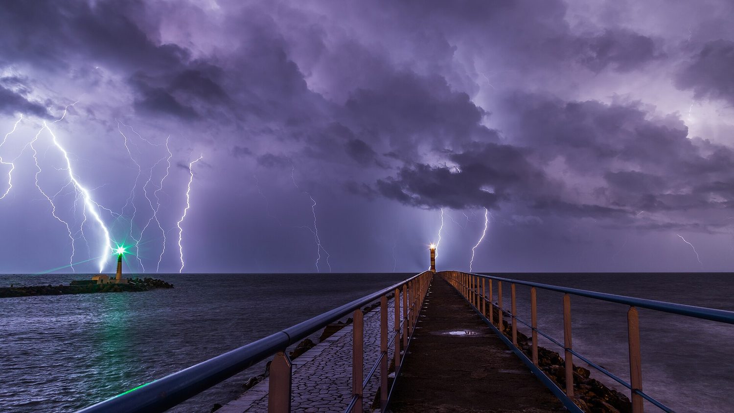
The electric field of a dipole Lightning: charge builds up until the electric field between cloud and ground is strong enough to tear electrons off air molecules, and a huge current flows An electric field 电场 $\vec{E}$ is the force per unit charge that a small positive test charge would feel:
$$\vec{E}=\frac{\vec{F}}{q},\qquad E=\frac{kQ}{r^2}\ \text{for a point charge}.$$Field lines point away from positive charges and toward negative ones; where they are denser, the field is stronger. A charge in a field feels $\vec{F}=q\vec{E}$.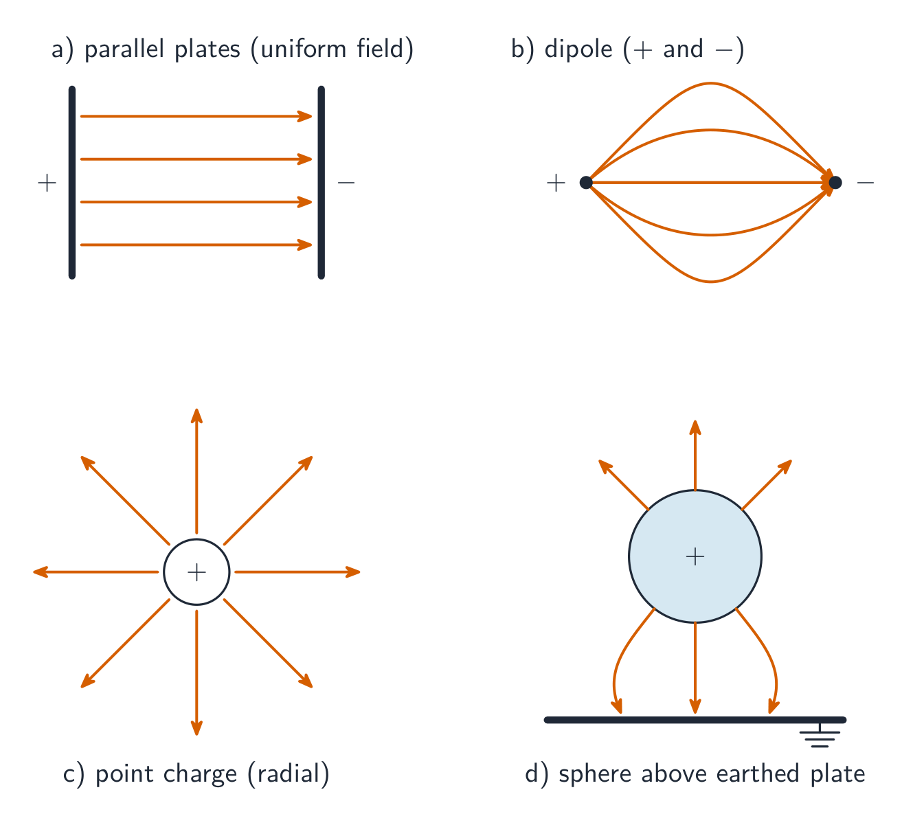
Electric field-line patterns for parallel plates, a dipole, and a point charge Worked example. Find the electric field $0.20\ \text{m}$ from a $+5.0\ \mu\text{C}$ point charge: $E=\dfrac{kQ}{r^2}=\dfrac{9.0\times10^{9}\times5.0\times10^{-6}}{(0.20)^2}=1.1\times10^{6}\ \text{N/C}$, pointing away from the charge. A $+2\ \text{nC}$ charge placed there would feel $F=qE=2\times10^{-9}\times1.1\times10^{6}=2.2\times10^{-3}\ \text{N}$.
Explore · 탐색하기Map the field around a charge · 전하 주변의 장을 그리기
An electric field points the way a positive test charge would be pushed: away from a positive charge, toward a negative one. Closer lines mean a stronger field. · 전기장은 양의 시험 전하가 밀려나는 방향을 나타냅니다: 양전하에서는 멀어지고, 음전하에서는 가까워지는 방향입니다. 선이 밀집할수록 장이 강합니다.
Vocabulary · 어휘 Train · 연습하기English 한국어 electric field/ɪˈlektrɪk fiːld/ 전기장 10.4
Electric Potential Energy
Syllabus
EnglishLearning Objective 10.4.A: Describe the electric potential energy of a system.
- 10.4.A.1 The electric potential energy of a system of two point charges equals the amount of work required for an external force to bring the point charges to their current positions from infinitely far away.
- 10.4.A.2 The general form for the electric potential energy of two charged objects is given by the equation
- Equation: $U_E = \dfrac{1}{4\pi\varepsilon_0}\dfrac{q_1 q_2}{r} = k\dfrac{q_1 q_2}{r}$
- 10.4.A.3 The total electric potential energy of a system can be determined by finding the sum of the electric potential energies of the individual interactions between each pair of charged objects in the system.
Boundary statement: As the methods to calculate the electric potential energy due to extended charge distributions exceed the scope of the course, AP Physics 2 only requires that students calculate the electric potential energy of configurations of four or fewer point charges.
한국어학습 목표 10.4.A: 시스템의 전기적ポテン셜 에너지를 설명하시오.
- 10.4.A.1 두 점전하 시스템의 전기적ポテン셜 에너지는 외부력이 점전하들을 무한히 먼 곳에서 현재 위치까지 가져오는 데 필요한 일의 양과 같다.
- 10.4.A.2 두 전하를 띤 물체의 전기적ポテン셜 에너지에 대한 일반형은 다음 식으로 주어진다.
- 식: $U_E = \dfrac{1}{4\pi\varepsilon_0}\dfrac{q_1 q_2}{r} = k\dfrac{q_1 q_2}{r}$
- 10.4.A.3 시스템의 총 전기적ポ텐셜 에너지는 시스템 내 각 쌍의 전하물체 간의 개별 상호작용에 대한 전기적ポ텐셜 에너지들의 합을 구함으로써 결정할 수 있다.
경계 문구: 확장된 전하 분포로 인한 전기적ポ텐셜 에너지를 계산하는 방법은 과정 범위를 초과하므로, AP 물리학 2에서는 학생이 네 개 이하의 점전하 구성에 대한 전기적ポ텐셜 에너지만 계산하도록 요구한다.
Source: College Board AP Course and Exam Description · 출처: College Board AP Course and Exam Description
Two charges have electric potential energy 电势能 stored in their arrangement:
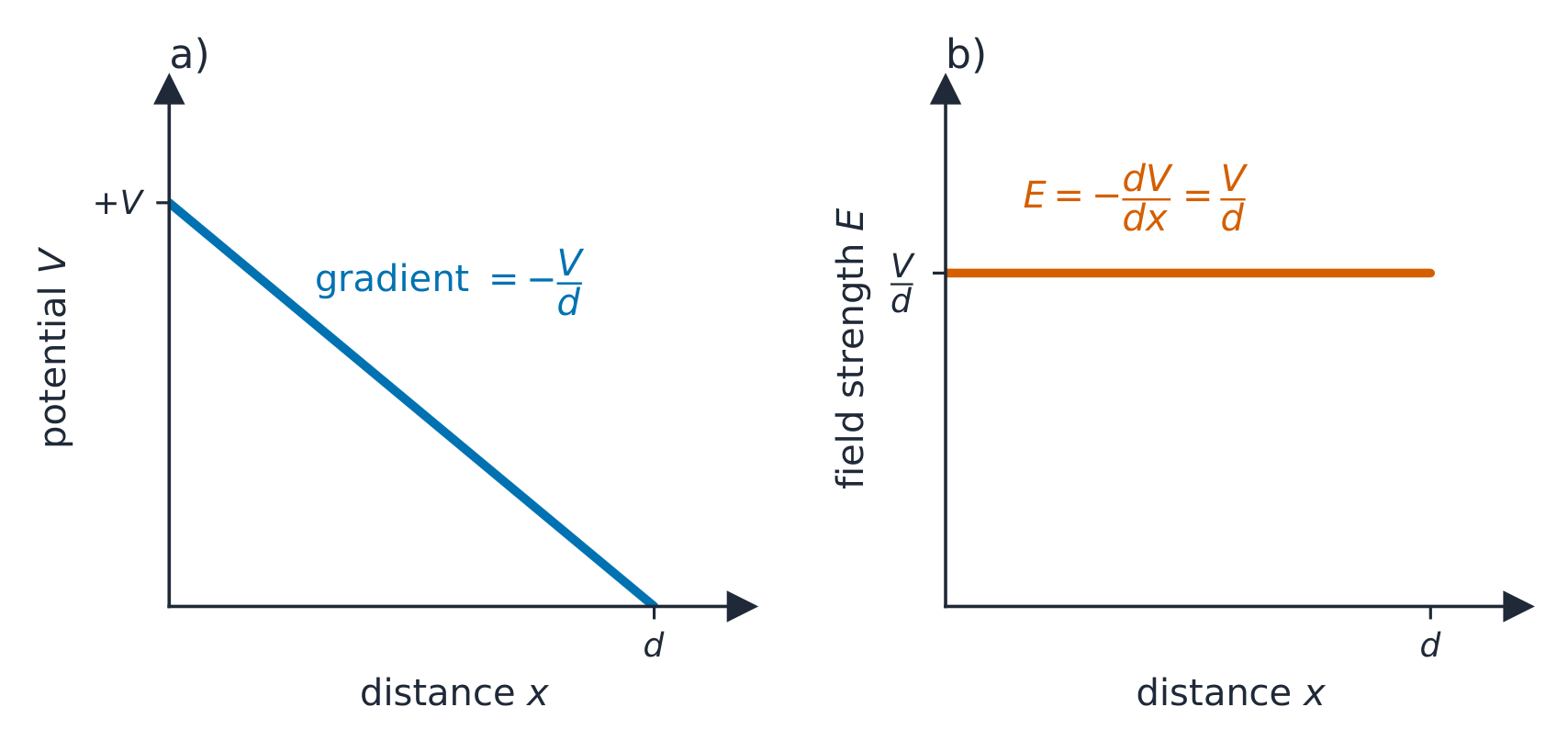
$$U=\frac{k q_1 q_2}{r}.$$Like charges pushed together store positive energy; opposite charges have negative energy (bound). Moving a charge changes $U$, and the electric force does work equal to $-\Delta U$.In a uniform field the potential falls steadily with distance, so E relates to V Vocabulary · 어휘 Train · 연습하기English 한국어 electric potential energy/ɪˈlektrɪk pəˈtenʃl ˈenədʒi/ 전기 전위 에너지 10.5
Electric Potential
Syllabus
EnglishLearning Objective 10.5.A: Describe the electric potential due to a configuration of charged objects.
- 10.5.A.1 Electric potential describes the electric potential energy per unit charge at a point in space.
- 10.5.A.2 The electric potential due to multiple point charges can be determined by the principle of scalar superposition of the electric potential due to each of the point charges.
- Equation: $V = \dfrac{1}{4\pi\varepsilon_0}\sum_{i}\dfrac{q_i}{r_i}$
- 10.5.A.3 The electric potential difference between two points is the change in electric potential energy per unit charge when a test charge is moved between the two points.
- Equation: $\Delta V = \dfrac{\Delta U_E}{q}$
- 10.5.A.3.i Electric potential difference may also result from chemical processes that cause positive and negative charges to separate, such as in a battery.
- 10.5.A.4 When conductors are in electrical contact, electrons will be redistributed such that the surfaces of the conductors are at the same electric potential.
Learning Objective 10.5.B: Describe the relationship between electric potential and electric field.
- 10.5.B.1 The average electric field between two points in space is equal to the electric potential difference between the two points divided by the distance between the two points.
- Equation: $\left|\vec{E}\right| = \left|\dfrac{\Delta V}{\Delta r}\right|$
- 10.5.B.2 Electric field vector maps and equipotential lines are tools to describe the field produced by a charge or configuration of charges and can be used to predict the motion of charged objects in the field.
- 10.5.B.2.i Equipotential lines represent lines of equal electric potential in space. These lines are also referred to as isolines of electric potential.
- 10.5.B.2.ii Isolines are perpendicular to electric field vectors. An isoline map of electric potential can be constructed from an electric field vector map, and an electric field map may be constructed from an isoline map.
- 10.5.B.2.iii An electric field vector points in the direction of decreasing potential.
- 10.5.B.2.iv There is no component of an electric field along an isoline.
Boundary statement: As the methods to calculate the electric potential due to extended charges exceed the scope of the course, AP Physics 2 only expects that students calculate the electric potential of configurations of four or fewer particles (or more in situations of high symmetry).
한국어학습 목표 10.5.A: 전하물체 구성에 의한 전기적ポ텐셜을 설명하시오.
- 10.5.A.1 전기적ポ텐셜은 공간 상의 한 점에서 단위 전하당 전기적ポ텐셜 에너지를 나타낸다.
- 10.5.A.2 여러 점전하에 의한 전기적ポ텐셜은 각 점전하에 의한 전기적ポ텐셜의 스칼라 중첩 원리에 의해 결정될 수 있다.
- 식: $V = \dfrac{1}{4\pi\varepsilon_0}\sum_{i}\dfrac{q_i}{r_i}$
- 10.5.A.3 두 지점 사이의 전기적ポ텐셜 차이는 시험전하가 두 지점 사이를 이동할 때 단위 전하당 전기적ポ텐셜 에너지의 변화량이다.
- 식: $\Delta V = \dfrac{\Delta U_E}{q}$
- 10.5.A.3.i 전기적ポ텐셜 차이는 양전하와 음전하를 분리시키는 화학적 과정(예: 배터리)에서도 발생할 수 있다.
- 10.5.A.4 도체가 전기적으로 접촉되어 있을 때, 전자들은 재배분되어 도체 표면들이 동일한 전기적ポ텐셜이 되도록 된다.
학습 목표 10.5.B: 전기적ポ텐셜과 전기장의 관계를 설명하시오.
- 10.5.B.1 공간 상의 두 지점 사이의 평균 전기장은 두 지점 사이의 전기적ポ텐셜 차이를 두 지점 간 거리로 나눈 값과 같다.
- 식: $\left|\vec{E}\right| = \left|\dfrac{\Delta V}{\Delta r}\right|$
- 10.5.B.2 전기장 벡터 지도와 등위선(line)은 전하 또는 전하 구성에 의해 생성되는 장을 묘사하기 위한 도구이며, 장 내에서 전하를 띤 물체의 운동을 예측하는 데 사용될 수 있다.
- 10.5.B.2.i 등위선은 공간상에서 동일한 전기적ポ텐셜을 갖는 선을 나타낸다. 이러한 선은 전기적ポ텐셜의 등가선(isoline)으로도 불린다.
- 10.5.B.2.ii 등가선은 전기장 벡터와 수직이다. 전기장 벡터 지도로부터 전기적ポ텐셜의 등가선 지도를 구성할 수 있으며, 등가선 지도로부터 전기장 지도를 구성할 수 있다.
- 10.5.B.2.iii 전기장 벡터는ポ텐셜이 감소하는 방향을 향한다.
- 10.5.B.2.iv 등가선을 따라 전기장의 성분은 존재하지 않는다.
경계 문구: 확장된 전하에 의한 전기적ポ텐셜을 계산하는 방법은 과정 범위를 초과하므로, AP 물리학 2에서는 학생들이 네 개 이하의 입자(또는 대칭성이 높은 상황에서는 더 많은 입자) 구성에 대한 전기적ポ텐셜만 계산하도록 기대한다.
Source: College Board AP Course and Exam Description · 출처: College Board AP Course and Exam Description
Electric potential 电势 $V$ is the potential energy per unit charge – a scalar field, measured in volts:
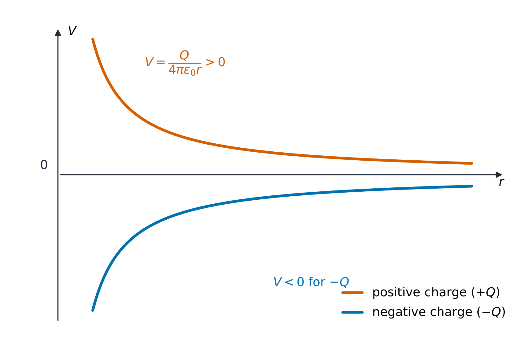
$$V=\frac{U}{q}=\frac{kQ}{r}.$$The potential difference (voltage) 电压 between two points is the work per unit charge to move between them: $\Delta V=\dfrac{\Delta U}{q}$, and $U=qV$. Positive charges move from high to low potential on their own. Because potential is a scalar, adding the potentials from several charges is much easier than adding field vectors.The potential near a point charge varies as 1/r Vocabulary · 어휘 Train · 연습하기English 한국어 Electric potential/ɪˈlektrɪk pəˈtenʃl/ 전기ポテン셜 potential difference/pəˈtenʃl ˈdɪfrəns/ 전위차 10.6
Capacitors
Syllabus
EnglishLearning Objective 10.6.A: Describe the physical properties of a parallel-plate capacitor.
- 10.6.A.1 A parallel-plate capacitor consists of two separated parallel conducting surfaces that can hold equal amounts of charge with opposite signs.
- 10.6.A.2 Capacitance relates the magnitude of the charge stored on each plate to the electric potential difference created by the separation of those charges.
- Equation: $C = \dfrac{Q}{\Delta V}$
- 10.6.A.2.i The capacitance of a capacitor depends only on the physical properties of the capacitor, such as the capacitor's shape and the material used to separate the plates.
- 10.6.A.2.ii The capacitance of a parallel-plate capacitor is proportional to the area of one of its plates and inversely proportional to the distance between its plates. The constant of proportionality is the product of the dielectric constant, $\kappa$, of the material between the plates and the electric permittivity of free space, $\varepsilon_0$.
- Equation: $C = \kappa\varepsilon_0\dfrac{A}{d}$
- 10.6.A.3 The electric field between two charged parallel plates with uniformly distributed electric charge, such as in a parallel-plate capacitor, is constant in both magnitude and direction, except near the edges of the plates.
- 10.6.A.3.i The magnitude of the electric field between two charged parallel plates, where the plate separation is much smaller than the dimensions of the plates, can be described with the equation
- Equation: $E_C = \dfrac{Q}{\kappa\varepsilon_0 A}$
- 10.6.A.3.ii A charged particle between two oppositely charged parallel plates undergoes constant acceleration and therefore its motion shares characteristics with the projectile motion of an object with mass in the gravitational field near Earth's surface.
- 10.6.A.3.i The magnitude of the electric field between two charged parallel plates, where the plate separation is much smaller than the dimensions of the plates, can be described with the equation
- 10.6.A.4 The electric potential energy stored in a capacitor is equal to the work done by an external force to separate that amount of charge on the capacitor.
- 10.6.A.5 The electric potential energy stored in a capacitor is described by the equation
- Equation: $U_C = \dfrac{1}{2}Q\Delta V$
- 10.6.A.6 Adding a dielectric between two plates of a capacitor changes the capacitance of the capacitor and induces an electric field in the dielectric in the opposite direction to the field between the plates.
Boundary statement: While other shapes are also able to separate charges, only the analysis and descriptions of parallel-plate capacitors are required for AP Physics 2. Edge effects will be ignored unless explicitly stated otherwise.
한국어학습 목표 10.6.A: 평판 콘덴서의 물리적 특성을 설명하시오.
- 10.6.A.1 평판 콘덴서는 서로 분리된 평행한 두 도체 면으로 구성되어 있으며, 크기는 같고 부호가 반대인 전하량을 저장할 수 있다.
- 10.6.A.2 정전용량은 각 판에 저장된 전하량의 크기와 그 전하들의 분리에 의해 생성된 전기적ポ텐셜 차이 사이의 관계를 나타낸다.
- 식: $C = \dfrac{Q}{\Delta V}$
- 10.6.A.2.i 콘덴서의 정전용량은 콘덴서의 형상과 판을 분리하는 데 사용되는 소재와 같은 콘덴서의 물리적 특성에만 의존한다.
- 10.6.A.2.ii 평판 콘덴서의 정전용량은 판 중 하나의 면적에 비례하고, 판 사이의 거리에 반비례한다. 이 비례 상수는 판 사이의 소재의 유전율 $\kappa$과 진공의 전기유전율 $\varepsilon_0$의 곱이다.
- 식: $C = \kappa\varepsilon_0\dfrac{A}{d}$
- 10.6.A.3 평판 콘덴서와 같이 균일하게 분포된 전하를 가진 두 전하를 띤 평판 사이의 전기장은 판 가장자리 근처를 제외하면 크기와 방향이 일정하다.
- 10.6.A.3.i 판 간격이 판의 치수에 비해 훨씬 작은 두 전하를 띤 평판 사이의 전기장 크기는 다음 식으로 묘사할 수 있다.
- 식: $E_C = \dfrac{Q}{\kappa\varepsilon_0 A}$
- 10.6.A.3.ii 반대의 전하를 띤 두 평판 사이에 있는 전하 입자는 일정한 가속도를 받으며, 따라서 그 운동은 지구 표면 근처 중력장 내 질량을 가진 물체의 포물선 운동과 유사한 특징을 가진다.
- 10.6.A.3.i 판 간격이 판의 치수에 비해 훨씬 작은 두 전하를 띤 평판 사이의 전기장 크기는 다음 식으로 묘사할 수 있다.
- 10.6.A.4 콘덴서에 저장된 전기적ポ텐셜 에너지는 콘덴서에 해당 양의 전하를 분리하기 위해 외부력이 행한 일과 같다.
- 10.6.A.5 콘덴서에 저장된 전기적ポ텐셜 에너지는 다음 식으로 묘사된다.
- 식: $U_C = \dfrac{1}{2}Q\Delta V$
- 10.6.A.6 콘덴서의 두 판 사이에 유전체를 추가하면 콘덴서의 정전용량이 변화하고, 유전체 내부에 판 사이의 장과 반대 방향으로 전기장이 유도된다.
경계 문구: 다른 형태도 전하를 분리할 수 있으나, AP 물리학 2에서는 평판 콘덴서에 대한 분석과 묘사만 요구하며, 명시되지 않는 한 가장자리 효과(edge effects)는 무시한다.
Source: College Board AP Course and Exam Description · 출처: College Board AP Course and Exam Description
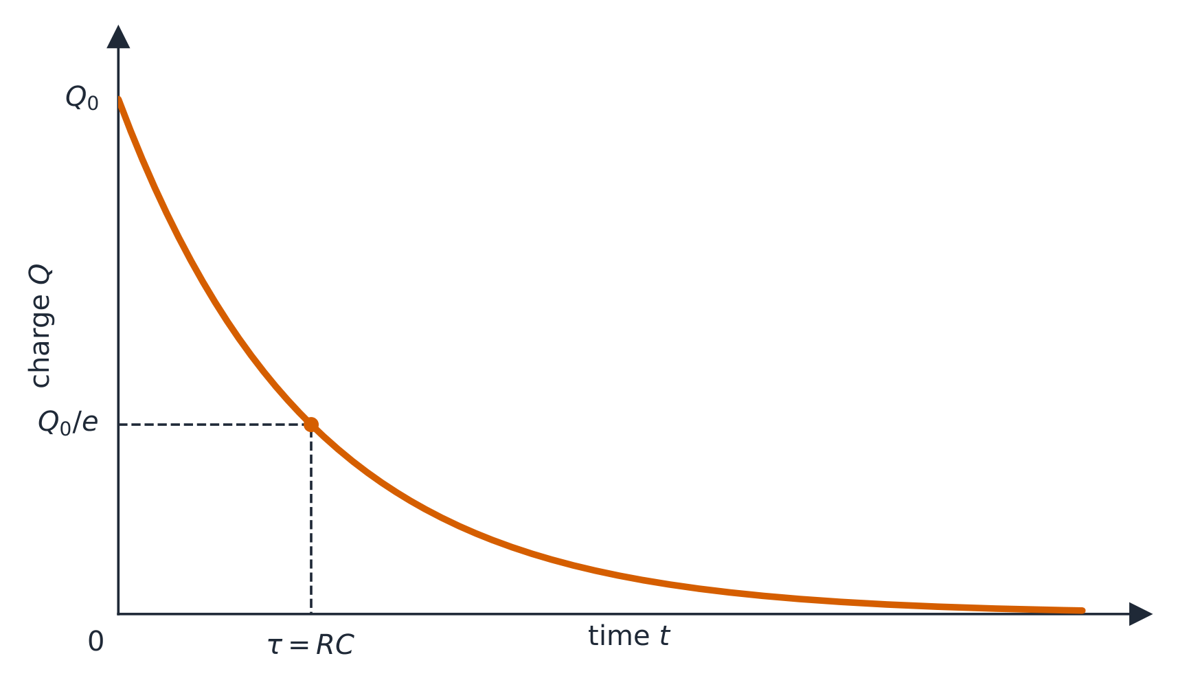
Discharging a capacitor: τ = RC Charging a capacitor (RC) A capacitor 电容器 stores charge and energy on two conductors separated by a gap. Its capacitance 电容 relates charge to voltage:
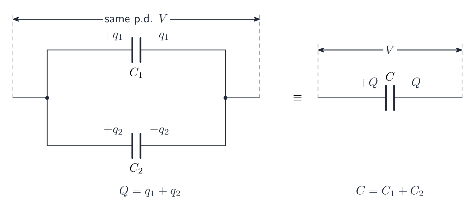
$$C=\frac{Q}{V},$$and the stored energy is $U=\tfrac{1}{2}CV^2$. Capacitance depends on the plates' geometry and the material between them, not on the charge placed on it.Capacitors in parallel share the same p.d., and their charges add Worked example. A $100\ \mu\text{F}$ capacitor is charged to $12\ \text{V}$. It holds $Q=CV=100\times10^{-6}\times12=1.2\times10^{-3}\ \text{C}$ of charge and stores $U=\tfrac12 CV^2=\tfrac12\times100\times10^{-6}\times12^2=7.2\times10^{-3}\ \text{J}$ of energy.
Explore · 탐색하기Charge and discharge a capacitor · 콘덴서를 충전하고 방전하기
A capacitor stores charge on two plates. It fills and empties exponentially, set by the time constant $\tau = RC$ — bigger $R$ or $C$ means slower charging. · 콘덴서는 두 극판에 전하를 저장합니다. 이는 시간 상수 $\tau = RC$에 의해 결정되며 지수함수적으로 충전되고 방전됩니다. 더 큰 $R$ 또는 $C$일수록 충전 속도가 느립니다.
Vocabulary · 어휘 Train · 연습하기English 한국어 capacitor/kəˈpæsɪtə/ 콘덴서(축전기) capacitance/kəˈpæsɪtəns/ 정전용량 10.7
Conservation of Electric Energy
Syllabus
EnglishLearning Objective 10.7.A: Describe changes in energy in a system due to a difference in electric potential between two locations.
- 10.7.A.1 When a charged object moves between two locations with different electric potentials, the resulting change in the electric potential energy of the object-field system is given by the following equation.
- Equation: $\Delta U_E = q\Delta V$
- 10.7.A.2 The movement of a charged object between two points with different electric potentials results in a change in kinetic energy of the object consistent with the conservation of energy.
한국어학습 목표 10.7.A: 두 위치 간의 전기적 전위 차이로 인한 시스템 내 에너지 변화를 설명하시오.
- 10.7.A.1 전하를 띤 물체가 서로 다른 전기적 전위를 가진 두 위치 사이를 이동할 때, 이 물체-장 시스템의 전기적 전위 에너지 변화는 다음 식으로 주어진다.
- 식: $\Delta U_E = q\Delta V$
- 10.7.A.2 서로 다른 전기적 전위를 가진 두 지점 간에서 전하를 띤 물체의 이동은 에너지 보존 법칙에 따라 해당 물체의 운동 에너지 변화와 일치한다.
Source: College Board AP Course and Exam Description · 출처: College Board AP Course and Exam Description
Energy is conserved for charges just as for masses. A charge released in a field converts electric potential energy into kinetic energy:
$$q\,\Delta V=\tfrac{1}{2}mv^2 \quad(\text{gaining speed as it "falls" through a potential difference}).$$Worked example. An electron ($q=1.6\times10^{-19}\ \text{C}$, $m=9.1\times10^{-31}\ \text{kg}$) is accelerated from rest through a potential difference of $100\ \text{V}$. Its final speed is
$$v=\sqrt{\frac{2q\,\Delta V}{m}}=\sqrt{\frac{2\times1.6\times10^{-19}\times100}{9.1\times10^{-31}}}=5.9\times10^{6}\ \text{m/s}.$$This is exactly how the electron gun in an old television or an electron microscope works.10.7
Exam tips
- Coulomb's law and the point-charge field are inverse-square — doubling the separation makes the force (or field) four times smaller.
- Use magnitudes for the size of a force and decide direction from the signs; the field points the way a positive test charge would move.
- Potential ($V$) is a scalar so potentials from several charges simply add; the field ($E$) is a vector and must be added by direction.
- For a charge accelerated through a voltage use energy conservation $qV=\tfrac12 mv^2$.
- Capacitor relations: $C=Q/V$ (capacitance is fixed by geometry) and energy $U=\tfrac12 CV^2$.
- 10.1.A.1 Charge is a fundamental property of all matter.
-
11
Electric Circuits
Watch lesson · 수업 보기11.1
Electric Current
Syllabus
EnglishLearning Objective 11.1.A: Describe the movement of electric charges through a medium.
- 11.1.A.1 Current is the rate at which charge passes through a cross-sectional area of a wire.
- Equation: $I = \dfrac{\Delta q}{\Delta t}$
- 11.1.A.1.i Electric charge moves in a circuit in response to an electric potential difference, sometimes referred to as electromotive force, or $\mathrm{emf}$ ($\varepsilon$).
- 11.1.A.1.ii If the current is zero in a section of wire, the net motion of charge carriers in the wire is also zero, although individual charge carriers will not have zero speed.
- 11.1.A.2 Although current is not a vector quantity, it does have a direction. The direction of current is associated with what the motion of positive charge would be but not with any coordinate system in space.
- 11.1.A.2.i The direction of conventional current is chosen to be the direction in which positive charge would move.
- 11.1.A.2.ii In common circuits, current is actually due to the movement of electrons (negative charge carriers).
한국어학습 목표 11.1.A: 매질을 통한 전기전하의 움직임을 설명하시오.
- 11.1.A.1 전류는 도선의 단면적을 통과하는 전하의 흐름률이다.
- 식: $I = \dfrac{\Delta q}{\Delta t}$
- 11.1.A.1.i 전기전하는 전기적 전위차, 즉 기동력(emf) 또는 $\mathrm{emf}$ ($\varepsilon$)에 반응하여 회로를 통해 이동한다.
- 11.1.A.1.ii 도선의 한 구간에서 전류가 0인 경우, 도선 내 운반자의 순이동도 0이지만 개별 운반자의 속도는 0이 아니다.
- 11.1.A.2 전류는 벡터량이 아니지만 방향을 가진다. 전류의 방향은 양전하의 움직임이 될 방향과 관련되지만 공간상의 좌표계와는 무관하다.
- 11.1.A.2.i 통상 전류의 방향은 양전하가 움직일 것으로 가정된 방향으로 정해진다.
- 11.1.A.2.ii 일반적인 회로에서 전류는 실제로 전자(음전하 운반자)의 이동에 의해 발생한다.
Source: College Board AP Course and Exam Description · 출처: College Board AP Course and Exam Description
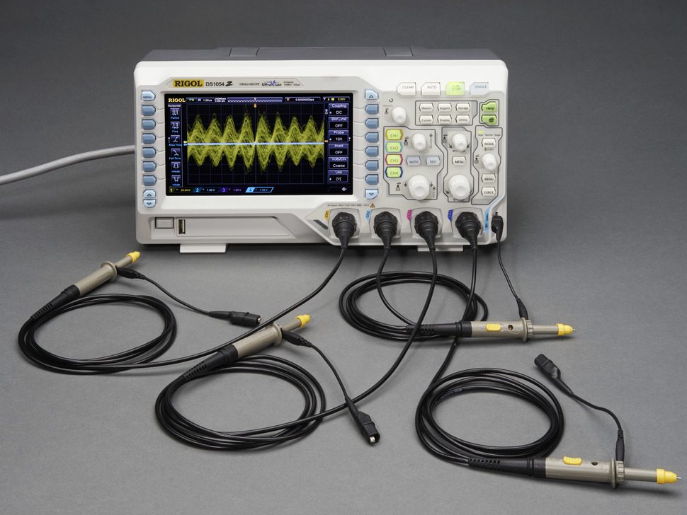
An oscilloscope: circuit behaviour over time is measured as voltage against time Electric current 电流 is the rate at which charge flows past a point, measured in amperes 安培 (A):
$$I=\frac{\Delta q}{\Delta t}.$$By convention, current points the way positive charge would move (opposite to the electrons in a wire). A steady current needs a complete loop and an energy source (a battery's electromotive force, or emf).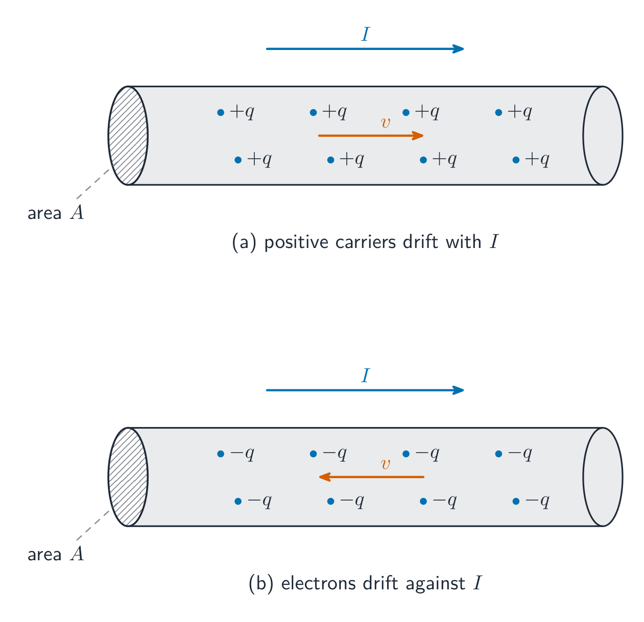
Charge carriers drift slowly through a conductor to make a current Vocabulary · 어휘 Train · 연습하기English 한국어 Electric current/ɪˈlektrɪk ˈkʌrənt/ 전류 amperes/ˈæmpeəz/ 암페어(Ampere) 11.2
Simple Circuits
Syllabus
EnglishLearning Objective 11.2.A: Describe the behavior of a circuit.
- 11.2.A.1 A circuit is composed of electrical loops, which may include circuit elements such as wires, batteries, resistors, lightbulbs, capacitors, switches, ammeters, and voltmeters.
- 11.2.A.2 A closed electrical loop is a closed path through which charges may flow.
- 11.2.A.2.i A closed circuit is one in which charges would be able to flow.
- 11.2.A.2.ii An open circuit is one in which charges would not be able to flow.
- 11.2.A.2.iii A short circuit is one in which charges would be able to flow with no change in potential difference.
- 11.2.A.3 A single circuit element may be part of multiple electrical loops.
- 11.2.A.4 Circuit schematics are representations used to describe and analyze electric circuits.
- 11.2.A.4.i The properties of an electric circuit are dependent on the physical arrangement of its constituent elements.
- 11.2.A.4.ii Circuit elements have common symbols that are used to create schematic diagrams. Variable elements are indicated by a diagonal strikethrough arrow across the standard symbol for that element. (Standard symbols: Battery, Bulb, Switch, Capacitor, Resistor, Ammeter, Voltmeter.)
Boundary statement: Unless otherwise specified, all circuit schematic diagrams will be drawn using conventional current.
한국어학습 목표 11.2.A: 회로의 동작을 설명하시오.
- 11.2.A.1 회로는 도선, 배터리, 저항기, 전구, 콘덴서, 스위치, 아머미터 및 볼트미터와 같은 회로 요소를 포함할 수 있는 전기 루프들로 구성된다.
- 11.2.A.2 폐회로( rumors circuit )는 전하가 흐를 수 있는 닫힌 경로이다.
- 11.2.A.2.i 폐회로는 전하가 흐를 수 있는 회로이다.
- 11.2.A.2.ii 개회로는 전하가 흐를 수 없는 회로이다.
- 11.2.A.2.iii 단락 회로는 전하가 전위차 변화 없이 흐를 수 있는 회로이다.
- 11.2.A.3 하나의 회로 요소가 여러 전기 루프의 일부가 될 수 있다.
- 11.2.A.4 회로도(schematic diagram)는 전기 회로를 서술하고 분석하기 위해 사용되는 표현법이다.
- 11.2.A.4.i 전기회로의 특성은 constituent 요소들의 물리적 배치에 의존한다.
- 11.2.A.4.ii 회로 요소에는 회로도 작성을 위해 사용되는 공통적인 기호가 있다. 가변 요소는 해당 요소의 표준 기호 위에 대각선 strikethrough 화살표로 표시된다. (표준 기호: 배터리, 전구, 스위치, 콘덴서, 저항기, 아머미터, 볼트미터.)
경계 명제: 별도 명시하지 않는 한 모든 회로도 그림은 통상 전류를 사용하여 그려진다.
Source: College Board AP Course and Exam Description · 출처: College Board AP Course and Exam Description
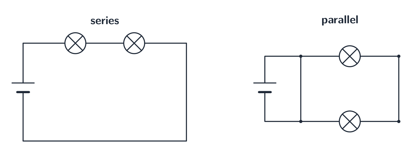
A circuit is a closed loop of conductors, a source (battery), and components. In a series 串联 path the same current flows through each element; in a parallel 并联 path the same voltage is across each branch. A circuit diagram uses standard symbols; reading it correctly is the first step of any circuit problem.
Components can be joined in series or in parallel 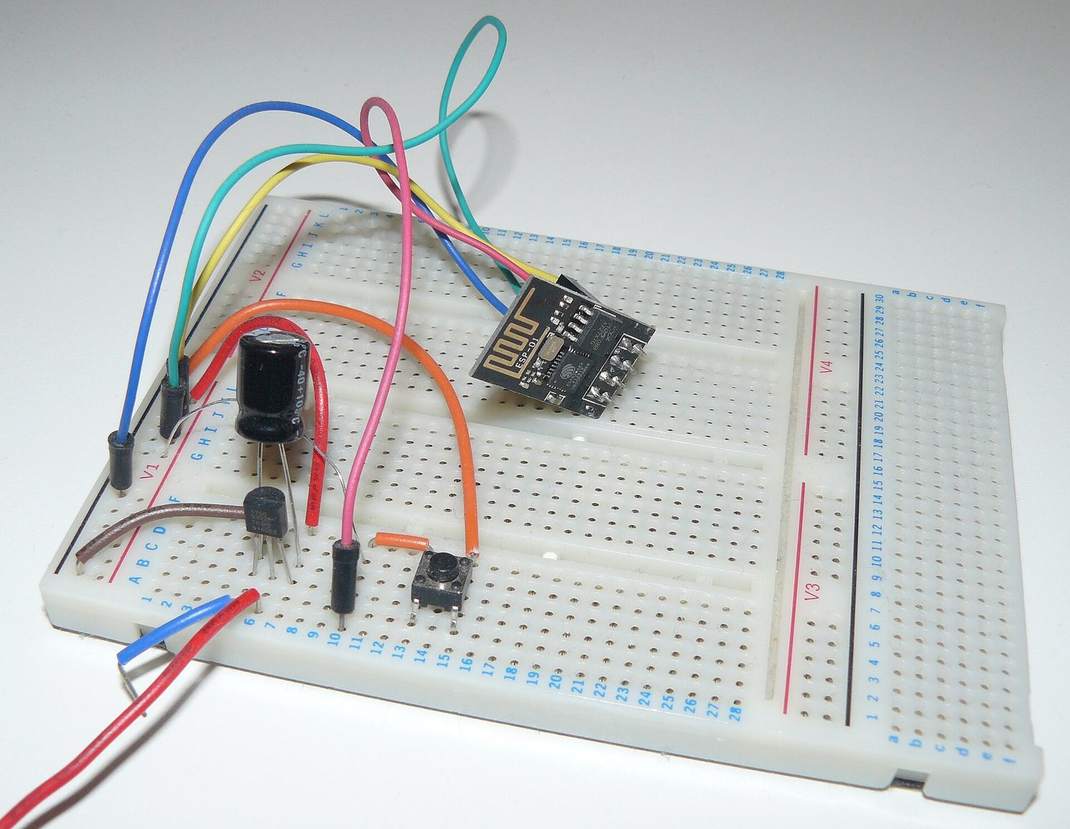
A real circuit: components pushed into a breadboard and joined by wires so current has a complete path Explore · 탐색하기Build series and parallel circuits · 직렬 및 병렬 회로 만들기
In series the same current flows through every bulb and voltage divides; in parallel each branch gets the full voltage. Switch mode to see the bulbs' brightness change. · 직렬 회로에서는 모든 전구를 통해 동일한 전류가 흐르고 전압이 분배됩니다. 병렬 회로에서는 각 가지에 전체 전압이 인가됩니다. 스위치 모드를 사용하여 전구의 밝기 변화를 확인하세요.
Vocabulary · 어휘 Train · 연습하기English 한국어 series/ˈsɪəriːz/ 직렬 parallel/ˈpærəlel/ 평행 11.3
Resistance, Resistivity, and Ohm's Law
Syllabus
EnglishLearning Objective 11.3.A: Describe the resistance of an object using physical properties of that object.
- 11.3.A.1 Resistance is a measure of the degree to which an object opposes the movement of electric charge.
- 11.3.A.2 The resistance of a resistor with uniform geometry is proportional to its resistivity and length and is inversely proportional to its cross-sectional area.
- Equation: $R = \dfrac{\rho \ell}{A}$
- 11.3.A.2.i Resistivity is a fundamental property of a material that depends on its atomic and molecular structure and quantifies how strongly the material opposes the motion of electric charge.
- 11.3.A.2.ii The resistivity of a conductor typically increases with temperature.
Learning Objective 11.3.B: Describe the electrical characteristics of elements of a circuit.
- 11.3.B.1 Ohm's law relates current, resistance, and potential difference across a conductive element of a circuit.
- Equation: $I = \dfrac{\Delta V}{R}$
- 11.3.B.1.i Materials that obey Ohm's law have constant resistance for all currents and are called ohmic materials.
- 11.3.B.1.ii The resistivity of an ohmic material is constant regardless of temperature.
- 11.3.B.1.iii Resistors can also convert electrical energy to thermal energy, which may change the temperature of both the resistor and the resistor's environment.
- 11.3.B.1.iv The resistance of an ohmic circuit element can be determined from the slope of a graph of the current in the element as a function of the potential difference across the element.
한국어학습 목표 11.3.A: 물체의 물리적 성질을 사용하여 그 물체의 저항을 설명하시오.
- 11.3.A.1 저항은 물체가 전기전하의 이동을 얼마나 저해하는지를 나타내는 척도이다.
- 11.3.A.2 균일한 기하학적 형상을 가진 저항기의 저항은 그 저항율과 길이에 비례하며, 단면적에 반비례한다.
- 식: $R = \dfrac{\rho \ell}{A}$
- 11.3.A.2.i 저항율은 물질의 원자 및 분자 구조에 의존하는 물질의 근본적 성질로서, 물질이 전기전하의 운동을 얼마나 강하게 저해하는지를 정량화한다.
- 11.3.A.2.ii 도체의 저항율은 일반적으로 온도가 올라갈수록 증가한다.
학습 목표 11.3.B: 회로 요소의 전기적 특성을 설명하시오.
- 11.3.B.1 옴의 법칙은 회로의 전도성 요소에 흐르는 전류, 저항, 그리고 전위차 사이의 관계를 나타낸다.
- 식: $I = \dfrac{\Delta V}{R}$
- 11.3.B.1.i 옴의 법칙을 따르는 물질은 모든 전류에 대해 일정한 저항을 가지며 이를 옴 물질(Ohmic material)이라 한다.
- 11.3.B.1.ii 옴 물질의 저항율은 온도에 관계없이 일정하다.
- 11.3.B.1.iii 저항기는 또한 전기 에너지를 열에너지로 변환할 수 있으며, 이는 저항기 자체와 주변 환경의 온도 변화를 초래할 수 있다.
- 11.3.B.1.iv 옴 회로 요소의 저항은 해당 요소에 걸린 전위차에 대한 요소 내 전류의 그래프 기울기로부터 결정할 수 있다.
Source: College Board AP Course and Exam Description · 출처: College Board AP Course and Exam Description
Resistance 电阻 $R$ opposes current, measured in ohms. Ohm's law 欧姆定律 links the three key quantities:
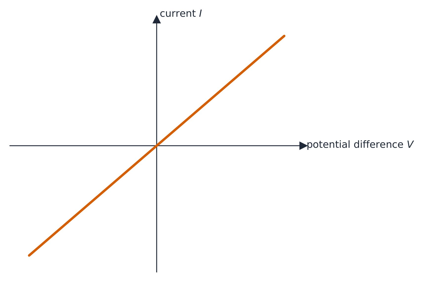
$$V=IR.$$A component's resistance depends on the material's resistivity 电阻率 $\rho$, its length, and its cross-sectional area: $R=\dfrac{\rho L}{A}$ – longer and thinner means more resistance.The I-V line of an ohmic conductor is straight through the origin Worked example. A $2.0\ \text{A}$ current flows through a $6.0\ \Omega$ resistor. The voltage across it is $V=IR=2.0\times6.0=12\ \text{V}$.
Explore · 탐색하기Apply Ohm's law · 옴의 법칙 적용하기
Ohm's law $V=IR$: for a fixed resistance, current is proportional to voltage. Raise the resistance and the same voltage pushes less current. · 옴의 법칙 $V=IR$: 저항이 일정할 때 전류는 전압에 비례합니다. 저항을 높이면 동일한 전압에서도 흐르는 전류는 줄어듭니다.
Vocabulary · 어휘 Train · 연습하기English 한국어 Resistance/rɪˈzɪstəns/ Resistance Ohm's law/əʊmz lɔː/ 옴의 법칙 resistivity/ˌriːzɪˈstɪvəti/ 비저항율 11.4
Electric Power
Syllabus
EnglishLearning Objective 11.4.A: Describe the transfer of energy into, out of, or within an electric circuit, in terms of power.
- 11.4.A.1 The rate at which energy is transferred, converted, or dissipated by a circuit element depends on the current in the element and the electric potential difference across it.
- Equation: $P = I \Delta V$
- Equation (derived): $P = I^2 R = \dfrac{(\Delta V)^2}{R}$
- 11.4.A.2 The brightness of a bulb increases with power, so power can be used to qualitatively predict the brightness of bulbs in a circuit.
한국어학습 목표 11.4.A: power를 사용하여 전기회로로 들어가는, 나가는, 혹은 내부에서의 에너지 전달을 설명하시오.
- 11.4.A.1 회로 요소에 의해 전달, 변환, 또는 소모되는 에너지의 속도는 해당 요소의 전류와 요소에 걸린 전기적 전위차에 의존한다.
- 식: $P = I \Delta V$
- 식(유도): $P = I^2 R = \dfrac{(\Delta V)^2}{R}$
- 11.4.A.2 전구의 밝기는 power에 따라 증가하므로, power를 사용하여 회로 내 전구의 밝기를 질적으로 예측할 수 있다.
Source: College Board AP Course and Exam Description · 출처: College Board AP Course and Exam Description
Electric power 电功率 is the rate a component converts electrical energy (to heat, light, motion):
$$P=IV=I^2R=\frac{V^2}{R}.$$Pick the form that uses the quantities you know. A resistor's power all becomes heat.Worked example. The $6.0\ \Omega$ resistor above, carrying $2.0\ \text{A}$, dissipates $P=I^2R=2.0^2\times6.0=24\ \text{W}$ – equivalently $P=IV=2.0\times12=24\ \text{W}$.
A light bulb 灯泡 is just a resistor that glows, and its brightness 亮度 rises with the power it dissipates. So to rank bulbs, compare their power. In a series string every bulb carries the same current, so by $P=I^2R$ the bulb with the largest resistance is brightest; wired in parallel every bulb gets the full battery voltage, so by $P=V^2/R$ the bulb with the smallest resistance is brightest.
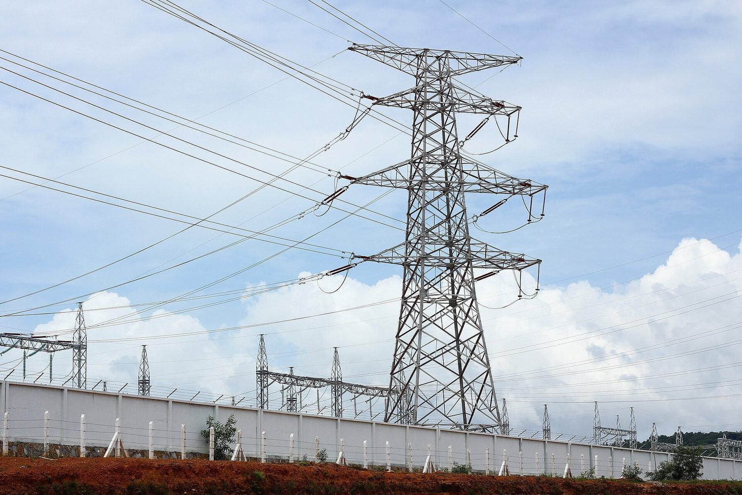
High-voltage power lines: electrical power is transmitted as high voltage so current (and I²R loss) stays low Explore · 탐색하기Read an I-V characteristic · I-V 특성 곡선 읽기
Power is $P=IV$. A resistor's I-V line is straight, but a lamp curves as it heats and its resistance rises. The area under I-V relates to the energy delivered. · 전력은 $P=IV$입니다. 저항기의 I-V 선은 직선이지만, 전구는 발열하며 저항이 증가함에 따라 곡선을 그립니다. I-V 곡선 아래 면적은 전달된 에너지와 관련이 있습니다.
Vocabulary · 어휘 Train · 연습하기English 한국어 Electric power/ɪˈlektrɪk ˈpaʊə/ 전기력 light bulb/laɪt bʌlb/ 전구 brightness/ˈbraɪtnəs/ 밝기 11.5
Compound DC Circuits

Syllabus
EnglishLearning Objective 11.5.A: Describe the equivalent resistance of multiple resistors connected in a circuit.
- 11.5.A.1 Circuit elements may be connected in series and/or in parallel.
- 11.5.A.1.i A series connection is one in which any charge passing through one circuit element must proceed through all elements in that connection and has no other path available. The current in each element in series must be the same.
- 11.5.A.1.ii A parallel connection is one in which charges may flow through one of two or more paths. Across each path, the potential difference is the same.
- 11.5.A.2 A collection of resistors in a circuit may be analyzed as though it were a single resistor with an equivalent resistance $R_{\text{eq}}$.
- 11.5.A.2.i The equivalent resistance of a set of resistors in series is the sum of the individual resistances.
- Equation: $R_{\text{eq},s} = \sum_i R_i$
- 11.5.A.2.ii The inverse of the equivalent resistance of a set of resistors connected in parallel is equal to the sum of the inverses of the individual resistances.
- Equation: $\dfrac{1}{R_{\text{eq},p}} = \sum_i \dfrac{1}{R_i}$
- 11.5.A.2.iii When resistors are connected in parallel, the number of paths available to charges increases, and the equivalent resistance of the group of resistors decreases.
- 11.5.A.2.i The equivalent resistance of a set of resistors in series is the sum of the individual resistances.
Learning Objective 11.5.B: Describe a circuit with resistive wires and a battery with internal resistance.
- 11.5.B.1 Ideal batteries have negligible internal resistance. Ideal wires have negligible resistance.
- 11.5.B.1.i The resistance of wires that are good conductors may normally be neglected, because their resistance is much smaller than that of other elements of a circuit.
- 11.5.B.1.ii The resistance of wires may only be neglected if the circuit contains other elements that do have resistance.
- 11.5.B.1.iii The potential difference a battery would supply if it were ideal is the potential difference measured across the terminals when there is no current in the battery and is sometimes referred to as its $\mathrm{emf}$ ($\varepsilon$).
- 11.5.B.2 The internal resistance of a nonideal battery may be treated as the resistance of a resistor in series with an ideal battery and the remainder of the circuit.
- 11.5.B.3 When there is current in a nonideal battery with internal resistance $r$, the potential difference across the terminals of the battery is reduced relative to the potential difference when there is no current in the battery.
- Equation (derived): $\Delta V_{\text{terminal}} = \varepsilon - Ir$
Learning Objective 11.5.C: Describe the measurement of current and potential difference in a circuit.
- 11.5.C.1 Ammeters are used to measure current at a specific point in a circuit.
- 11.5.C.1.i Ammeters must be connected in series with the element in which current is being measured.
- 11.5.C.1.ii Ideal ammeters have zero resistance so that they do not affect the current in the element that they are in series with.
- 11.5.C.2 Voltmeters are used to measure electric potential difference between two points in a circuit.
- 11.5.C.2.i Voltmeters must be connected in parallel with the element across which potential difference is being measured.
- 11.5.C.2.ii Ideal voltmeters have an infinite resistance so that no charge flows through them.
- 11.5.C.3 Nonideal ammeters and voltmeters will change the properties of the circuit being measured.
Boundary statement: AP Physics 2 only expects students to qualitatively discuss how a nonideal ammeter or voltmeter will affect the results of measurements. Unless otherwise stated, all batteries, wires, and meters are assumed to be ideal.
Boundary statement: Circuits with batteries of different potential differences connected in parallel will not be assessed.
한국어학습 목표 11.5.A: 회로에 연결된 여러 저항기의 등가 저항을 설명하시오.
- 11.5.A.1 회로 요소는 직렬 및/또는 병렬로 연결될 수 있다.
- 11.5.A.1.i 직렬 연결은 하나의 회로 요소를 통과한 전하가 반드시 해당 연결의 모든 요소를 지나야 하며 다른 경로를 사용할 수 없는 경우이다. 직렬로 연결된 각 요소의 전류는 동일해야 한다.
- 11.5.A.1.ii 병렬 연결은 전하가 두 개 이상의 경로 중 하나를 통해 흐를 수 있는 연결 방식입니다. 각 경로의 양단 간 전위차는 동일합니다.
- 11.5.A.2 회로 내 저항기의 집합은 등가 저항 $R_{\text{eq}}$을 가진 단일 저항기로 처리하여 분석할 수 있습니다.
- 11.5.A.2.i 직렬로 연결된 저항기 집합의 등가 저항은 개별 저항들의 합과 같습니다.
- 식: $R_{\text{eq},s} = \sum_i R_i$
- 11.5.A.2.ii 병렬로 연결된 저항기 집합의 등가 저항의 역수는 개별 저항들의 역수의 합과 같습니다.
- 식: $\dfrac{1}{R_{\text{eq},p}} = \sum_i \dfrac{1}{R_i}$
- 11.5.A.2.iii 저항기를 병렬로 연결하면 전하가 흐를 수 있는 경로 수가 증가하고, 저항기 집합의 등가 저항은 감소합니다.
- 11.5.A.2.i 직렬로 연결된 저항기 집합의 등가 저항은 개별 저항들의 합과 같습니다.
학습 목표 11.5.B: 저항성 도선과 내부 저항이 있는 배터리가 포함된 회로를 설명하십시오.
- 11.5.B.1 이상적인 배터리는 내부 저항이 무시할 수 있을 정도로 작습니다. 이상적인 도선은 저항이 무시할 수 있을 정도로 작습니다.
- 11.5.B.1.i 좋은 도체인 도선의 저항은 일반적으로 회로의 다른 요소에 비해 훨씬 작으므로 무시할 수 있습니다.
- 11.5.B.1.ii 회로에 저항이 있는 다른 요소가 포함되어 있을 때만 도선의 저항을 무시할 수 있습니다.
- 11.5.B.1.iii 배터리가 이상적일 경우 공급할 전위차는 배터리에 전류가 흐르지 않을 때 단자 간에 측정되는 전위차이며, 이를 때때로 $\mathrm{emf}$($\varepsilon$)이라고 부릅니다.
- 11.5.B.2 비이상적인 배터리의 내부 저항은 이상적인 배터리와 회로의 나머지 부분에 직렬로 연결된 저항기의 저항으로 간주할 수 있습니다.
- 11.5.B.3 내부 저항 $r$이 있는 비이상적인 배터리에 전류가 흐를 때, 배터리의 단자 간 전위차는 배터리에 전류가 흐르지 않을 때의 전위차보다 낮아집니다.
- 식(유도): $\Delta V_{\text{terminal}} = \varepsilon - Ir$
학습 목표 11.5.C: 회로 내 전류 및 전위차의 측정 방법을 설명하십시오.
- 11.5.C.1 아메트르는 회로의 특정 지점에서의 전류를 측정하는 데 사용됩니다.
- 11.5.C.1.i 아메트는 전류를 측정하려는 요소와 직렬로 연결되어야 합니다.
- 11.5.C.1.ii 이상적인 아메트는 직렬로 연결된 요소의 전류에 영향을 주지 않도록 저항이 0이어야 합니다.
- 11.5.C.2 볼트미터는 회로의 두 점 사이의 전기 전위차를 측정하는 데 사용됩니다.
- 11.5.C.2.i 볼트미터는 전위차를 측정하려는 요소와 병렬로 연결되어야 합니다.
- 11.5.C.2.ii 이상적인 볼트미터는 전하가 흐르지 않도록 저항이 무한대여야 합니다.
- 11.5.C.3 비이상적인 아메트와 볼트미터는 측정 대상 회로의 특성을 변경할 수 있습니다.
범위 statement: AP 물리학 2에서는 비이상적인 아메트 또는 볼트미터가 측정 결과에 미치는 영향을 정성적으로 논하는 것만 학생들에게 요구합니다. 별도로 명시되지 않는 한 모든 배터리, 도선 및 계기는 이상적인 것으로 가정합니다.
범위 statement: 서로 다른 전위차를 가진 배터리를 병렬로 연결한 회로는 평가 대상이 아닙니다.
Source: College Board AP Course and Exam Description · 출처: College Board AP Course and Exam Description
Combine resistors to find an equivalent resistance 等效电阻:
Resistors in series add to a single equivalent resistance - Series: $R_{\text{eq}}=R_1+R_2+\cdots$ (resistances add).
- Parallel: $\dfrac{1}{R_{\text{eq}}}=\dfrac{1}{R_1}+\dfrac{1}{R_2}+\cdots$ (the total is less than the smallest).
Reduce the network step by step to find the total current from the battery, then work back to each element.
Worked example. A $12\ \text{V}$ battery drives a $4.0\ \Omega$ and a $12\ \Omega$ resistor in parallel. First combine them: $\dfrac{1}{R_{\text{eq}}}=\dfrac14+\dfrac{1}{12}=\dfrac{4}{12}\Rightarrow R_{\text{eq}}=3.0\ \Omega$. The total current from the battery is $I=\dfrac{V}{R_{\text{eq}}}=\dfrac{12}{3.0}=4.0\ \text{A}$, which splits so that the smaller resistor carries the larger share ($3.0\ \text{A}$ through the $4\ \Omega$, $1.0\ \text{A}$ through the $12\ \Omega$).
Vocabulary · 어휘 Train · 연습하기English 한국어 equivalent resistance/ɪˈkwɪvələnt rɪˈzɪstəns/ 등가 저항 11.5
Measuring Current and Voltage
Syllabus
EnglishLearning Objective 11.5.A: Describe the equivalent resistance of multiple resistors connected in a circuit.
- 11.5.A.1 Circuit elements may be connected in series and/or in parallel.
- 11.5.A.1.i A series connection is one in which any charge passing through one circuit element must proceed through all elements in that connection and has no other path available. The current in each element in series must be the same.
- 11.5.A.1.ii A parallel connection is one in which charges may flow through one of two or more paths. Across each path, the potential difference is the same.
- 11.5.A.2 A collection of resistors in a circuit may be analyzed as though it were a single resistor with an equivalent resistance $R_{\text{eq}}$.
- 11.5.A.2.i The equivalent resistance of a set of resistors in series is the sum of the individual resistances.
- Equation: $R_{\text{eq},s} = \sum_i R_i$
- 11.5.A.2.ii The inverse of the equivalent resistance of a set of resistors connected in parallel is equal to the sum of the inverses of the individual resistances.
- Equation: $\dfrac{1}{R_{\text{eq},p}} = \sum_i \dfrac{1}{R_i}$
- 11.5.A.2.iii When resistors are connected in parallel, the number of paths available to charges increases, and the equivalent resistance of the group of resistors decreases.
- 11.5.A.2.i The equivalent resistance of a set of resistors in series is the sum of the individual resistances.
Learning Objective 11.5.B: Describe a circuit with resistive wires and a battery with internal resistance.
- 11.5.B.1 Ideal batteries have negligible internal resistance. Ideal wires have negligible resistance.
- 11.5.B.1.i The resistance of wires that are good conductors may normally be neglected, because their resistance is much smaller than that of other elements of a circuit.
- 11.5.B.1.ii The resistance of wires may only be neglected if the circuit contains other elements that do have resistance.
- 11.5.B.1.iii The potential difference a battery would supply if it were ideal is the potential difference measured across the terminals when there is no current in the battery and is sometimes referred to as its $\mathrm{emf}$ ($\varepsilon$).
- 11.5.B.2 The internal resistance of a nonideal battery may be treated as the resistance of a resistor in series with an ideal battery and the remainder of the circuit.
- 11.5.B.3 When there is current in a nonideal battery with internal resistance $r$, the potential difference across the terminals of the battery is reduced relative to the potential difference when there is no current in the battery.
- Equation (derived): $\Delta V_{\text{terminal}} = \varepsilon - Ir$
Learning Objective 11.5.C: Describe the measurement of current and potential difference in a circuit.
- 11.5.C.1 Ammeters are used to measure current at a specific point in a circuit.
- 11.5.C.1.i Ammeters must be connected in series with the element in which current is being measured.
- 11.5.C.1.ii Ideal ammeters have zero resistance so that they do not affect the current in the element that they are in series with.
- 11.5.C.2 Voltmeters are used to measure electric potential difference between two points in a circuit.
- 11.5.C.2.i Voltmeters must be connected in parallel with the element across which potential difference is being measured.
- 11.5.C.2.ii Ideal voltmeters have an infinite resistance so that no charge flows through them.
- 11.5.C.3 Nonideal ammeters and voltmeters will change the properties of the circuit being measured.
Boundary statement: AP Physics 2 only expects students to qualitatively discuss how a nonideal ammeter or voltmeter will affect the results of measurements. Unless otherwise stated, all batteries, wires, and meters are assumed to be ideal.
Boundary statement: Circuits with batteries of different potential differences connected in parallel will not be assessed.
한국어학습 목표 11.5.A: 회로에 연결된 여러 저항기의 등가 저항을 설명하시오.
- 11.5.A.1 회로 요소는 직렬 및/또는 병렬로 연결될 수 있다.
- 11.5.A.1.i 직렬 연결은 하나의 회로 요소를 통과한 전하가 반드시 해당 연결의 모든 요소를 지나야 하며 다른 경로를 사용할 수 없는 경우이다. 직렬로 연결된 각 요소의 전류는 동일해야 한다.
- 11.5.A.1.ii 병렬 연결은 전하가 두 개 이상의 경로 중 하나를 통해 흐를 수 있는 연결 방식입니다. 각 경로의 양단 간 전위차는 동일합니다.
- 11.5.A.2 회로 내 저항기의 집합은 등가 저항 $R_{\text{eq}}$을 가진 단일 저항기로 처리하여 분석할 수 있습니다.
- 11.5.A.2.i 직렬로 연결된 저항기 집합의 등가 저항은 개별 저항들의 합과 같습니다.
- 식: $R_{\text{eq},s} = \sum_i R_i$
- 11.5.A.2.ii 병렬로 연결된 저항기 집합의 등가 저항의 역수는 개별 저항들의 역수의 합과 같습니다.
- 식: $\dfrac{1}{R_{\text{eq},p}} = \sum_i \dfrac{1}{R_i}$
- 11.5.A.2.iii 저항기를 병렬로 연결하면 전하가 흐를 수 있는 경로 수가 증가하고, 저항기 집합의 등가 저항은 감소합니다.
- 11.5.A.2.i 직렬로 연결된 저항기 집합의 등가 저항은 개별 저항들의 합과 같습니다.
학습 목표 11.5.B: 저항성 도선과 내부 저항이 있는 배터리가 포함된 회로를 설명하십시오.
- 11.5.B.1 이상적인 배터리는 내부 저항이 무시할 수 있을 정도로 작습니다. 이상적인 도선은 저항이 무시할 수 있을 정도로 작습니다.
- 11.5.B.1.i 좋은 도체인 도선의 저항은 일반적으로 회로의 다른 요소에 비해 훨씬 작으므로 무시할 수 있습니다.
- 11.5.B.1.ii 회로에 저항이 있는 다른 요소가 포함되어 있을 때만 도선의 저항을 무시할 수 있습니다.
- 11.5.B.1.iii 배터리가 이상적일 경우 공급할 전위차는 배터리에 전류가 흐르지 않을 때 단자 간에 측정되는 전위차이며, 이를 때때로 $\mathrm{emf}$($\varepsilon$)이라고 부릅니다.
- 11.5.B.2 비이상적인 배터리의 내부 저항은 이상적인 배터리와 회로의 나머지 부분에 직렬로 연결된 저항기의 저항으로 간주할 수 있습니다.
- 11.5.B.3 내부 저항 $r$이 있는 비이상적인 배터리에 전류가 흐를 때, 배터리의 단자 간 전위차는 배터리에 전류가 흐르지 않을 때의 전위차보다 낮아집니다.
- 식(유도): $\Delta V_{\text{terminal}} = \varepsilon - Ir$
학습 목표 11.5.C: 회로 내 전류 및 전위차의 측정 방법을 설명하십시오.
- 11.5.C.1 아메트르는 회로의 특정 지점에서의 전류를 측정하는 데 사용됩니다.
- 11.5.C.1.i 아메트는 전류를 측정하려는 요소와 직렬로 연결되어야 합니다.
- 11.5.C.1.ii 이상적인 아메트는 직렬로 연결된 요소의 전류에 영향을 주지 않도록 저항이 0이어야 합니다.
- 11.5.C.2 볼트미터는 회로의 두 점 사이의 전기 전위차를 측정하는 데 사용됩니다.
- 11.5.C.2.i 볼트미터는 전위차를 측정하려는 요소와 병렬로 연결되어야 합니다.
- 11.5.C.2.ii 이상적인 볼트미터는 전하가 흐르지 않도록 저항이 무한대여야 합니다.
- 11.5.C.3 비이상적인 아메트와 볼트미터는 측정 대상 회로의 특성을 변경할 수 있습니다.
범위 statement: AP 물리학 2에서는 비이상적인 아메트 또는 볼트미터가 측정 결과에 미치는 영향을 정성적으로 논하는 것만 학생들에게 요구합니다. 별도로 명시되지 않는 한 모든 배터리, 도선 및 계기는 이상적인 것으로 가정합니다.
범위 statement: 서로 다른 전위차를 가진 배터리를 병렬로 연결한 회로는 평가 대상이 아닙니다.
Source: College Board AP Course and Exam Description · 출처: College Board AP Course and Exam Description
Two meters read a circuit. An ammeter 电流表 measures the current at a point, so it must be wired in series – the current you want to measure has to flow through it. A voltmeter 电压表 measures the potential difference between two points, so it is wired in parallel, bridging across the component whose voltage you want.
For a meter to read the true value it must barely disturb the circuit:
- an ideal ammeter has zero resistance, so putting it in series does not reduce the current it reads;
- an ideal voltmeter has infinite resistance, so almost no current is diverted through it.
A real, nonideal 非理想 meter is imperfect: a real ammeter has a small resistance (it slightly lowers the current), and a real voltmeter lets a little current leak through (it slightly lowers the voltage it reads). So connecting any meter changes, a little, the very quantity it is measuring.
Vocabulary · 어휘 Train · 연습하기English 한국어 ammeter/ˈæmiːtə/ 전류계 voltmeter/ˈvəʊltmiːtə/ 전압계 nonideal/ˌnɒnaɪˈdɪəl/ 비이상적 11.6
Kirchhoff's Loop Rule
Syllabus
EnglishLearning Objective 11.6.A: Describe a circuit or elements of a circuit by applying Kirchhoff's loop rule.
- 11.6.A.1 Energy changes in simple electrical circuits may be represented in terms of charges moving through electric potential differences within circuit elements.
- Equation: $\Delta U_E = q \Delta V$
- 11.6.A.2 Kirchhoff's loop rule is a consequence of the conservation of energy.
- 11.6.A.3 Kirchhoff's loop rule states that the sum of potential differences across all circuit elements in a single closed loop must equal zero.
- Equation: $\sum \Delta V = 0$
- 11.6.A.4 The values of electric potential at points in a circuit can be represented by a graph of electric potential as a function of position within a loop.
한국어학습 목표 11.6.A: 키르히호프의 루프 법칙을 적용하여 회로 또는 회로의 요소를 설명하십시오.
- 11.6.A.1 단순 전기 회로의 에너지 변화는 회로 요소 내의 전기 전위차를 통해 이동하는 전하의 관점으로 표현될 수 있습니다.
- 식: $\Delta U_E = q \Delta V$
- 11.6.A.2 키르히호프의 루프 법칙은 에너지 보존 법칙의 결과입니다.
- 11.6.A.3 키르히호프의 루프 법칙은 단일 폐루프 내 모든 회로 요소에 대한 전위차의 합이 0이어야 한다고 명시합니다.
- 식: $\sum \Delta V = 0$
- 11.6.A.4 회로의 특정 지점에서의 전기 전위값은 루프 내 위치 함수로서의 전기 전위 그래프로 표현할 수 있습니다.
Source: College Board AP Course and Exam Description · 출처: College Board AP Course and Exam Description
Kirchhoff's loop rule 基尔霍夫电压定律 (energy conservation): around any closed loop, the voltage gains and drops sum to zero. Add the battery's emf and subtract each $IR$ drop as you go around. This gives one equation per independent loop.
Vocabulary · 어휘 Train · 연습하기English 한국어 Kirchhoff's loop rule/ˈkɜːkhɒfs luːp ruːl/ 키르히호프의 루프 법칙 11.7
Kirchhoff's Junction Rule
Syllabus
EnglishLearning Objective 11.7.A: Describe a circuit or elements of a circuit by applying Kirchhoff's junction rule.
- 11.7.A.1 Kirchhoff's junction rule is a consequence of the conservation of electric charge.
- 11.7.A.2 Kirchhoff's junction rule states that the total amount of charge entering a junction per unit time must equal the total amount of charge exiting that junction per unit time.
- Equation: $\sum I_{\text{in}} = \sum I_{\text{out}}$
한국어학습 목표 11.7.A: 키르히호프의 접점 법칙을 적용하여 회로 또는 회로의 요소를 설명하십시오.
- 11.7.A.1 키르히호프의 접점 법칙은 전기电荷 보존 법칙의 결과입니다.
- 11.7.A.2 키르히호프의 접점 법칙은 단위 시간당 접점에 유입되는 총 전하량이 해당 접점에서 유출되는 총 전하량과 같아야 한다고 명시합니다.
- 식: $\sum I_{\text{in}} = \sum I_{\text{out}}$
Source: College Board AP Course and Exam Description · 출처: College Board AP Course and Exam Description
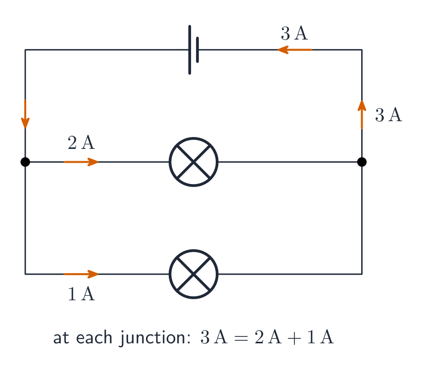
Kirchhoff's junction rule 基尔霍夫电流定律 (charge conservation): the total current into any junction equals the total current out. Together with the loop rule, it lets you solve any multi-loop circuit for its unknown currents.
Current divides at a junction: what flows in equals what flows out Vocabulary · 어휘 Train · 연습하기English 한국어 Kirchhoff's junction rule/ˈkɜːkhɒfs ˈdʒʌŋkʃn ruːl/ 키르히호프의 접점 법칙 11.8
RC Circuits
Syllabus
EnglishLearning Objective 11.8.A: Describe the equivalent capacitance of multiple capacitors.
- 11.8.A.1 A collection of capacitors in a circuit may be analyzed as though it were a single capacitor with an equivalent capacitance $C_{\text{eq}}$.
- 11.8.A.1.i The inverse of the equivalent capacitance of a set of capacitors connected in series is equal to the sum of the inverses of the individual capacitances.
- Equation: $\dfrac{1}{C_{\text{eq},s}} = \sum_i \dfrac{1}{C_i}$
- 11.8.A.1.ii The equivalent capacitance of a set of capacitors in series is less than the capacitance of the smallest capacitor.
- 11.8.A.1.iii The equivalent capacitance of a set of capacitors in parallel is the sum of the individual capacitances.
- Equation: $C_{\text{eq},p} = \sum_i C_i$
- 11.8.A.1.i The inverse of the equivalent capacitance of a set of capacitors connected in series is equal to the sum of the inverses of the individual capacitances.
- 11.8.A.2 As a result of conservation of charge, each of the capacitors in series must have the same magnitude of charge on each plate.
Learning Objective 11.8.B: Describe the behavior of a circuit containing combinations of resistors and capacitors.
- 11.8.B.1 The time constant $\tau$ is a significant feature of an RC circuit.
- 11.8.B.1.i The time constant of an RC circuit is a measure of how quickly the capacitor will charge or discharge and is defined as $\tau = R_{\text{eq}} C_{\text{eq}}$.
- 11.8.B.1.ii For a charging capacitor, the time constant represents the time required for the capacitor's charge to increase from zero to approximately 63 percent of its final asymptotic value.
- 11.8.B.1.iii For a discharging capacitor, the time constant represents the time required for the capacitor's charge to decrease from fully charged to approximately 37 percent of its initial value.
- 11.8.B.2 The potential difference across a capacitor and the current in the branch of the circuit containing the capacitor each change over time as the capacitor charges and discharges, but both will reach a steady state after a long time interval.
- 11.8.B.2.i Immediately after being placed in a circuit, an uncharged capacitor acts like a wire, and charge can easily flow to or from the plates of the capacitor.
- 11.8.B.2.ii As a capacitor charges, changes to the potential difference across the capacitor affect the charge on the plates of the capacitor, the current circuit branch in which the capacitor is located, and the electric potential energy stored in the capacitor.
- 11.8.B.2.iii The potential difference across a capacitor, the current in the circuit branch in which the capacitor is located, and the electric potential energy stored in the capacitor all change with respect to time and asymptotically approach steady state conditions.
- 11.8.B.2.iv After a long time, a charging capacitor approaches a state of being fully charged, reaching a maximum potential difference at which there is zero current in the circuit branch in which the capacitor is located.
- 11.8.B.2.v Immediately after a charged capacitor begins discharging, the amount of charge on the capacitor plates and the energy stored in the capacitor begin to decrease.
- 11.8.B.2.vi As a capacitor discharges, the amount of charge on the capacitor, the potential difference across the capacitor, and the current in the circuit branch in which the capacitor is located all decrease until a steady state is reached.
- 11.8.B.2.vii After either charging or discharging for times much greater than the time constant, the capacitor and the relevant circuit branch may be modeled using steady-state conditions.
Boundary statement: Descriptions of charging/discharging RC circuits in AP Physics 2 are limited to qualitative descriptions and representations. While students should be able to mathematically describe initial and final states of RC circuits, students are not expected to mathematically model these behaviors with respect to time.
한국어학습 목표 11.8.A: 여러 콘덴서의 등가 정전용량을 설명하십시오.
- 11.8.A.1 회로 내 콘덴서의 집합은 등가 정전용량 $C_{\text{eq}}$을 가진 단일 콘덴서로 처리하여 분석할 수 있습니다.
- 11.8.A.1.i 직렬로 연결된 콘덴서 집합의 등가 정전용량의 역수는 개별 정전용량의 역수의 합과 같습니다.
- 식: $\dfrac{1}{C_{\text{eq},s}} = \sum_i \dfrac{1}{C_i}$
- 11.8.A.1.ii 직렬로 연결된 콘덴서 집합의 등가 정전용량은 가장 작은 콘덴서의 정전용량보다 작습니다.
- 11.8.A.1.iii 병렬로 연결된 콘덴서 집합의 등가 정전용량은 개별 정전용량의 합과 같습니다.
- 식: $C_{\text{eq},p} = \sum_i C_i$
- 11.8.A.1.i 직렬로 연결된 콘덴서 집합의 등가 정전용량의 역수는 개별 정전용량의 역수의 합과 같습니다.
- 11.8.A.2电荷守恒의 결과, 직렬로 연결된 각 콘덴서의 각 극판에는 동일한 크기의 전하가 존재해야 합니다.
학습 목표 11.8.B: 저항기와 콘덴서의 조합이 포함된 회로의 거동을 설명하십시오.
- 11.8.B.1 시간 상수 $\tau$은 RC 회로의 중요한 특징입니다.
- 11.8.B.1.i RC 회로의 시간 상수는 콘덴서가 충전되거나 방전되는 속도를 나타내는 지표이며, $\tau = R_{\text{eq}} C_{\text{eq}}$로 정의됩니다.
- 11.8.B.1.ii 충전되는 콘덴서에서 시간 상수는 콘덴서의 전하량이 0에서 최종 점근값의 약 63%까지 증가하는 데 필요한 시간을 의미한다.
- 11.8.B.1.iii 방전되는 콘덴서에서 시간 상수는 콘덴서가 완전히 충전된 상태에서 초기 값의 약 37%까지 감소하는 데 필요한 시간을 의미한다.
- 11.8.B.2 축전기 양단의 전위차와 축전기가 포함된 회로 가지의 전류는 축전기가 충전되고 방전됨에 따라 시간에 따라 변화하지만, 긴 시간 간격이 지난 후에는 모두 안정 상태에 도달합니다.
- 11.8.B.2.i 회로에 즉시 연결된 순간, 미충전된 콘덴서는 전선과 같이 동작하여 콘덴서 극판 간을 전하가 쉽게 흐를 수 있게 한다.
- 11.8.B.2.ii 콘덴서가 충전됨에 따라 콘덴서 양단의 전위차 변화는 콘덴서 극판의 전하량, 콘덴서가 위치한 회로 가지 branch의 전류, 그리고 콘덴서에 저장된 전기potential 에너지에 영향을 미친다.
- 11.8.B.2.iii 콘덴서 양단의 전위차, 콘덴서가 위치한 회로 가지의 전류, 그리고 콘덴서에 저장된 전기potential 에너지는 모두 시간에 따라 변하며 점근적으로 정상 상태(steady state) 조건에 도달한다.
- 11.8.B.2.iv 긴 시간이 경과하면, 충전되는 콘덴서는 완전 충전 상태에 근접하며, 이 최대 전위차에서는 콘덴서가 위치한 회로 가지에 전류가 0이 된다.
- 11.8.B.2.v 충전된 콘덴서가 방전을 시작하는 즉시, 콘덴서 극판의 전하량과 콘덴서에 저장된 에너지는 감소하기 시작한다.
- 11.8.B.2.vi 콘덴서가 방전됨에 따라 콘덴서의 전하량, 콘덴서 양단의 전위차, 그리고 콘덴서가 위치한 회로 가지의 전류는 모두 정상 상태가 도달할 때까지 감소한다.
- 11.8.B.2.vii 충전 또는 방전이 시간 상수보다 훨씬 긴 시간이 경과한 후, 콘덴서와 관련 회로 가지는 정상 상태 조건을 사용하여 모델링될 수 있다.
*경계 문구: AP Physics 2에서의 RC 회로의 충전/방전 설명은 정성적 기술 및 표현으로 제한됩니다. 학생들은 RC 회로의 초기 및 최종 상태를 수학적으로 기술할 수 있어야 하지만, 이러한 거동을 시간에 대해 수학적으로 모델링할 것으로 기대하지 않습니다.
Source: College Board AP Course and Exam Description · 출처: College Board AP Course and Exam Description
Charging a capacitor (RC) An RC circuit RC电路 contains a resistor and a capacitor. When charging, the capacitor's voltage rises and the current falls, both exponentially, over a characteristic time $\tau=RC$. Key limits: at the first instant the uncharged capacitor acts like a plain wire (maximum current); after a long time it is fully charged and blocks current (acts like a break).
The charge on a capacitor decays exponentially as it discharges Worked example. For $R=10\ \text{k}\Omega$ and $C=100\ \mu\text{F}$, the time constant is $\tau=RC=(10\times10^{3})(100\times10^{-6})=1.0\ \text{s}$. After one time constant the capacitor reaches about $63\%$ of the supply voltage; after about $5\tau$ it is essentially fully charged.
Vocabulary · 어휘 Train · 연습하기English 한국어 RC circuit/ˌɑː ˈsiː ˈsɜːkɪt/ RC 회로 11.8
Exam tips
- In series the current is the same throughout; in parallel the voltage is the same across each branch — never mix these up.
- Combine resistors: series add; parallel $1/R_{\text{eq}}=\sum 1/R_i$ (the total is less than the smallest).
- Apply Kirchhoff's rules: junction (current in = current out, charge conserved) and loop (voltages sum to zero, energy conserved).
- Pick the power form that fits your knowns: $P=IV=I^2R=V^2/R$.
- An ammeter goes in series (ideal: zero resistance); a voltmeter goes in parallel (ideal: infinite resistance). A real meter slightly disturbs the circuit it measures.
- A bulb is brighter when it dissipates more power – in series the biggest resistance ($I^2R$) glows brightest; in parallel the smallest ($V^2/R$) does.
- In an RC circuit the capacitor acts like a plain wire the instant it starts charging and like a break once fully charged.
- 11.1.A.1 Current is the rate at which charge passes through a cross-sectional area of a wire.
-
12
Magnetism and Electromagnetism
Watch lesson · 수업 보기12.1
Magnetic Fields · 자기장
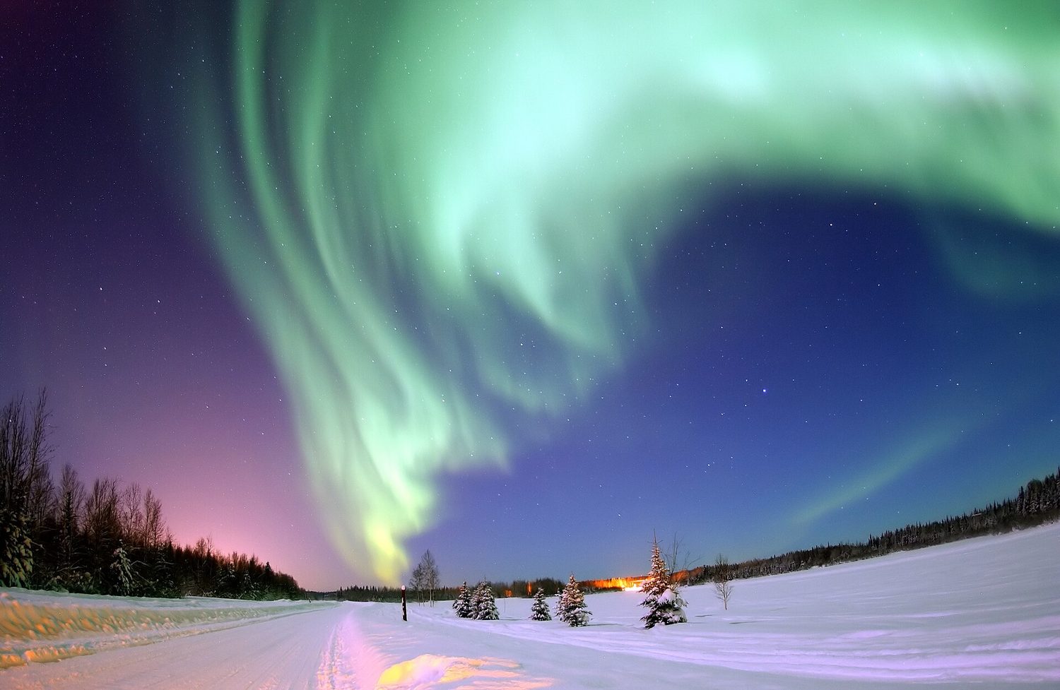
Syllabus
Learning Objective Essential Knowledge 12.1.A
Describe the properties of a magnetic field.- 12.1.A.1 A magnetic field is a vector field that can be used to determine the magnetic force exerted on moving electric charges, electric currents, or magnetic materials.
- 12.1.A.1.i Magnetic fields can be produced by magnetic dipoles or combinations of dipoles, but never by monopoles.
- 12.1.A.1.ii Magnetic dipoles have north and south polarity.
- 12.1.A.2 A magnetic field is a vector quantity and can be represented using vector field maps.
- 12.1.A.2.i Magnetic field lines form closed loops.
- 12.1.A.2.ii Magnetic fields in a bar magnet form closed loops, with the external magnetic field pointing away from one end (defined as the north pole) and returning to the other end (defined as the south pole).
12.1.B
Describe the magnetic behavior of a material as a result of the configuration of magnetic dipoles in the material.- 12.1.B.1 Magnetic dipoles result from the circular or rotational motion of electric charges. In magnetic materials, this can be the motion of electrons.
- 12.1.B.1.i Permanent magnetism and induced magnetism are system properties that both result from the alignment of magnetic dipoles within a system.
- 12.1.B.1.ii No magnetic north pole is ever found in isolation from a south pole. For example, if a bar magnet is broken in half, both halves are magnetic dipoles.
- 12.1.B.1.iii Magnetic poles of the same polarity will repel; magnetic poles of opposite polarity will attract.
- 12.1.B.1.iv The magnitude of the magnetic field from a magnetic dipole decreases with increasing distance from the dipole.
- 12.1.B.2 A magnetic dipole, such as a magnetic compass, placed in a magnetic field will tend to align with the magnetic field.
- 12.1.B.3 A material's composition influences its magnetic behavior in the presence of an external magnetic field.
- 12.1.B.3.i Ferromagnetic materials such as iron, nickel, and cobalt can be permanently magnetized by an external field that causes the alignment of magnetic domains or atomic magnetic dipoles.
- 12.1.B.3.ii Paramagnetic materials such as aluminum, titanium, and magnesium interact weakly with an external magnetic field, in that the magnetic dipoles of the material do not remain aligned after the external field is removed.
- 12.1.B.3.iii All materials have the property of diamagnetism, in that their electronic structure creates a usually weak alignment of the dipole moments of the material opposite the external magnetic field.
- 12.1.B4 Earth's magnetic field may be approximated as a magnetic dipole.
12.1.C
Describe the magnetic permeability of a material.- 12.1.C.1 Magnetic permeability is a measurement of the amount of magnetization in a material in response to an external magnetic field.
- 12.1.C.2 Free space has a constant value of magnetic permeability, known as the vacuum permeability $\mu_0$, that appears in equations representing physical relationships.
- 12.1.C.3 The permeability of matter has values different from that of free space and arises from the matter's composition and arrangement. It is not a constant for a material and varies based on many factors, including temperature, orientation, and strength of the external field.
Source: College Board AP Course and Exam Description · 출처: College Board AP Course and Exam Description
EnglishThe magnetic field around a current Different materials respond very differently to a magnetic field, and the course names three. Ferromagnetic 铁磁性 materials (iron, nickel, cobalt) have dipoles that align strongly and stay aligned, so they can be permanent magnets. Paramagnetic 顺磁性 materials (aluminium, titanium) align only weakly and do not stay aligned. Diamagnetic 抗磁性 materials - in fact all materials have some diamagnetism - align weakly opposite the field. This behaviour comes from a material property, the permeability 磁导率: free space has a fixed permeability of free space $\mu_0$, while the permeability of matter differs from it and is not even constant for a given material.
A magnetic field 磁场 $\vec{B}$ surrounds magnets and moving charges. Field lines run from a magnet's north pole to its south pole outside the magnet, and denser lines mean a stronger field. Magnetic poles always come in pairs – cutting a magnet in half makes two smaller magnets, never an isolated pole.
한국어전류 주변의 자기장 오로라: 태양에서 온带电 입자가 지구의 자기장에 의해 극지로 유도되어 대기 중 입자와 충돌하며 빛을 낸다 서로 다른 물질들은 자기장에 매우 다르게 반응하며, 본 과정에서는 세 가지를 다룬다. 자성체(ferromagnetic) 물질(철, 니켈, 코발트)은 쌍극자가 강하게 정렬되고 유지되므로 영구 자석이 될 수 있다. 상자성体(paramagnetic) 물질(알루미늄, 티타늄)은 약하게 정렬되고 유지되지 않는다. 반자성体(diamagnetic) 물질-사실 모든 물질은 약간의 반자성을 가진다-은 자기장과 반대 방향으로 약하게 정렬된다. 이 현상은 물질의 성질인 **투자기도(permeability)**에서 비롯된다: 진공은 고정된 진공 투자기도 $\mu_0$를 가지며, 물질의 투자기도는 이와 다르며 특정 물질에서도 일정하지 않을 수 있다.
자기장 $\vec{B}$은 자석과 이동 전하 주변을 둘러싼다. 자기장 선은 자석 외부에서 북극에서 남극으로 흐르며, 선이 밀집할수록 장이 강함을 의미한다. 자기극은 항상 쌍으로 존재한다-자석을 반으로 잘라내면 두 개의 작은 자석이 생기고, 단일 극은 절대 생성되지 않는다.
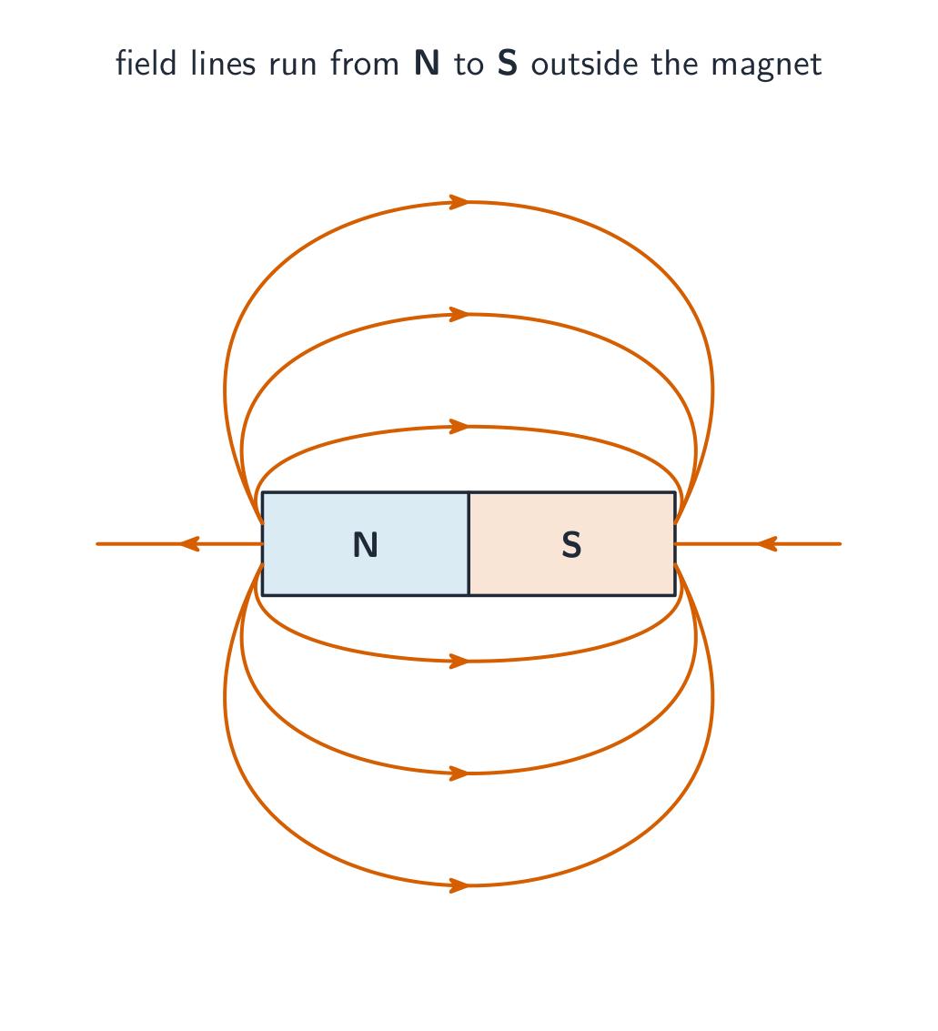
바 Magnet 외부에서 N에서 S로 흐르는 자기장 선, 장이 강한 곳일수록 밀집됨 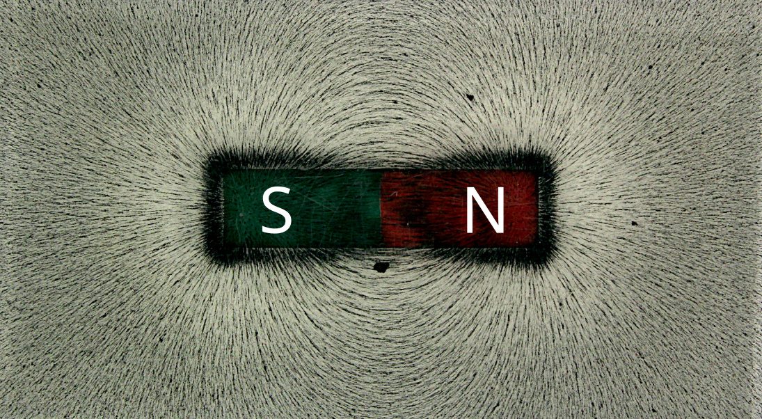
철가루가 자기장 선을 따라 정렬되어 바 Magnet의 보이지 않는 자기장 선을 시각적으로 나타냄 Explore · 탐색하기See a magnet's field lines · 자석의 자기력선 보기
Magnetic field lines run from the north pole to the south pole outside the magnet. Where the lines crowd together the field is strongest. · 자기장의 힘선은 자석 외부에서 북극에서 남극으로 향합니다. 힘선이 밀집한 곳일수록 자기장이最强합니다.
Vocabulary · 어휘 Train · 연습하기English 한국어 Ferromagnetic/ˌferəməɡˈnetɪk/ 강자성 Paramagnetic/ˌpærəməɡˈnetɪk/ 자화성 Diamagnetic/ˌdaɪəməɡˈnetɪk/ 반자성 permeability/ˌpɜːməˈbɪlɪti/ 자율률 magnetic field/mæɡˈnetɪk fiːld/ 자기장 12.2
Magnetism and Moving Charges · 자기학 및 이동 전하
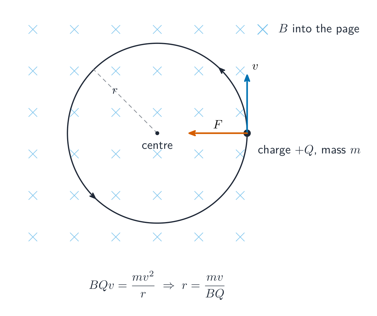
Syllabus
EnglishLearning Objective 12.2.A: Describe the magnetic field produced by moving charged objects.
- 12.2.A.1 A single moving charged object produces a magnetic field.
- 12.2.A.1.i The magnetic field at a particular point produced by a moving charged object depends on the object's velocity and the distance between the point and the object.
- 12.2.A.1.ii At a point in space, the direction of the magnetic field produced by a moving charged object is perpendicular to both the velocity of the object and the position vector from the object to that point in space and can be determined using the right-hand rule.
- 12.2.A.1.iii The magnitude of the magnetic field is a maximum when the velocity vector and the position vector from the object to that point in space are perpendicular.
Learning Objective 12.2.B: Describe the force exerted on moving charged objects by a magnetic field.
- 12.2.B.1 Magnetic forces describe interactions between moving charged objects.
- 12.2.B.2 A magnetic field may exert a force on a charged object moving in that field.
- 12.2.B.2.i The magnitude of the force exerted by a magnetic field on a moving charged object is proportional to the magnitude of the charge, the magnitude of the charged object's velocity, and the magnitude of the magnetic field and also depends on the angle between the velocity and magnetic field vectors.
- Equation: $F_B = qvB\sin\theta$
- 12.2.B.2.ii The direction of the force exerted by a magnetic field on a moving charged object is perpendicular to both the direction of the magnetic field and the velocity of the charge, as defined by the right-hand rule.
- 12.2.B.2.i The magnitude of the force exerted by a magnetic field on a moving charged object is proportional to the magnitude of the charge, the magnitude of the charged object's velocity, and the magnitude of the magnetic field and also depends on the angle between the velocity and magnetic field vectors.
- 12.2.B.3 In a region containing both a magnetic field and an electric field, a moving charged object will experience independent forces from each field.
- 12.2.B.4 The Hall effect describes the potential difference created in a conductor by an external magnetic field that has a component perpendicular to the direction of charges moving in the conductor.
Boundary statement: Quantitative treatment of the magnitude of the magnetic force exerted by a magnetic field on a moving charge is limited to angles of 0, 90, and 180 degrees between the velocity and the magnetic field. Qualitative analysis of other angles is permitted.
한국어학습 목표 12.2.A: 이동하는 전하를 띤 물체가 생성하는 자기장을 설명하시오.
- 12.2.A.1 단일 이동 전하 물체는 자기장을 생성한다.
- 12.2.A.1.i 특정 지점에서 이동 전하 물체에 의해 생성된 자기장은 해당 물체의 속도와 그 지점과 물체 사이의 거리에 의존한다.
- 12.2.A.1.ii 공간상 한 점에서 이동 전하 물체에 의해 생성되는 자기장의 방향은 물체의 속도와 물체로부터 해당 지점까지의 위치 벡터 모두와 수직이며, 오른손 법칙을 사용하여 결정할 수 있다.
- 12.2.A.1.iii 자기장의 크기는 물체의 속도 벡터와 해당 지점까지의 위치 벡터가 서로 수직일 때 최대가 된다.
학습 목표 12.2.B: 자기장이 이동 전하 물체에 가하는 힘에 대해 설명하시오.
- 12.2.B.1 자기력은 이동 전하 물체 간의 상호작용을 서술한다.
- 12.2.B.2 자기장은 해당 장 내에서 이동하는 전하 물체에 힘을 가할 수 있다.
- 12.2.B.2.i 자기장에 의한 이동 전하 물체에 가해지는 힘의 크기는 전하량, 물체의 속도 크기, 자기장 크기에 비례하며, 또한 속도 벡터와 자기장 벡터 사이의 각도에도 의존한다.
- 식: $F_B = qvB\sin\theta$
- 12.2.B.2.ii 자기장에 의한 이동 전하 물체에 가해지는 힘의 방향은 자기장 방향과 전하의 속도 방향 모두와 수직이며, 이는 오른손 법칙으로 정의된다.
- 12.2.B.2.i 자기장에 의한 이동 전하 물체에 가해지는 힘의 크기는 전하량, 물체의 속도 크기, 자기장 크기에 비례하며, 또한 속도 벡터와 자기장 벡터 사이의 각도에도 의존한다.
- 12.2.B.3 자기장과 전기장이 공존하는 영역에서는 이동 전하 물체가 각 장으로부터 독립적인 힘을 받는다.
- 12.2.B.4 홀 효과(Hall effect)는 도체 내로 이동하는 전하의 방향과 수직 성분을 가진 외부 자기장에 의해 도체에 생기는 전위차를 서술한다.
경계 문구: 자기장이 이동 전하에 가하는 자기력의 크기에 대한 정량적 처리는 속도와 자기장 사이의 각도가 0도, 90도, 180도인 경우에만 제한된다. 기타 각도에 대한 정성적 분석은 허용된다.
Source: College Board AP Course and Exam Description · 출처: College Board AP Course and Exam Description
EnglishA moving charge in a magnetic field A charge moving through a magnetic field feels a magnetic force 磁力:
$$F=qvB\sin\theta,$$where $\theta$ is the angle between the velocity and the field. The force is perpendicular to both $\vec{v}$ and $\vec{B}$ (use the right-hand rule), so it changes direction but not speed – a charge moving perpendicular to a uniform field travels in a circle. A stationary charge, or one moving parallel to the field, feels no magnetic force.Worked example. A proton ($q=1.6\times10^{-19}\ \text{C}$, $m=1.67\times10^{-27}\ \text{kg}$) enters a $0.50\ \text{T}$ field at $2.0\times10^{5}\ \text{m/s}$, at right angles to the field. The magnetic force is
$$F=qvB=1.6\times10^{-19}\times2.0\times10^{5}\times0.50=1.6\times10^{-14}\ \text{N}.$$This force is the centripetal force, so it bends the proton into a circle of radius$$r=\frac{mv}{qB}=\frac{1.67\times10^{-27}\times2.0\times10^{5}}{1.6\times10^{-19}\times0.50}=4.2\times10^{-3}\ \text{m}.$$Setting $qvB=\dfrac{mv^2}{r}$ and cancelling gives that neat $r=mv/(qB)$ – the principle behind mass spectrometers.한국어자기장 속을 이동하는 전하 자하 자기장 내에서 이동할 때 자기력을 받습니다:
$$F=qvB\sin\theta,$$여기서 $\theta$는 속도와 장 사이의 각도입니다. 힘은 $\vec{v}$과 $\vec{B}$(오른손 법칙 사용) 모두에 수직이므로 방향만 변경하고 속도는 변화하지 않습니다 – 균일한 자기장에 수직으로 이동하는 하전 입자는 원을 그립니다. 정지해 있거나 자기장 방향으로 이동하는 하전 입자는 자기력을 받지 않습니다.하전 입자가 자기장을 가로질러 이동하며 원형 궤적을 그립니다 해설 예제. 양성자($q=1.6\times10^{-19}\ \text{C}$, $m=1.67\times10^{-27}\ \text{kg}$)가 $0.50\ \text{T}$ 자기장 내에 $2.0\times10^{5}\ \text{m/s}$ 속도로 장과 수직으로 진입합니다. 여기에 작용하는 자기력은
$$F=qvB=1.6\times10^{-19}\times2.0\times10^{5}\times0.50=1.6\times10^{-14}\ \text{N}.$$이 힘은 approcentripetal force(원심력)이므로 양성자를 반지름의 원으로 휘게 만듭니다:$$r=\frac{mv}{qB}=\frac{1.67\times10^{-27}\times2.0\times10^{5}}{1.6\times10^{-19}\times0.50}=4.2\times10^{-3}\ \text{m}.$$$qvB=\dfrac{mv^2}{r}$를 대입하고 소거하면 깔끔한 $r=mv/(qB)$ 식이 도출됩니다 – 질량 분광기의 원리입니다.Vocabulary · 어휘 Train · 연습하기English 한국어 magnetic force/mæɡˈnetɪk fɔːs/ 자기력 12.3
Magnetism and Current-Carrying Wires · 자석과 전류가 흐르는 선
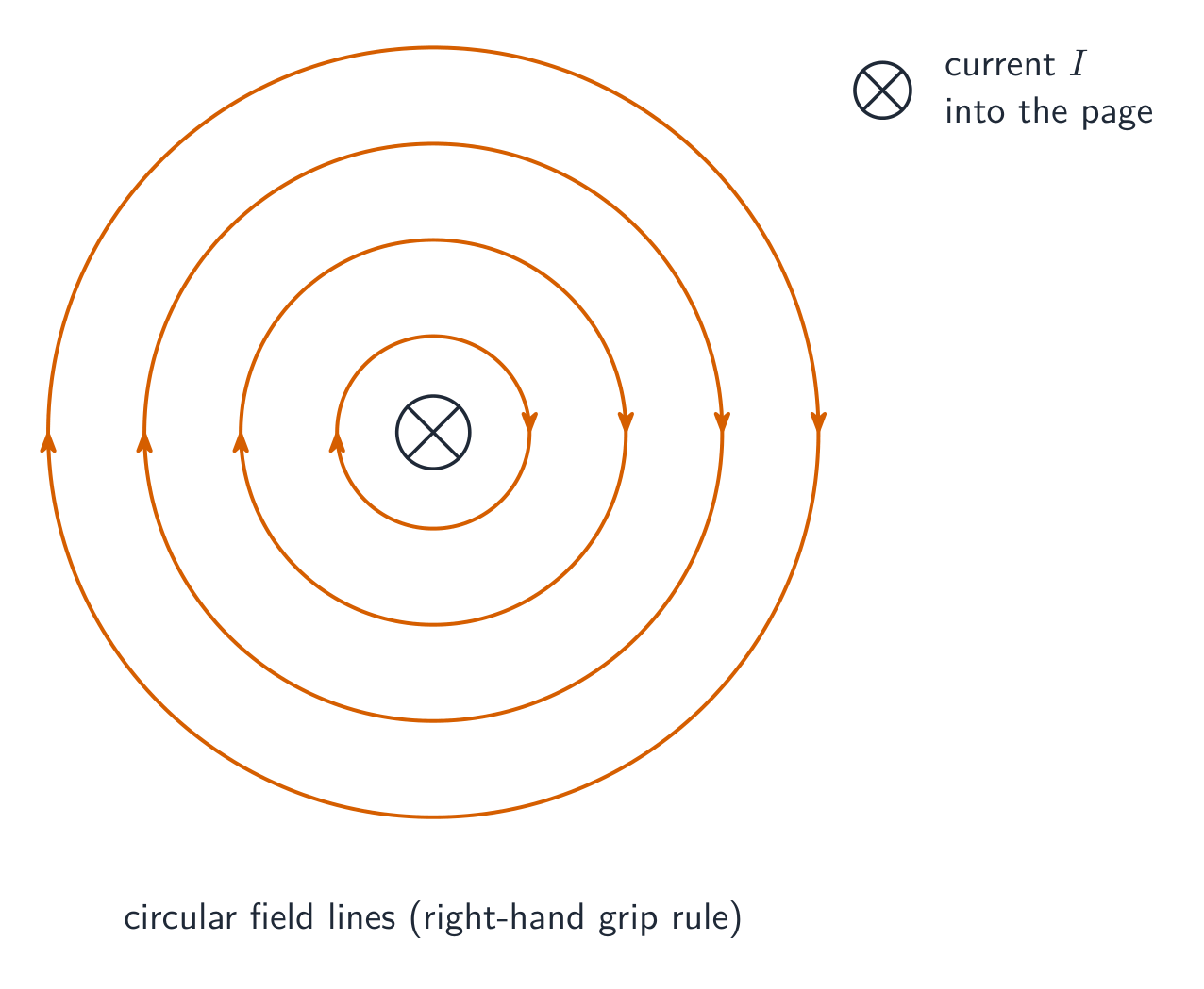
Syllabus
EnglishLearning Objective 12.3.A: Describe the magnetic field produced by a current-carrying wire.
- 12.3.A.1 A current-carrying wire produces a magnetic field.
- 12.3.A.1.i The magnetic field vectors around a long, straight, current-carrying wire are tangent to concentric circles centered on that wire. The field has no component toward, away from, or parallel to the long, straight, current-carrying wire.
- 12.3.A.1.ii At a point in space, the magnitude of the magnetic field due to a long, straight, current-carrying wire is proportional to the magnitude of the current in the wire and inversely proportional to the perpendicular distance from the central axis of the wire to the point.
- Equation: $B = \dfrac{\mu_0}{2\pi}\dfrac{I}{r}$
- 12.3.A.1.iii The direction of the magnetic field created by a current-carrying wire is determined with the right-hand rule.
- 12.3.A.1.iv The direction of the magnetic field at the center of a current-carrying loop is directed along the axis of the loop and can be found using the right-hand rule.
- 12.3.A.1.v The magnetic field at a location near two or more current-carrying wires can be determined using vector addition principles.
Learning Objective 12.3.B: Describe the force exerted on a current-carrying wire by a magnetic field.
- 12.3.B.1 A magnetic field may exert a force on a current-carrying wire.
- 12.3.B.1.i The magnitude of the force exerted by a magnetic field on a current-carrying wire is proportional to the current, the length of the portion of the wire within the magnetic field, and the magnitude of the magnetic field, and also depends on the angle between the direction of the current in the wire and the direction of the magnetic field.
- Equation: $F_B = I\ell B\sin\theta$
- 12.3.B.1.ii The direction of the force exerted by the magnetic field on a current-carrying wire is determined by the right-hand rule.
- 12.3.B.1.i The magnitude of the force exerted by a magnetic field on a current-carrying wire is proportional to the current, the length of the portion of the wire within the magnetic field, and the magnitude of the magnetic field, and also depends on the angle between the direction of the current in the wire and the direction of the magnetic field.
한국어학습 목표 12.3.A: 전류가 흐르는 선이 생성하는 자기장을 설명하시오.
- 12.3.A.1 전류가 흐르는 선은 자기장을 생성한다.
- 12.3.A.1.i 길고 직선적인 전류 도선 주변의 자기장 벡터들은 해당 도선을 중심으로 하는 동심 원에 접한다. 이 장은 길고 직선적인 전류 도선을 향하거나, 그 반대로 향하거나, 또는 평행한 성분을 가지지 않는다.
- 12.3.A.1.ii 공간상 한 점에서의 길고 직선적인 전류 도선에 의한 자기장의 크기는 도선 내 전류의 크기에 비례하고, 도선의 중심 축으로부터 해당 지점까지의 수직 거리에 반비례한다.
- 식: $B = \dfrac{\mu_0}{2\pi}\dfrac{I}{r}$
- 12.3.A.1.iii 전류 도선이 생성하는 자기장의 방향은 오른손 법칙으로 결정된다.
- 12.3.A.1.iv 전류 루프의 중심에서의 자기장 방향은 루프의 축을 따라 향하며, 오른손 법칙을 사용하여 찾을 수 있다.
- 12.3.A.1.v 두 개 이상의 전류 도선 근처의 지점에서의 자기장은 벡터 합성의 원리를 사용하여 결정할 수 있다.
학습 목표 12.3.B: 자기장이 전류가 흐르는 선에 가하는 힘에 대해 설명하시오.
- 12.3.B.1 자기장은 전류가 흐르는 선에 힘을 가할 수 있다.
- 12.3.B.1.i 자기장에 의한 전류 도선에 가해지는 힘의 크기는 전류, 자기장 내에 있는 도선의 길이, 그리고 자기장 크기에 비례하며, 또한 도선 내 전류 방향과 자기장 방향 사이의 각도에도 의존한다.
- 식: $F_B = I\ell B\sin\theta$
- 12.3.B.1.ii 자기장에 의한 전류 도선에 가해지는 힘의 방향은 오른손 법칙으로 결정된다.
- 12.3.B.1.i 자기장에 의한 전류 도선에 가해지는 힘의 크기는 전류, 자기장 내에 있는 도선의 길이, 그리고 자기장 크기에 비례하며, 또한 도선 내 전류 방향과 자기장 방향 사이의 각도에도 의존한다.
Source: College Board AP Course and Exam Description · 출처: College Board AP Course and Exam Description
EnglishBecause a current is moving charge, a magnetic field pushes on a current-carrying wire:
$$F=BIL\sin\theta.$$A current also creates its own magnetic field: circular field lines wrap around a straight wire (right-hand rule), and a coil (solenoid) makes a field like a bar magnet. This is how electromagnets and motors work.Worked example. A $0.30\ \text{m}$ length of wire carries $4.0\ \text{A}$ at right angles to a $0.20\ \text{T}$ field. The force on it is $F=BIL=0.20\times4.0\times0.30=0.24\ \text{N}$ – the push that turns a motor's coil.
한국어전류는 이동하는 전하이므로 자기장이 전류가 흐르는 선에 힘을 가합니다:
$$F=BIL\sin\theta.$$전류 또한 자체적인 자기장을 생성합니다: 직선 선 주위를 동심원形的인 자기장선이 감싸며(오른손 법칙), 코일(솔레노이드)은 막대자석과 유사한 자기장을 만듭니다. 이것이 전자기석과 모터의 작동 원리입니다.동심원形的인 자기장선이 직선 전류 선을 둘러쌉니다 해설 예제. 길이가 $0.30\ \text{m}$인 선에 전류 $4.0\ \text{A}$가 흐르며, 이는 $0.20\ \text{T}$ 자기장과 수직입니다. 이 선에 작용하는 힘은 $F=BIL=0.20\times4.0\times0.30=0.24\ \text{N}$ – 모터 코일을 회전시키는 힘입니다.
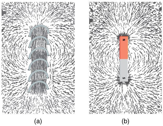
전류가 흐르는 코일(솔레노이드)은 막대자석과 동일한 모양의 자기장을 만듭니다 Explore · 탐색하기Find the force on a current in a field · 장 안에서의 전류에 작용하는 힘 찾기
A current in a magnetic field feels a force $F = BIL$, at right angles to both. Use the left-hand rule; reverse the current or field and the force flips. · 자기장 within 있는 전류는 두 방향 모두에 수직인 힘 $F = BIL$을 받습니다. 왼손 법칙을 사용하십시오; 전류나 장의 방향을 반대로 하면 힘의 방향도 바뀝니다.
12.4
Electromagnetic Induction and Faraday's Law · 전자기 유도 및 패러데이의 법칙
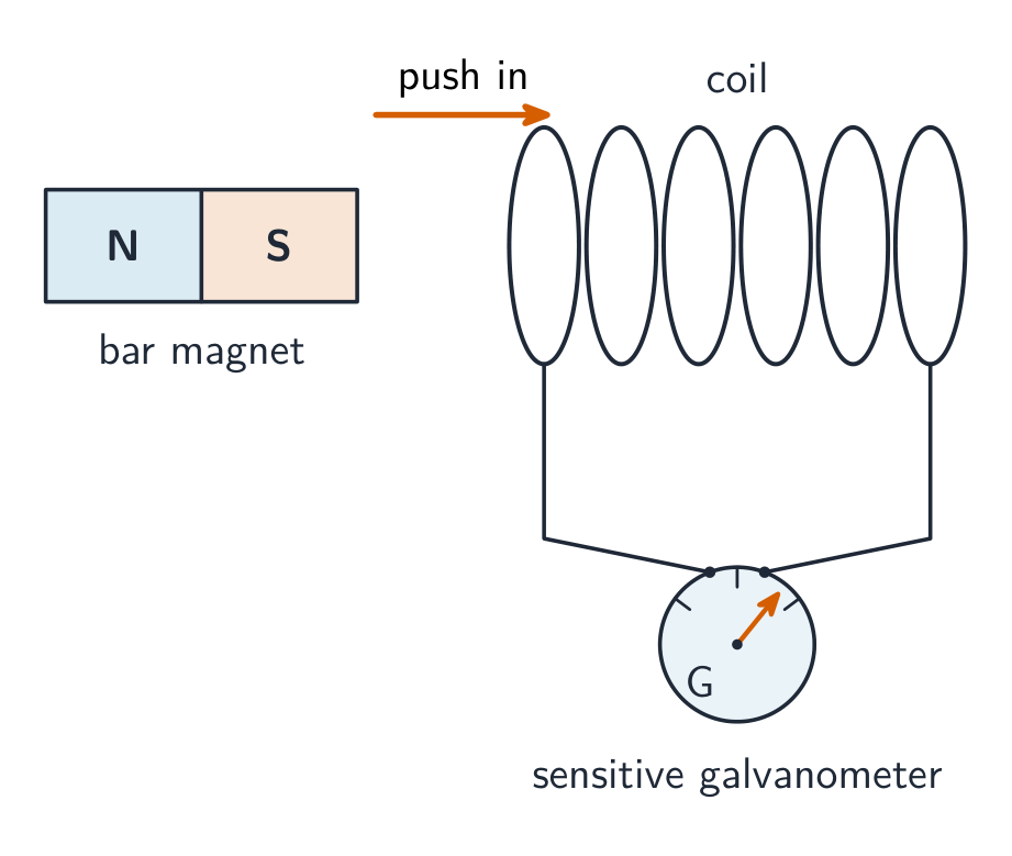
Syllabus
Learning Objective Essential Knowledge 12.4.A
Describe the induced electric potential difference resulting from a change in magnetic flux.- 12.4.A.1 Magnetic flux is a description of the amount of the component of a magnetic field that is perpendicular to a cross-sectional area.
- 12.4.A.2 Magnetic flux through a surface is proportional to the magnitude of the component of the magnetic field perpendicular to the surface and to the cross-sectional area of the surface.
- Equation: $\Phi_B = BA\cos\theta$
- 12.4.A.2.i The area vector is defined to be perpendicular to the plane of the surface and directed outward from a closed surface.
- 12.4.A.2.ii The sign of the magnetic flux indicates whether the magnetic field is parallel to or antiparallel to the area vector.
- 12.4.A.3 Faraday’s law describes the relationship between changing magnetic flux and the resulting induced emf in a system.
- Equation: $|\mathcal{E}| = \left|\dfrac{\Delta\Phi_B}{\Delta t}\right|$
- 12.4.A.4 Lenz’s law is used to determine the direction of an induced emf resulting from a changing magnetic flux.
- Equation: $\mathcal{E} = -\dfrac{\Delta\Phi_B}{\Delta t} = -\dfrac{\Delta(BA\cos\theta)}{\Delta t}$
- 12.4.A.4.i An induced emf generates a current that creates a magnetic field that opposes the change in magnetic flux.
- 12.4.A.4.ii The right-hand rule is used to determine the relationships between current, emf, and magnetic flux.
- 12.4.A.5 A common example of electromagnetic induction is a conducting rod on conducting rails in a region with a uniform magnetic field.
- Derived equation: $\mathcal{E} = B\ell v$
Source: College Board AP Course and Exam Description · 출처: College Board AP Course and Exam Description
EnglishElectromagnetic induction A changing magnetic field through a loop drives a current – electromagnetic induction 电磁感应. The magnetic flux 磁通量 $\Phi=BA\cos\theta$ measures how much field passes through the loop. Faraday's law 法拉第定律 gives the induced emf:
$$\varepsilon=-\frac{\Delta\Phi}{\Delta t}.$$The flux changes if the field, the area, or the loop's orientation changes. Lenz's law 楞次定律 (the minus sign) says the induced current flows so as to oppose the change that caused it – the basis of generators.Worked example. The magnetic flux through a single loop drops from $0.020\ \text{Wb}$ to $0.008\ \text{Wb}$ in $0.030\ \text{s}$. The average induced emf is
$$\varepsilon=\left|\frac{\Delta\Phi}{\Delta t}\right|=\frac{0.020-0.008}{0.030}=0.40\ \text{V}.$$A coil of $N$ turns would give $N$ times this – which is why generators and transformers use many-turn coils.한국어전자기유도 루프를 통과하는 변화하는 자기장은 전류를 유도합니다 – 전자기 유도. 자기 플럭스 $\Phi=BA\cos\theta$는 루프를 통과하는 장의 양을 측정합니다. 패러데이의 법칙은 유도된 기전력(emf)을 다음과 같이 줍니다:
$$\varepsilon=-\frac{\Delta\Phi}{\Delta t}.$$장, 면적, 또는 루프의 방향이 변하면 플럭스가 변화합니다. 렌츠의 법칙(마이너스 부호)은 유도 전류가 이를 유발한 변화를 저항하도록 흐른다고 합니다 – 발전기의 기초입니다.자석을 코일에 넣으면 유도된 e.m.f.가 전류를 흐르게 합니다 해설 예제. 단일 루프를 통과하는 자기 플럭스가 $0.020\ \text{Wb}$에서 $0.008\ \text{Wb}$로 $0.030\ \text{s}$ 동안 감소했습니다. 평균 유도 기전력은
$$\varepsilon=\left|\frac{\Delta\Phi}{\Delta t}\right|=\frac{0.020-0.008}{0.030}=0.40\ \text{V}.$$$N$회 코일은 이 값의 $N$배가 됩니다 – 이것이 발전기와 변압기에 다중 회 코일을 사용하는 이유입니다.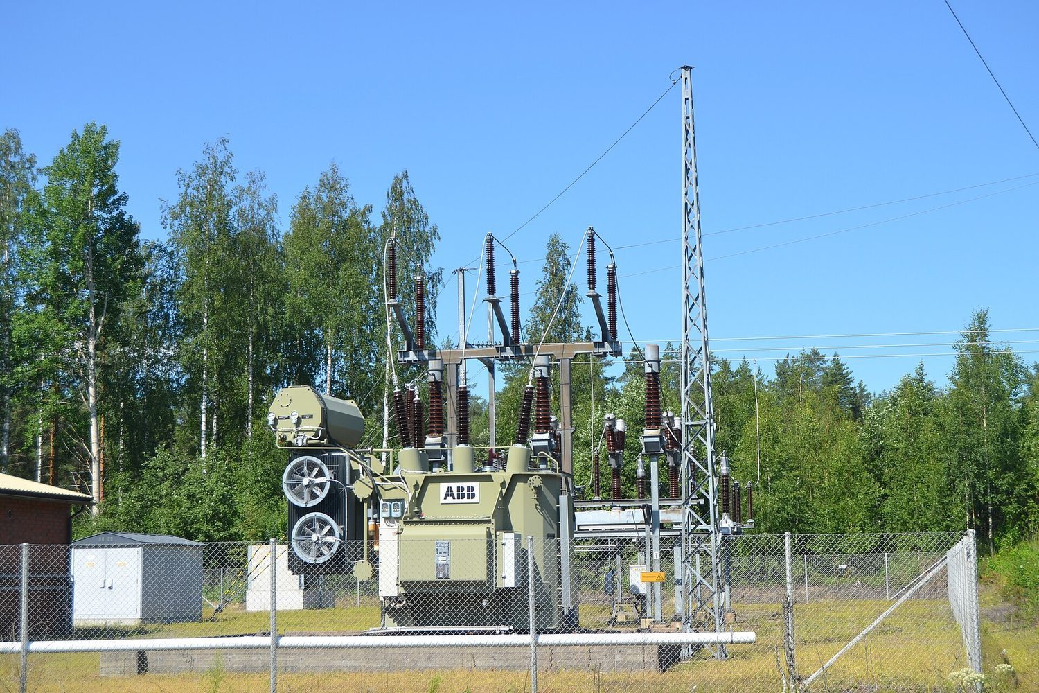
송전소 변압기: 코일의 변화하는 자기 플럭스가 전력망을 구동하는 전압을 유도합니다 Explore · 탐색하기Induce a voltage by moving a magnet · 자석을 움직여 전압 유도하기
Faraday's law: a changing magnetic flux through a coil induces a voltage. Move the magnet faster and the induced EMF grows; Lenz's law sets its direction to oppose the change. · 패러데이의 법칙: 코일을 통과하는 자기 흐름의 변화는 전압을 유도합니다. 자석을 빠르게 움직이면 유도 EMF가 커집니다. 렌츠의 법칙은 이 변화를 opposing 하는 방향으로 유도 전압의 방향을 정합니다.
Vocabulary · 어휘 Train · 연습하기English 한국어 electromagnetic induction/ɪˌlektrəʊməɡˈnetɪk ɪnˈdʌkʃn/ 전자기 유도 magnetic flux/mæɡˈnetɪk flʌks/ 자기 플럭스 Faraday's law/ˈfærədeɪz lɔː/ 패러데이의 법칙 Lenz's law/ˈlentsɪz lɔː/ 렌츠의 법칙 12.4
Exam tips · 시험 팁
English- The magnetic force $F=qvB\sin\theta$ is perpendicular to the velocity, so it changes direction (a circle) but not speed; a stationary charge or one moving along the field feels no force.
- Use $F=BIL$ for the force on a current-carrying wire (the motor effect).
- A current creates a magnetic field (circles around a wire; a solenoid acts like a bar magnet).
- Induction needs a changing flux $\Phi=BA$ — a stationary magnet in a coil induces nothing.
- Faraday: $\varepsilon=\Delta\Phi/\Delta t$ (times $N$ turns); Lenz: the induced current opposes the change (energy conservation).
한국어- 자기력 $F=qvB\sin\theta$은 속도에 수직이므로 방향(원)만 바꾸고 속도는 일정하며, 정지하거나 장 와 평행하게 이동하는 전하에는 힘이 없습니다.
- 전류가 흐르는 선에作用于하는 힘에 $F=BIL$를 사용합니다 (모터 효과).
- 전류는 자기장을 생성합니다 (선 주변 원형; 솔레노이드는 막대자석처럼 작용함).
- 유도에는 변화하는 플럭스 $\Phi=BA$가 필요합니다 – 코일 내 정지한 자석은何も 유도하지 않습니다.
- 패러데이: $\varepsilon=\Delta\Phi/\Delta t$ (× $N$ 권회 수); 렌츠: 유도 전류는 변화를 반대한다(에너지 보존).
- 12.1.A.1 A magnetic field is a vector field that can be used to determine the magnetic force exerted on moving electric charges, electric currents, or magnetic materials.
-
13
Geometric Optics
Watch lesson · 수업 보기13.1
Reflection
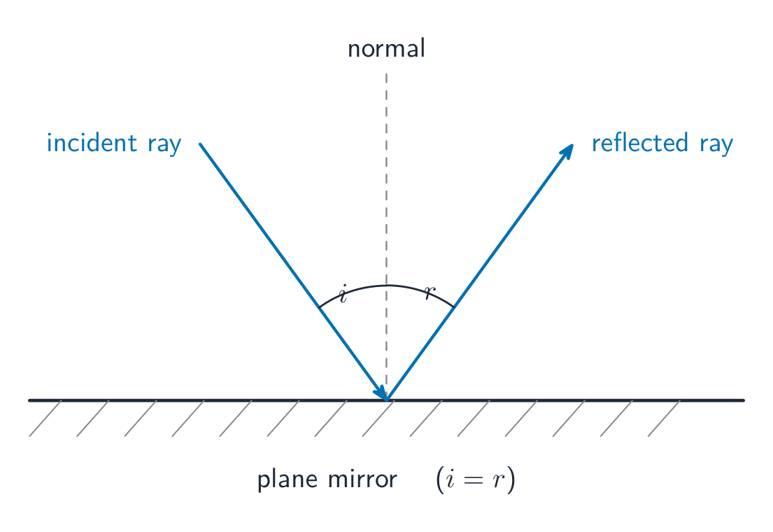
Syllabus
EnglishLearning Objective 13.1.A: Describe light as a ray.
- 13.1.A.1 A light ray is a straight line that is perpendicular to the wavefront of a light wave and points in the direction of travel of the wave.
- 13.1.A.1.i Light rays can be used to determine the behavior of light in geometric optics, where the wave nature of light can be neglected.
- 13.1.A.1.ii Rays are not sufficient to understand the spreading of light. In interference and diffraction, the wave nature of the light is important.
- 13.1.A.1.iii A laser is a common source of a single coherent, monochromatic beam of light that can be modeled as a ray. The wave nature of lasers will be considered in Unit 14.
- 13.1.A.2 Ray diagrams depict the path of light before and after an interaction with matter.
Learning Objective 13.1.B: Describe the reflection of light from a surface.
- 13.1.B.1 Light that is incident on a surface can be reflected.
- 13.1.B.2 The law of reflection states that the angle between the incident ray and the normal (the line perpendicular to the surface) is equal to the angle between the reflected ray and the normal.
- Equation: $\theta_i = \theta_r$
- 13.1.B.3 Diffuse reflection is the reflection of light from a rough surface and results in light reflected in many different directions, because the line normal to the surface varies over the area over which the light is incident.
- 13.1.B.4 Specular reflection is the reflection of light from a smooth surface and results in light uniformly reflected from the surface, because the line normal to the surface has an approximately constant direction over the area the light strikes.
한국어학습 목표 13.1.A: 빛을 광선(rays)으로 설명하라.
- 13.1.A.1 빛의 광선은 빛의 파면(wavefront)에 수직이며 파동의 진행 방향을 가리키는 직선이다.
- 13.1.A.1.i 빛의 파동적 성질을 무시할 수 있는 기하광학에서 빛의 거동을 파악하기 위해 광선을 사용할 수 있다.
- 13.1.A.1.ii 광선만으로는 빛의 퍼짐 현상을 이해하기에 충분하지 않다. 간섭과 회절에서는 빛의 파동적 성질이 중요하다.
- 13.1.A.1.iii 레이저는 단일 코어런트(코히런트), 단색 광선으로 모델링될 수 있는 일반적인 광원이다. 레이저의 파동적 성질은 14단원에서 다룬다.
- 13.1.A.2 광선도는 물질과의 상호작용 전후의 빛의 경로를 나타낸다.
학습 목표 13.1.B: 표면에서의 빛의 반사를 설명하라.
- 13.1.B.1 표면에 입사하는 빛은 반사될 수 있다.
- 13.1.B.2 반사의 법칙에 따르면 입사광선과 법선(표면에 수직인 선) 사이의 각도는 반사광선과 법선 사이의 각도와 같다.
- 식: $\theta_i = \theta_r$
- 13.1.B.3 난반사(diffuse reflection)는 거친 표면에서의 빛의 반사로, 빛이 입사하는 면적 전체에서 표면에 대한 법선의 방향이 달라지므로 빛이 다양한 방향으로 반사된다.
- 13.1.B.4 정반사(specular reflection)는 매끄러운 표면에서의 빛의 반사로, 빛이 닿는 면적 전반에 걸쳐 표면에 대한 법선의 방향이 대략 일정하므로 빛이 표면에서 균일하게 반사된다.
Source: College Board AP Course and Exam Description · 출처: College Board AP Course and Exam Description
Geometric optics 几何光学 treats light as straight-line rays. The law of reflection 反射定律: when light bounces off a surface, the angle of incidence 入射角 equals the angle of reflection 反射角, both measured from the normal (the line perpendicular to the surface). Smooth surfaces reflect a clear image; rough surfaces scatter the rays.
The law of reflection: the angle of incidence equals the angle of reflection Vocabulary · 어휘 Train · 연습하기English 한국어 Geometric optics/ˌdʒiːəʊˈmetrɪk ˈɒptɪks/ 기하 광학 law of reflection/lɔː ɒv rɪˈflekʃn/ 반사의 법칙 angle of incidence/ˈæŋɡl ɒv ˈɪnsɪdəns/ 입사각 angle of reflection/ˈæŋɡl ɒv rɪˈflekʃn/ 반사각 13.2
Images Formed by Mirrors
Syllabus
EnglishLearning Objective 13.2.A: Describe the image formed by a mirror.
- 13.2.A.1 Incident light rays parallel to the principal axis of a concave (converging) mirror will be reflected toward a common location, called the focal point.
- 13.2.A.2 Incident light rays parallel to the principal axis of a convex (diverging) mirror will be reflected such that they appear to have originated from a common location behind the mirror, called the focal point.
- 13.2.A.3 The focal point of a plane mirror is an infinite distance from the mirror.
- 13.2.A.4 The focal point of a spherical mirror may be approximated as a point located on the principal axis of the mirror halfway between the surface of the mirror and the center of the mirror's radius of curvature.
- 13.2.A.5 A real image is formed by a mirror when light rays emanating from a common point are reflected and then intersect at a common point.
- 13.2.A.6 A virtual image is formed by a mirror when reflected light rays diverge such that they appear to have originated from a common point.
- 13.2.A.7 The location of an image depends on the focal length of the mirror and the distance between the object and the surface of the mirror.
- Equation: $\dfrac{1}{s_i} + \dfrac{1}{s_o} = \dfrac{1}{f}$
- 13.2.A.7.i The locations of a mirror's focal point, an object near the mirror, and the image of the object formed by the mirror follow sign conventions that are used to determine those locations relative to the mirror itself.
- 13.2.A.7.ii The distance between the image formed and a plane mirror is equal to the distance between the object and the plane mirror.
- 13.2.A.8 The magnification of an image formed by a mirror is the ratio of the size of the image produced to the size of the object itself and depends on the locations of the object and image relative to the mirror.
- Equation: $|M| = \left| \dfrac{h_i}{h_o} \right| = \left| \dfrac{s_i}{s_o} \right|$
- 13.2.A.9 Ray diagrams can be used to determine the location, type, size, and orientation of images formed by mirrors.
- 13.2.A.9.i The three principal rays are typically used to find the images formed by mirrors. The principal rays are 1) the ray parallel to the principal axis, 2) the ray that reflects at the center of the mirror where the principal axis intersects the mirror, and 3) the ray that passes through the focal point of the mirror.
- 13.2.A.9.ii Images formed by a mirror can be upright or inverted, virtual or real, and reduced, enlarged, or the same size as the object.
Boundary statement: AP Physics 2 limits the study of mirrors to plane mirrors, convex spherical mirrors, and concave spherical mirrors.
한국어학습 목표 13.2.A: 거울에 의해 형성된 상을 설명하라.
- 13.2.A.1 오목(수렴) 거울의 주축에 평행한 입사광선은 초점(focal point)이라고 불리는 공통 지점으로 반사된다.
- 13.2.A.2 볼록(발산) 거울의 주축에 평행한 입사광선은 거울 뒤쪽의 초점이라고 불리는 공통 지점에서 시작된 것처럼 보이는 방향으로 반사된다.
- 13.2.A.3 평면거울의 초점은 거울로부터 무한대 거리에 위치한다.
- 13.2.A.4 구면거울의 초점은 거울 표면과 거울의 곡률 반경 중심 사이를 잇는 주축상에서 거울 표면으로부터 절반 떨어진 점으로 근사할 수 있다.
- 13.2.A.5 실제 상(real image)은 공통 지점에서 발산한 빛의 광선이 반사되어 다시 공통 지점에서 교차할 때 거울에 의해 형성된다.
- 13.2.A.6 가상의 상(virtual image)은 반사광선이 발산하여 공통 지점에서 시작된 것처럼 보이는 경우 거울에 의해 형성된다.
- 13.2.A.7 상의 위치는 거울의 초점 거리와 물체와 거울 표면 사이의 거리에 따라 결정된다.
- 식: $\dfrac{1}{s_i} + \dfrac{1}{s_o} = \dfrac{1}{f}$
- 13.2.A.7.i 거울의 초점, 거울 근처의 물체, 그리고 거울에 의해 형성된 물체의 상의 위치는 거울 자체에 대해 그 위치를 결정하기 위해 사용되는 부호 규약(sign convention)을 따른다.
- 13.2.A.7.ii 평면거울에 의해 형성된 상과 평면거울 사이의 거리는 물체와 평면거울 사이의 거리와 같다.
- 13.2.A.8 거울에 의해 형성된 상의 배율(magnification)은 생성된 상의 크기와 실제 물체의 크기의 비율이며, 물체와 상의 거울에 대한 상대적 위치에 따라 달라진다.
- 식: $|M| = \left| \dfrac{h_i}{h_o} \right| = \left| \dfrac{s_i}{s_o} \right|$
- 13.2.A.9 광선도를 사용하여 거울에 의해 형성된 상의 위치, 종류, 크기 및 방향을 알 수 있다.
- 13.2.A.9.i 거울에 의해 형성된 상을 찾기 위해 일반적으로 세 가지 주요 광선(principal rays)이 사용된다. 주요 광선은 1) 주축에 평행한 광선, 2) 주축이 거울과 만나는 지점에서 반사되는 광선, 3) 거울의 초점을 통과하는 광선이다.
- 13.2.A.9.ii 거울에 의해 형성된 상은 정립(upright)이거나 역立(inverted)일 수 있으며, 가상이거나 실제일 수 있고, 물체보다 작거나 크거나 동일한 크기가 될 수 있다.
경계문(boundary statement): AP 물리학 2에서는 거울에 대한 연구가 평면거울, 볼록 구면거울 및 오목 구면거울로 제한된다.
Source: College Board AP Course and Exam Description · 출처: College Board AP Course and Exam Description
A curved mirror focuses parallel rays at its focal point, a distance $f$ from the mirror. The mirror equation relates object and image distances:
$$\frac{1}{d_o}+\frac{1}{d_i}=\frac{1}{f},\qquad m=-\frac{d_i}{d_o}.$$A concave mirror 凹面镜 (converging) can form a real image 实像 (rays actually meet, projectable, inverted); a convex mirror 凸面镜 always forms a virtual image 虚像 (rays only appear to meet, upright, reduced). The magnification $m$ gives the image's size and orientation. Sign convention matters: a negative image distance means a virtual image behind the mirror or lens.Explore · 탐색하기Form an image with a curved mirror · 곡면 거울로 상 형성하기
A concave mirror reflects rays through its focus. The object's distance relative to the focal length decides whether the image is real or virtual, enlarged or reduced. · 오목 거울은 광선을 초점을 통과하게 반사합니다. 물체의 거리가 초점 거리에 따라 상이 실상인지 허상인지, 확대된 것인지 축소된지를 결정합니다.
Vocabulary · 어휘 Train · 연습하기English 한국어 concave mirror/kɒnˈkeɪv ˈmɪrə/ 오목 거울 real image/rɪəl ˈɪmɪdʒ/ 실상 convex mirror/kɒnˈveks ˈmɪrə/ 우거울 virtual image/ˈvɜːtʃuːəl ˈɪmɪdʒ/ 가상像 13.3
Refraction
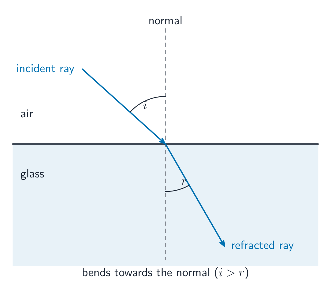
Syllabus
EnglishLearning Objective 13.3.A: Describe the refraction of light between two media.
- 13.3.A.1 Refraction is the change in direction of a light ray as the ray passes from one medium into another.
- 13.3.A.2 Refraction is a result of the speed of light changing when light enters a new medium.
- 13.3.A.3 The index of refraction of a given medium is inversely proportional to the speed of light in the medium.
- Equation: $n = \dfrac{c}{v}$
- 13.3.A.4 Snell's law relates the angles of incidence and refraction of a light ray passing from one medium into another to the indices of refraction of the two media.
- Equation: $n_1 \sin\theta_1 = n_2 \sin\theta_2$
- 13.3.A.4.i When a light ray travels from a medium with a higher index of refraction into a medium with a lower index of refraction, the ray refracts away from the normal.
- 13.3.A.4.ii When a light ray travels from a medium with a lower index of refraction into a medium with a higher index of refraction, the ray refracts toward the normal.
- 13.3.A.4.iii When a light ray is incident along the normal to a surface, the transmitted ray is not refracted.
- 13.3.A.5 Total internal reflection may occur when light passes from one medium into another medium with a lower index of refraction.
- 13.3.A.5.i Total internal reflection of light occurs beyond a critical angle of incidence.
- Derived equation: $\theta_{\text{critical}} = \sin^{-1}\left( \dfrac{n_2}{n_1} \right)$
- 13.3.A.5.ii For incident rays at the critical angle, the ray refracts at 90 degrees and travels along the surface of the material.
- 13.3.A.5.iii For incident rays beyond the critical angle, all light is reflected (no light is transmitted into the other medium).
- 13.3.A.5.i Total internal reflection of light occurs beyond a critical angle of incidence.
한국어학습 목표 13.3.A: 두 매질 사이의 빛의 굴절을 설명하라.
- 13.3.A.1 굴절은 빛의 광선이 한 매질에서 다른 매질로 이동하면서 방향이 바뀌는 현상이다.
- 13.3.A.2 굴절은 빛이 새로운 매질로 진입할 때 빛의 속도가 변하기 때문에 발생한다.
- 13.3.A.3 특정 매질의 굴절률은 해당 매질 내에서의 빛의 속도에 반비례한다.
- 식: $n = \dfrac{c}{v}$
- 13.3.A.4 스네লের 법칙(Snell's law)은 한 매질에서 다른 매질로 이동하는 빛의 광선에 대한 입사각과 굴절각이 두 매질의 굴절률과 어떻게 관련되는지를 나타낸다.
- 식: $n_1 \sin\theta_1 = n_2 \sin\theta_2$
- 13.3.A.4.i 빛의 광선이 굴절률이 높은 매질에서 굴절률이 낮은 매질로 이동할 때, 광선은 법선으로부터 멀어지는 방향으로 굴절된다.
- 13.3.A.4.ii 빛의 광선이 굴절률이 낮은 매질에서 굴절률이 높은 매질로 이동할 때, 광선은 법선 쪽으로 굴절된다.
- 13.3.A.4.iii 빛의 광선이 표면에 수직(법선 방향)으로 입사할 때 투과광선은 굴절되지 않는다.
- 13.3.A.5 빛이 굴절률이 낮은 매질로 진입할 때 전반사(total internal reflection)가 발생할 수 있다.
- 13.3.A.5.i 빛의 전반사는 입사각이 한계각(critical angle)을 초과할 때 발생한다.
- 파생 식: $\theta_{\text{critical}} = \sin^{-1}\left( \dfrac{n_2}{n_1} \right)$
- 13.3.A.5.ii 한계각에서의 입사광선은 90도로 굴절되어 매질의 표면을 따라 진행한다.
- 13.3.A.5.iii 한계각보다 큰 입사각에서는 모든 빛이 반사되며(다른 매질로 투과되는 빛은 없다).
- 13.3.A.5.i 빛의 전반사는 입사각이 한계각(critical angle)을 초과할 때 발생한다.
Source: College Board AP Course and Exam Description · 출처: College Board AP Course and Exam Description
Light bends when it passes between materials because its speed changes – refraction 折射. Each material has an index of refraction 折射率 $n=\dfrac{c}{v}$ (how much it slows light). Snell's law 斯涅尔定律:
$$n_1\sin\theta_1=n_2\sin\theta_2.$$Light entering a denser medium (larger $n$) bends toward the normal. Beyond a critical angle, light going to a less-dense medium reflects entirely – total internal reflection 全反射, used in fibre optics.Light refracts, bending towards the normal as it enters glass Worked example. A ray in air ($n_1=1.00$) strikes water ($n_2=1.33$) at $40^{\circ}$ to the normal. By Snell's law,
$$\sin\theta_2=\frac{n_1}{n_2}\sin\theta_1=\frac{1.00}{1.33}\sin 40^{\circ}=0.483\;\Rightarrow\;\theta_2=29^{\circ}.$$The ray bends toward the normal, as expected going into the denser medium.Worked example (critical angle). For light trying to leave glass ($n=1.50$) for air, total internal reflection begins at the critical angle $\theta_c$ where the refracted ray grazes the surface:
$$\sin\theta_c=\frac{1}{n}=\frac{1}{1.50}=0.667\;\Rightarrow\;\theta_c=42^{\circ}.$$Any ray hitting the inside surface more steeply than $42^{\circ}$ is trapped – the reason optical fibres carry light for kilometres.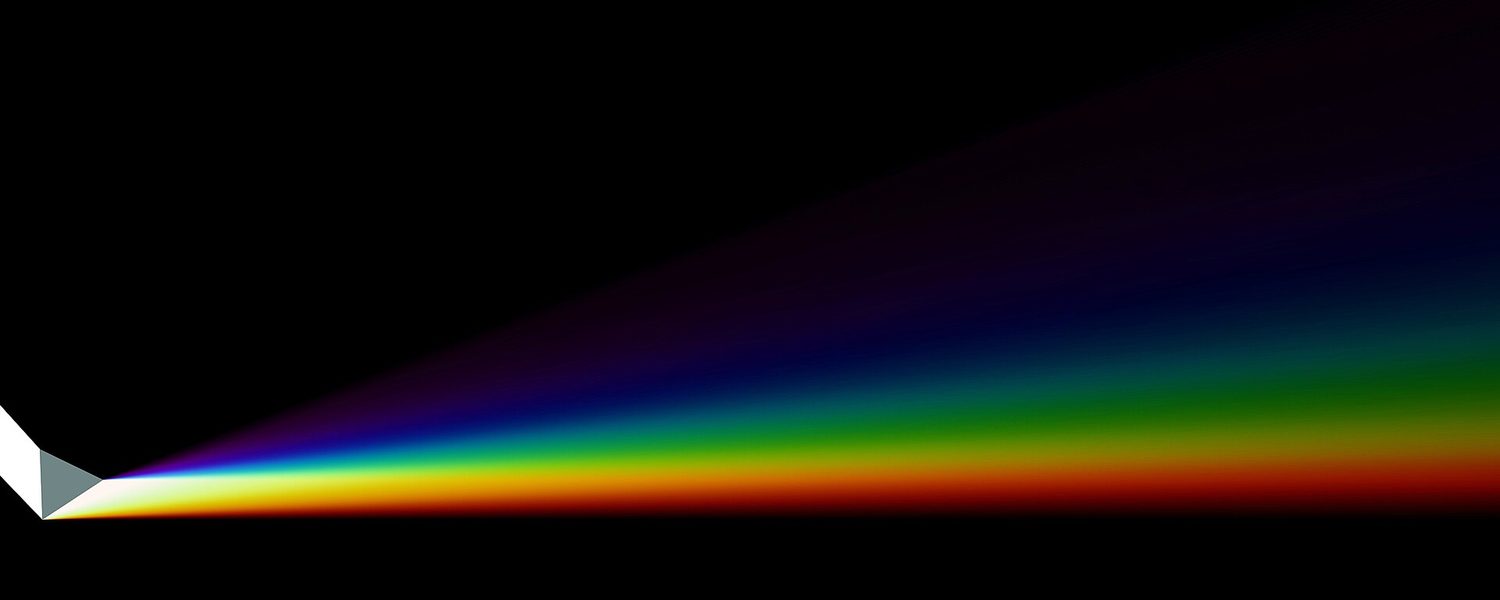
Refraction bends each colour by a different amount, so a prism spreads white light into a rainbow Explore · 탐색하기Bend light as it enters glass · 유리 안으로 들어가는 빛의 굴절
Light refracts (bends) when it changes speed between media, following Snell's law. The denser the medium, the more it bends toward the normal. · 빛이 매질을 따라 속도가 변할 때 굴절되어 꺾이며, 스넬의 법칙을 따릅니다. 매질이 밀할수록 빛은 법선에 더 가깝게 굽습니다.
Vocabulary · 어휘 Train · 연습하기English 한국어 refraction/rɪˈfrækʃn/ 굴절각 index of refraction/ˈɪndeks ɒv rɪˈfrækʃn/ 굴절률 Snell's law/snelz lɔː/ 스넬의 법칙 total internal reflection/ˈtəʊtl ɪnˈtɜːnl rɪˈflekʃn/ 전반사 13.4
Images Formed by Lenses
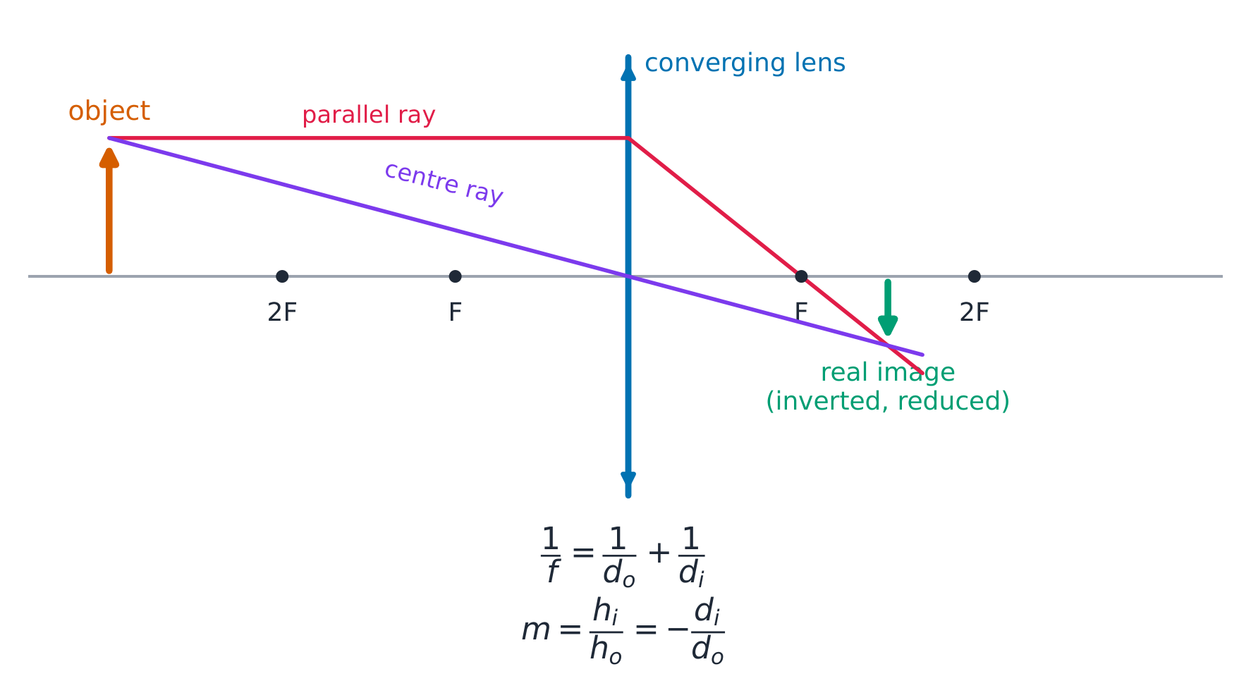
Syllabus
EnglishLearning Objective 13.4.A: Describe the image formed by a lens.
- 13.4.A.1 Incident light rays parallel to the principal axis of a thin convex (converging) lens will be refracted and converge toward a common location on the transmitted side of the lens, called the focal point.
- 13.4.A.2 Incident light rays parallel to the principal axis of a thin concave (diverging) lens will be refracted and diverge as if they originated from a focal point on the incident side of the lens.
- 13.4.A.3 A real image is formed by a lens when light rays originating from a common point are refracted such that they intersect at another common point.
- 13.4.A.4 A virtual image is formed by a lens when refracted light rays diverge such that they appear to have originated from a common point.
- 13.4.A.5 For a thin lens, the location of an image depends on the focal length of the lens and the distance between the object and the midline of the lens, as given by the thin-lens equation:
- Equation: $\dfrac{1}{s_i} + \dfrac{1}{s_o} = \dfrac{1}{f}$
- 13.4.A.5.i The locations of a lens's focal point, an object, and the image of the object formed by the lens follow sign conventions that are used to determine those locations relative to the lens itself.
- 13.4.A.5.ii Lenses have a focal point on both sides of the lens that depends on the shape of the respective side of the lens.
- 13.4.A.6 For a thin lens, the magnification of an image is the ratio of the size of the image produced to the size of the object itself and depends on the locations of the object and image relative to the lens.
- Equation: $|M| = \left| \dfrac{h_i}{h_o} \right| = \left| \dfrac{s_i}{s_o} \right|$
- 13.4.A.7 Ray diagrams can be used to determine the location, type, size, and orientation of images formed by lenses.
- 13.4.A.7.i The three principal rays are typically used to find the images formed by lenses. The principal rays are 1) the ray parallel to the principal axis, 2) the ray that passes through the center of the lens where the principal axis intersects the lens, and 3) the ray that passes through the focal point of the lens.
- 13.4.A.7.ii Images formed by a lens can be upright or inverted, virtual or real, and reduced, enlarged, or the same size as the object.
한국어학습 목표 13.4.A: 렌즈에 의해 형성된 이미지를 설명하시오.
- 13.4.A.1 얇은 볼록 렌즈(converging lens)의 주축(principal axis)과 평행한 입사광선은 굴절되어 렌즈의 투과측에서 공통 지점인 초점(focal point)으로 수렴한다.
- 13.4.A.2 얇은 오목 렌즈(diverging lens)의 주축과 평행한 입사광선은 굴절되어 마치 렌즈의 입사측에 있는 초점에서 기원한 것처럼 발산한다.
- 13.4.A.3 실상(real image)은 공통 지점에서 나오는 광선이 굴절되어 다시 다른 공통 지점에서 교차할 때 렌즈에 의해 형성된다.
- 13.4.A.4 가상(virtual image)은 굴절된 광선이 발산하여 마치 공통 지점에서 기원한 것처럼 보이는 경우 렌즈에 의해 형성된다.
- 13.4.A.5 얇은 렌즈에서 이미지의 위치는 렌즈의 초점 거리와 물체와 렌즈 중심선 사이의 거리에 따라 얇은 렌즈 방정식에 의해 결정된다:
- 식: $\dfrac{1}{s_i} + \dfrac{1}{s_o} = \dfrac{1}{f}$
- 13.4.A.5.i 렌즈의 초점, 물체 및 렌즈에 의해 형성된 물체의 이미지의 위치는 렌즈 자체에 대한 그 위치를 결정하는 데 사용되는 부호 규칙(sign conventions)을 따른다.
- 13.4.A.5.ii 렌즈는 렌즈의 각 면 모양에 따라 양쪽에 초점을 가진다.
- 13.4.A.6 얇은 렌즈에서 이미지의 확대율은 렌즈에 의해 생성된 이미지의 크기와 물체 자체의 크기 사이의 비율이며, 물체와 이미지의 렌즈에 대한 위치에 의존한다.
- 식: $|M| = \left| \dfrac{h_i}{h_o} \right| = \left| \dfrac{s_i}{s_o} \right|$
- 13.4.A.7 광선도(ray diagrams)를 사용하여 렌즈에 의해 형성된 이미지의 위치, 유형, 크기 및 방향을 결정할 수 있다.
- 13.4.A.7.i 렌즈에 의해 형성된 이미지를 찾기 위해 일반적으로 세 가지 주요 광선(main rays)을 사용한다. 주요 광선은 1) 주축과 평행한 광선, 2) 주축이 렌즈와 만나는 렌즈의 중심을 통과하는 광선, 3) 렌즈의 초점을 통과하는 광선이다.
- 13.4.A.7.ii 렌즈에 의해 형성된 이미지는 정립(upright) 또는 역立(inverted), 가상 또는 실상, 축소(reduced), 확대(enlarged) 또는 물체와 동일한 크기일 수 있다.
Source: College Board AP Course and Exam Description · 출처: College Board AP Course and Exam Description
A converging lens forms a real image A lens bends light through refraction. The thin-lens equation has the same form as the mirror equation:
$$\frac{1}{d_o}+\frac{1}{d_i}=\frac{1}{f},\qquad m=-\frac{d_i}{d_o}.$$A converging 会聚 (convex) lens can form a real, inverted image or, for a close object, a virtual, upright, enlarged image (a magnifying glass). A diverging 发散 (concave) lens always forms a virtual, upright, reduced image. Ray diagrams locate the image quickly using two easy rays: one parallel to the axis that bends to pass through the far focus, and one straight through the centre of the lens (undeviated).Two rays locate the image: parallel-then-focus, and straight through the centre 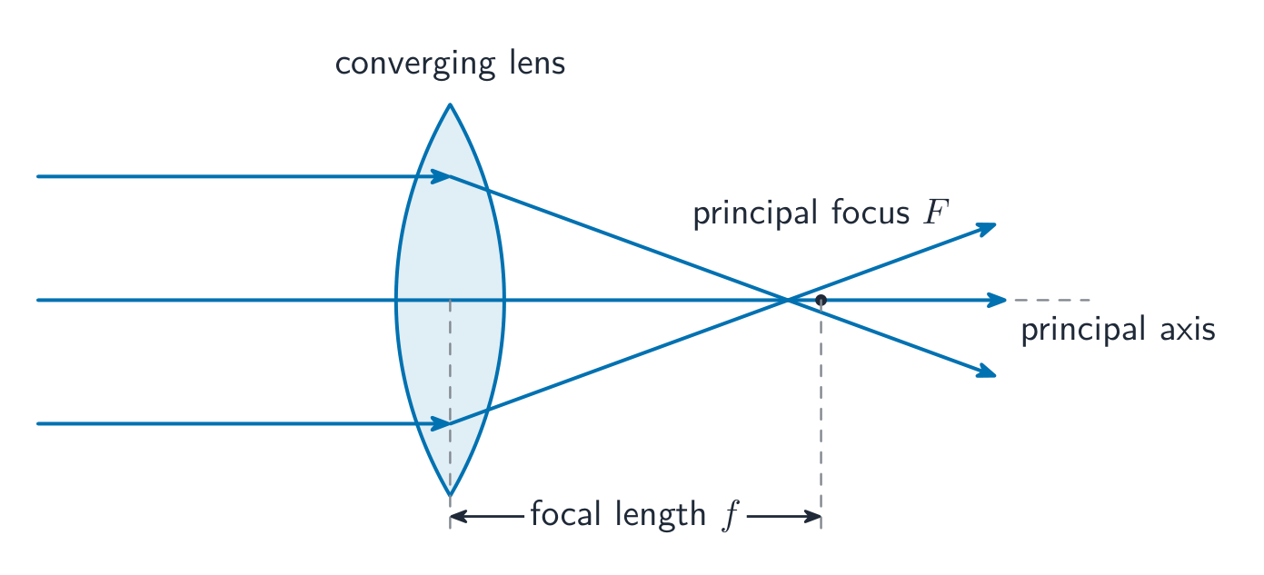
A converging lens brings parallel rays to its principal focus Worked example. An object sits $30\ \text{cm}$ from a converging lens of focal length $f=10\ \text{cm}$. Find the image. From the thin-lens equation,
$$\frac{1}{d_i}=\frac{1}{f}-\frac{1}{d_o}=\frac{1}{10}-\frac{1}{30}=\frac{2}{30}\;\Rightarrow\;d_i=15\ \text{cm},$$and the magnification is $m=-d_i/d_o=-15/30=-0.5$. The image is real (positive $d_i$), inverted (negative $m$), and half the object's size – just what a camera lens does.
A convex lens forms a real, inverted image of a distant scene, exactly as the ray diagram predicts Explore · 탐색하기Form an image with a converging lens · 발산 렌즈로 상 형성하기
A converging lens bends parallel rays to its focal point. Move the object and watch the image change from large and inverted to virtual and upright inside the focal length. · 발산 렌즈는 평행 광선을 초점으로 모읍니다. 물체를 움직이면 초점 거리 내부에서 상이 커지고 뒤집힌 것에서 작고 바로 선 가상상으로 변하는 것을 관찰할 수 있습니다.
Vocabulary · 어휘 Train · 연습하기English 한국어 converging/kənˈvɜːdʒɪŋ/ 수렴하는 diverging/daɪˈvɜːdʒɪŋ/ 발산하는 13.4
Exam tips
- Measure all angles from the normal, not the surface.
- Light entering a denser medium (larger $n$) bends toward the normal; use Snell's law $n_1\sin\theta_1=n_2\sin\theta_2$.
- Total internal reflection happens only going into a less dense medium, beyond the critical angle ($\sin\theta_c=1/n$).
- For mirrors and lenses use $\tfrac1{d_o}+\tfrac1{d_i}=\tfrac1f$ and $m=-d_i/d_o$: a positive $d_i$ is a real image, negative is virtual.
- $n=c/v$, so a bigger index means a slower speed of light in the material.
- 13.1.A.1 A light ray is a straight line that is perpendicular to the wavefront of a light wave and points in the direction of travel of the wave.
-
14
Waves, Sound, and Physical Optics
Watch lesson · 수업 보기14.1
Properties of Wave Pulses and Waves
Syllabus
Learning Objective Essential Knowledge 14.1.A
Describe the physical properties of waves and wave pulses.- 14.1.A.1 Waves transfer energy between two locations without transferring matter between those locations.
- 14.1.A.1.i A wave pulse is a single disturbance that transfers energy without transferring matter between two locations.
- 14.1.A.1.ii A wave is modeled as a continuous, periodic disturbance with well-defined wavelength and frequency.
- 14.1.A.2 Mechanical waves or wave pulses require a medium in which to propagate. Electromagnetic waves or wave pulses do not require a medium in which to propagate.
- 14.1.A.3 The speed at which a wave or wave pulse propagates through a medium depends on the type of wave and the properties of the medium.
- 14.1.A.3.i The speed of all electromagnetic waves in a vacuum is a universal physical constant, $c = 3.00 \times 10^{8}$ m/s.
- 14.1.A.3.ii The speed at which a wave pulse or wave propagates along a string is dependent upon the tension in the string, $F_T$, and the mass per length of the string.
- Equation: $v_{\text{string}} = \sqrt{\dfrac{F_T}{m/\ell}}$
- 14.1.A.3.iii In a given medium, the speed of sound waves increases with the temperature of the medium.
- 14.1.A.4 In a transverse wave, the direction of the disturbance is perpendicular to the direction of propagation of the wave.
- 14.1.A.5 In a longitudinal wave, the direction of the disturbance is parallel to the direction of propagation of the wave.
- 14.1.A.5.i Sound waves are modeled as mechanical longitudinal waves.
- 14.1.A.5.ii The regions of high and low pressure in a sound wave are called compressions and rarefactions, respectively.
- 14.1.A.6 Amplitude is the maximum displacement of a wave from its equilibrium position.
- 14.1.A.6.i The amplitude of a longitudinal pressure wave may be determined by the maximum increase or decrease in pressure from equilibrium pressure.
- 14.1.A.6.ii The loudness of a sound increases with increasing amplitude.
- 14.1.A.6.iii The energy carried by a wave increases with increasing amplitude.
Source: College Board AP Course and Exam Description · 출처: College Board AP Course and Exam Description
Ripple-tank interference: wave paths add constructively and destructively A wave 波 carries energy through a medium (or space) without carrying the matter along. A single disturbance is a pulse; a repeating one is a wave. Two types:
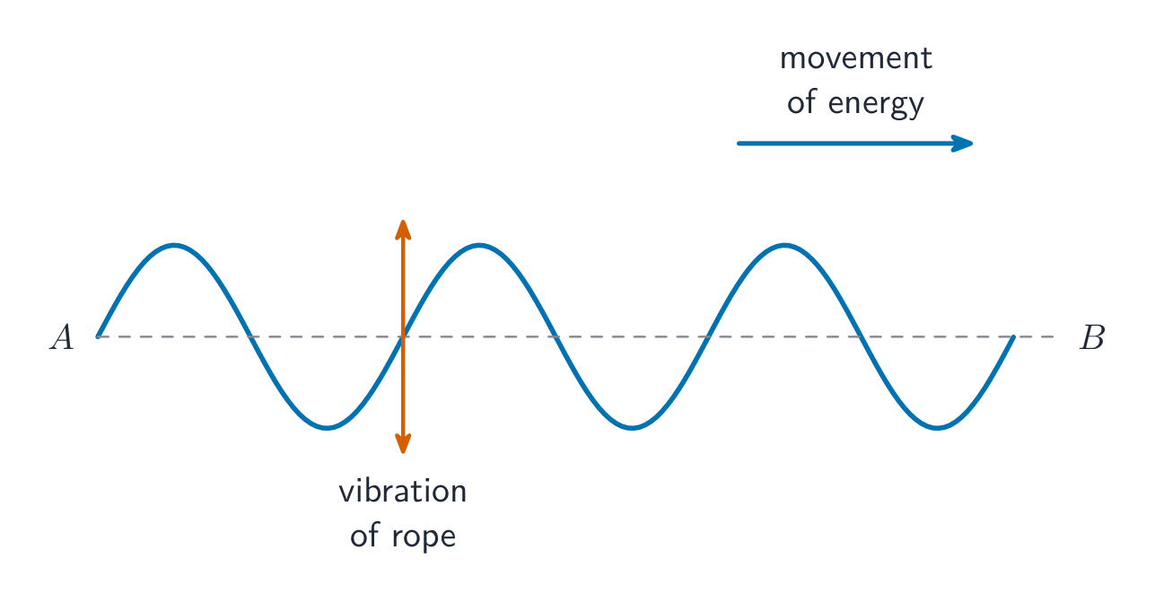
A transverse wave: the medium moves at right angles to the wave's travel - Transverse 横波: the medium moves perpendicular to the wave's travel (a wave on a rope, light).
- Longitudinal 纵波: the medium moves along the direction of travel (sound).
Vocabulary · 어휘 Train · 연습하기English 한국어 wave/weɪv/ 파동으로 treating 한다 Transverse/trænsˈvɜːs/ 횡파 Longitudinal/ˌlɒŋɡɪˈtjuːdɪnl/ Longitudinal 14.2
Periodic Waves
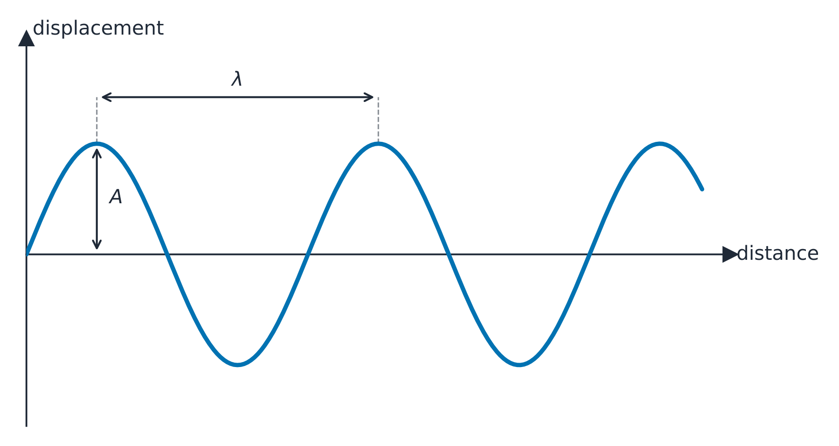
Syllabus
EnglishLearning Objective 14.2.A: Describe the physical properties of a periodic wave.
- 14.2.A.1 Periodic waves have regular repetitions that can be described using period and frequency.
- 14.2.A.1.i The period is the time for one complete oscillation of the wave.
- 14.2.A.1.ii The frequency is the rate at which the wave repeats.
- Equation: $T = \dfrac{1}{f}$
- 14.2.A.1.iii The amplitude of a wave is independent of the period and the frequency of that wave.
- 14.2.A.1.iv The energy of a wave increases with increasing frequency.
- 14.2.A.1.v The frequency of a sound wave is related to its pitch.
- 14.2.A.1.vi Wavelength is the distance between successive corresponding positions (such as peaks or troughs) on a wave.
- 14.2.A.2 A sinusoidal wave can be described by equations for the displacement from equilibrium at a specific location as a function of time. A wave can also be described by an equation for the displacement from equilibrium at a specific time as a function of position.
- Equation: $x(t) = A\cos(\omega t) = A\cos(2\pi f t)$
- Equation: $y(x) = A\cos\left(2\pi \dfrac{x}{\lambda}\right)$
- 14.2.A.3 For a periodic wave, the wavelength is proportional to the wave's speed and inversely proportional to the wave's frequency.
- Equation: $\lambda = \dfrac{v}{f}$
한국어학습 목표 14.2.A: 주기적 파동의 물리적 특성을 설명할 수 있다.
- 14.2.A.1 주기적 파동은 주기와 주파수를 사용하여 설명할 수 있는 일정한 반복 패턴을 가진다.
- 14.2.A.1.i 주기는 파동이 한 번의 완전한 진동을 하는 데 걸리는 시간이다.
- 14.2.A.1.ii 주파수는 파동이 반복되는 속도를 나타낸다.
- 식: $T = \dfrac{1}{f}$
- 14.2.A.1.iii 파동의 진폭은 해당 파동의 주기와 주파수에 독립적이다.
- 14.2.A.1.iv 파동의 에너지는 주파수가 증가함에 따라 커진다.
- 14.2.A.1.v 음파의 주파수는 소리의 높이에 관련된다.
- 14.2.A.1.vi 파장은 파동상에서 연속된 대응 위치(예: 봉우리와 골) 사이의 거리이다.
- 14.2.A.2 사인파는 특정 위치에서의 평형으로부터의 변위를 시간의 함수로 나타내는 식으로 설명할 수 있다. 또한 파동은 특정 시간에서의 평형으로부터의 변위를 위치의 함수로 나타내는 식으로도 설명할 수 있다.
- 식: $x(t) = A\cos(\omega t) = A\cos(2\pi f t)$
- 식: $y(x) = A\cos\left(2\pi \dfrac{x}{\lambda}\right)$
- 14.2.A.3 주기적 파동의 경우, 파장은 파동의 속도에 비례하고 주파수에 반비례한다.
- 식: $\lambda = \dfrac{v}{f}$
Source: College Board AP Course and Exam Description · 출처: College Board AP Course and Exam Description
Transverse vs longitudinal waves A repeating wave is described by:
A displacement-distance graph shows the amplitude and wavelength - wavelength 波长 $\lambda$ (distance between repeats),
- frequency 频率 $f$ (cycles per second) and period $T=1/f$,
- amplitude 振幅 $A$ (maximum displacement – related to energy),
- wave speed 波速 $v=f\lambda$, set by the medium, not the source.
Worked example. A musical note has frequency $340\ \text{Hz}$ and the speed of sound is $340\ \text{m/s}$. Its wavelength is $\lambda=v/f=340/340=1.0\ \text{m}$. If the same note travels into water (where sound moves at $\approx 1500\ \text{m/s}$) the frequency stays $340\ \text{Hz}$ but the wavelength stretches to $1500/340\approx 4.4\ \text{m}$ – the source sets the frequency, the medium sets the speed and hence the wavelength.
Explore · 탐색하기Send a periodic wave · 주파수 파동 보내기
A periodic wave carries energy without moving matter. Its speed $v=f\lambda$ links frequency and wavelength; raise the frequency and the wavelength shrinks. · 주파수 파동은 물질을 이동시키지 않고 에너지를 전달합니다. 이 파동의 속도 $v=f\lambda$는 주파수와 파장을 연결하며, 주파수를 높이면 파장은 짧아집니다.
Vocabulary · 어휘 Train · 연습하기English 한국어 wavelength/ˈweɪvleŋθ/ 파장 frequency/ˈfriːkwənsi/ 주파수 amplitude/ˈæmplɪtjuːd/ 진폭 wave speed/weɪv spiːd/ 파속 14.3
Boundary Behavior and Polarization
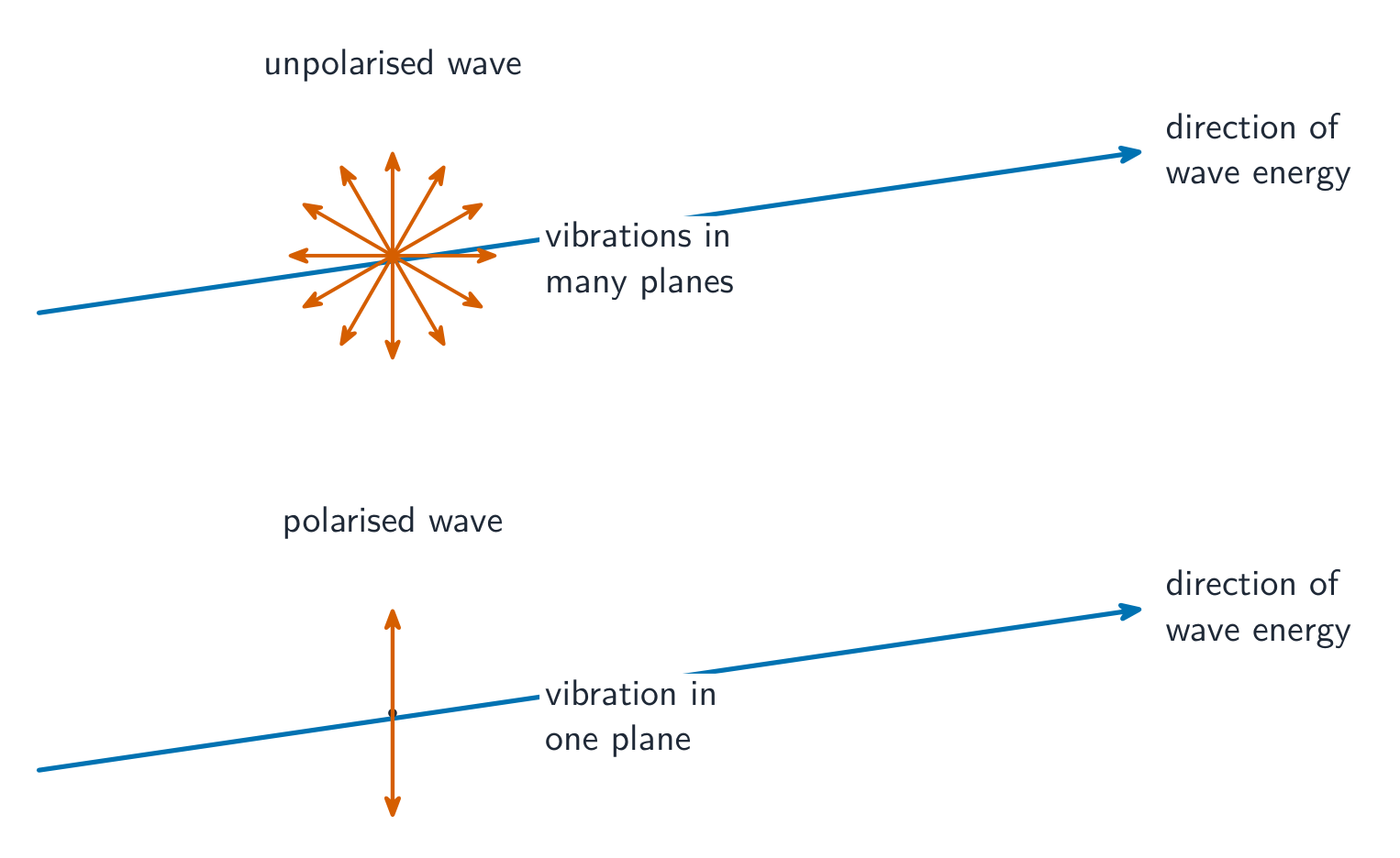
Syllabus
EnglishLearning Objective 14.3.A: Describe the interaction between a wave and a boundary.
- 14.3.A.1 A wave that travels from one medium to another can be transmitted or reflected, depending on the properties of the boundary separating the two media.
- 14.3.A.1.i A wave traveling from one medium to another (for example, a wave traveling between low-mass and high-mass strings) will result in reflected and transmitted waves.
- 14.3.A.1.ii A reflected wave is inverted if the transmitted wave travels into a medium in which the speed of the wave decreases.
- 14.3.A.1.iii A reflected wave is not inverted if the transmitted wave travels into a medium in which the speed of the wave increases.
- 14.3.A.1.iv The frequency of a wave does not change when it travels from one medium to another.
- 14.3.A.2 Transverse waves that are reflected from a surface, refracted through a medium, or pass through specific openings may be polarized.
- 14.3.A.2.i Transverse waves can be polarized and oscillate in a single plane.
- 14.3.A.2.ii Longitudinal waves cannot be polarized.
- 14.3.A.3 Polarization of a wave may result in a reduction of the wave's intensity.
- 14.3.A.3.i Intensity is a measure of the amount of power transferred per unit area.
- 14.3.A.3.ii The intensity of a wave is the average power per unit area over one period of the wave.
한국어학습 목표 14.3.A: 파동과 경계 사이의 상호작용을 서술하시오.
- 14.3.A.1 한 매질에서 다른 매질로 이동하는 파동은 두 매질을隔开하는 경계의 성질에 따라 투과되거나 반사될 수 있다.
- 14.3.A.1.i 한 매질에서 다른 매질로 이동하는 파동(예: 저질량 현과 고질량 현 사이를 이동하는 파동)은 반사파와 투과파를 발생시킨다.
- 14.3.A.1.ii 투과파가 파동의 속도가 감소하는 매질로 진입할 때, 반사파는 위상이 반전된다(거꾸로 진동한다).
- 14.3.A.1.iii 투과파가 파동의 속도가 증가하는 매질로 진입할 때, 반사파는 위상 반전이 일어나지 않는다.
- 14.3.A.1.iv 파동이 한 매질에서 다른 매질로 이동할 때 주파수는 변하지 않는다.
- 14.3.A.2 표면에서 반사되거나 매질을 통해 굴절되거나 특정 개구를 통과한 횡파는 편광될 수 있다.
- 14.3.A.2.i 횡파는 편광될 수 있으며 단일 평면 내에서 진동한다.
- 14.3.A.2.ii 종파는 편광될 수 없다.
- 14.3.A.3 파동의 편광은 파동의 세기 감소를 초래할 수 있다.
- 14.3.A.3.i 세기는 단위 면적당 전달되는 전력의 양을 측정하는 지표이다.
- 14.3.A.3.ii 파동의 세기는 파동의 한 주기에 걸친 단위 면적당 평균 전력이다.
Source: College Board AP Course and Exam Description · 출처: College Board AP Course and Exam Description
Total internal reflection At a boundary a wave partly reflects and partly transmits. Reflecting off a denser medium inverts the wave; off a less-dense medium it does not. Polarization 偏振 applies to transverse waves only: a polarizer passes just one direction of oscillation, which is why polarized sunglasses cut glare.
The effect of a polarizer is measured through intensity 强度 - the average power a wave delivers per unit area over one period, in $\text{W m}^{-2}$. Because a polarizer removes the components of the oscillation that are not aligned with it, it reduces the wave's intensity: unpolarized light passing a single ideal polarizer drops to half its intensity, and a second polarizer at an angle cuts it further. Intensity also falls with distance from a source, since the same power spreads over a larger area.
Unpolarised waves vibrate in many planes; a polarised wave vibrates in one Vocabulary · 어휘 Train · 연습하기English 한국어 Polarization/ˌpəʊləraɪˈzeɪʃn/ 편광 intensity/ɪnˈtensɪti/ 강도 14.4
Electromagnetic Waves
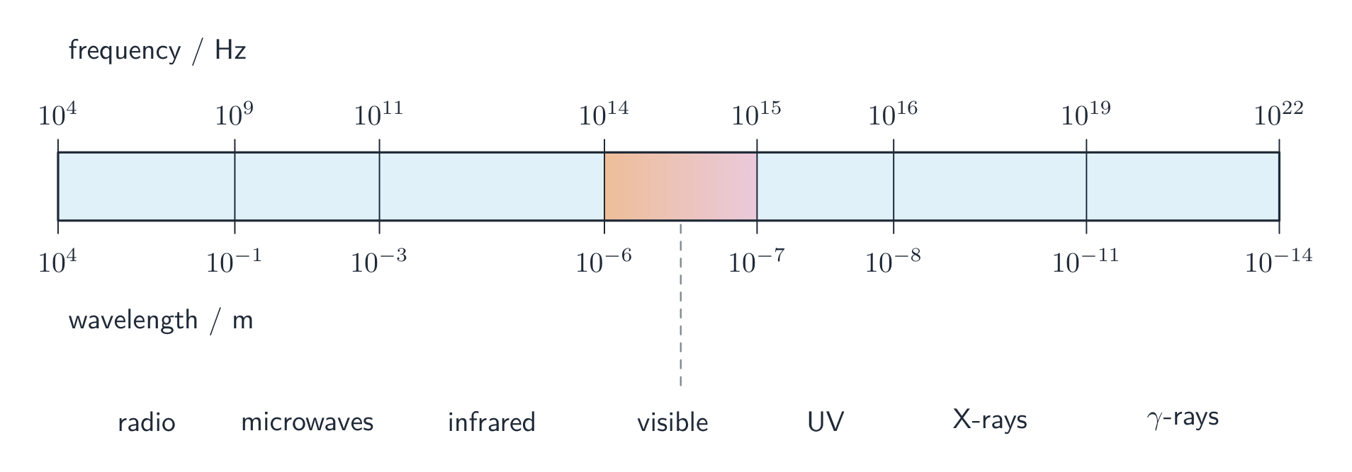
Syllabus
EnglishLearning Objective 14.4.A: Describe the properties of an electromagnetic wave.
- 14.4.A.1 Electromagnetic waves consist of oscillating electric and magnetic fields that are mutually perpendicular.
- 14.4.A.1.i Electromagnetic waves are transverse waves because the oscillations of the electric and magnetic fields are perpendicular to the direction of propagation.
- 14.4.A.1.ii Electromagnetic waves are commonly assumed to be plane waves, which are characterized by planar wave fronts.
- 14.4.A.2 Electromagnetic waves do not need a medium through which to propagate.
- 14.4.A.3 Categories of electromagnetic waves are characterized by their wavelengths.
- 14.4.A.3.i Categories of electromagnetic waves include (in order of decreasing wavelength, spanning a range from kilometers to picometers) radio waves, microwaves, infrared, visible, ultraviolet, X-rays, and gamma rays.
- 14.4.A.3.ii Visible electromagnetic waves are further broken into categories of color, including (in order of decreasing wavelength) red, orange, yellow, green, blue, and violet.
- 14.4.A.3.iii Visible electromagnetic waves are also called light. Sometimes, electromagnetic waves of all wavelengths are collectively referred to as light or electromagnetic radiation.
Boundary statement: AP Physics 2 expects students to know the ordering of the electromagnetic spectrum (including visible light). However, students will not be expected to define exact wavelength ranges within the electromagnetic spectrum.
한국어학습 목표 14.4.A: 전자기파의 특성을 서술하시오.
- 14.4.A.1 전자기파는 서로 수직인 진동하는 전기장 및 자기장으로 구성된다.
- 14.4.A.1.i 전자기파는 전기장 및 자기장의 진동 방향이 전파 방향과 수직이므로 횡파이다.
- 14.4.A.1.ii 전자기파는 일반적으로 평면파로 가정되며, 이는 평면파면으로 특징지어진다.
- 14.4.A.2 전자기파는 전파를 위한 매질이 필요하지 않다.
- 14.4.A.3 전자기파의 범주들은 파장에 의해 특징지어진다.
- 14.4.A.3.i 전자기파의 범주는 파장이 감소하는 순서(킬로미터부터 피코미터까지의 범위 포함)로 라디오파, 마이크로파, 적외선, 가시광선, 자외선, X선, 감마선을 포함한다.
- 14.4.A.3.ii 가시 전자기파는 더 세부적으로 색 범주로 나뉘며, 파장이 감소하는 순서로는 빨강, 주황, 노랑, 초록, 파랑, 보라색이 포함된다.
- 14.4.A.3.iii 가시 전자기파는 빛이라고도 한다. 때로는 모든 파장의 전자기파를 통칭하여 빛 또는 전자기복사라고 하기도 한다.
경계 문구: AP 물리학 2에서는 학생들이 전자기 스펙트럼(가시광선 포함)의 순서를 알고 있음을 기대하지만, 전자기 스펙트럼 내의 정확한 파장 범위를 정의하는 것은 기대하지 않는다.
Source: College Board AP Course and Exam Description · 출처: College Board AP Course and Exam Description
Electromagnetic waves 电磁波 are oscillating electric and magnetic fields that travel through vacuum at the speed of light $c$, needing no medium. They span the spectrum from radio to gamma rays; higher frequency means shorter wavelength and higher photon energy.
The electromagnetic spectrum, from radio waves to gamma rays Vocabulary · 어휘 Train · 연습하기English 한국어 Electromagnetic waves/ɪˌlektrəʊməɡˈnetɪk weɪvz/ 전자기파 14.5
The Doppler Effect
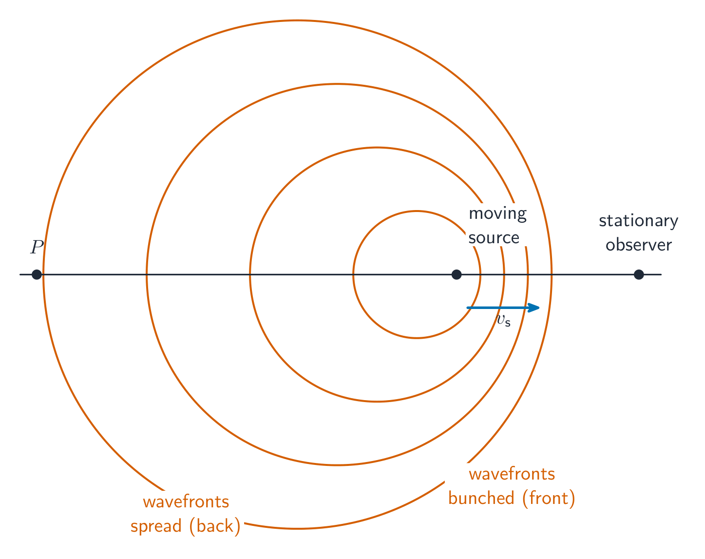
Syllabus
EnglishLearning Objective 14.5.A: Describe the properties of a wave based on the relative motion between the source of the wave and the observer of the wave.
- 14.5.A.1 The Doppler effect describes the relationship between the rest frequency of a wave source, the observed frequency of the source, and the relative velocity of the source and the observer.
- 14.5.A.2 A greater relative velocity results in a greater measured difference between the observed and rest frequencies.
- 14.5.A.2.i For a wave source moving at the same velocity as the observer, the observed frequency is equal to the rest frequency.
- 14.5.A.2.ii For a wave source moving toward an observer, the observed frequency is greater than the rest frequency.
- 14.5.A.2.iii For a wave source moving away from an observer, the observed frequency is less than the rest frequency.
Boundary statement: Only qualitative treatments of the Doppler effect are required for AP Physics 2.
한국어학습 목표 14.5.A: 파동원과 관측자 사이의 상대 운동에 근거하여 파동의 특성을 서술하시오.
- 14.5.A.1 도플러 효과는 파동원의 정지 주파수, 관측된 주파수, 그리고 파동원 및 관측자의 상대 속도 사이의 관계를 설명한다.
- 14.5.A.2 상대 속도가 클수록 관측된 주파수와 정지 주파수 사이의 차이 값이 커진다.
- 14.5.A.2.i 파동원이 관측자와 동일한 속도로 움직일 때, 관측된 주파수는 정지 주파수와 같다.
- 14.5.A.2.ii 파동관이 관측자에게 접근할 때, 관측된 주파수는 정지 주파수보다 크다.
- 14.5.A.2.iii 파동관이 관측자로부터 멀어질 때, 관측된 주파수는 정지 주파수보다 작다.
경계 문구: AP 물리학 2에서는 도플러 효과에 대한 정성적 설명만 요구한다.
Source: College Board AP Course and Exam Description · 출처: College Board AP Course and Exam Description
The Doppler effect The Doppler effect 多普勒效应 is the change in observed frequency when a wave source and observer move relative to each other. Approaching $\Rightarrow$ higher frequency (shorter wavelength); receding $\Rightarrow$ lower frequency. It explains a passing siren's drop in pitch and the redshift of receding galaxies.
A moving source squashes the wavefronts ahead of it, raising the observed frequency Explore · 탐색하기Hear the Doppler shift · 도플러 효과 듣기
When a source moves, waves bunch up ahead (higher frequency) and stretch behind (lower) — the Doppler effect. Speed it up to exaggerate the shift. · 파원이 이동하면 파동이 앞쪽에서 밀려서 주파수가 높아지고(higher frequency), 뒤쪽에서는 늘어나면서 주파수가 낮아집니다(lower). 이를 도플러 효과라고 합니다. 이 변화를 과장하여 확인하려면 속도를 높여보세요.
Vocabulary · 어휘 Train · 연습하기English 한국어 Doppler effect/ˈdɒplə ɪˈfekt/ 도플러 효과 14.6
Wave Interference and Standing Waves
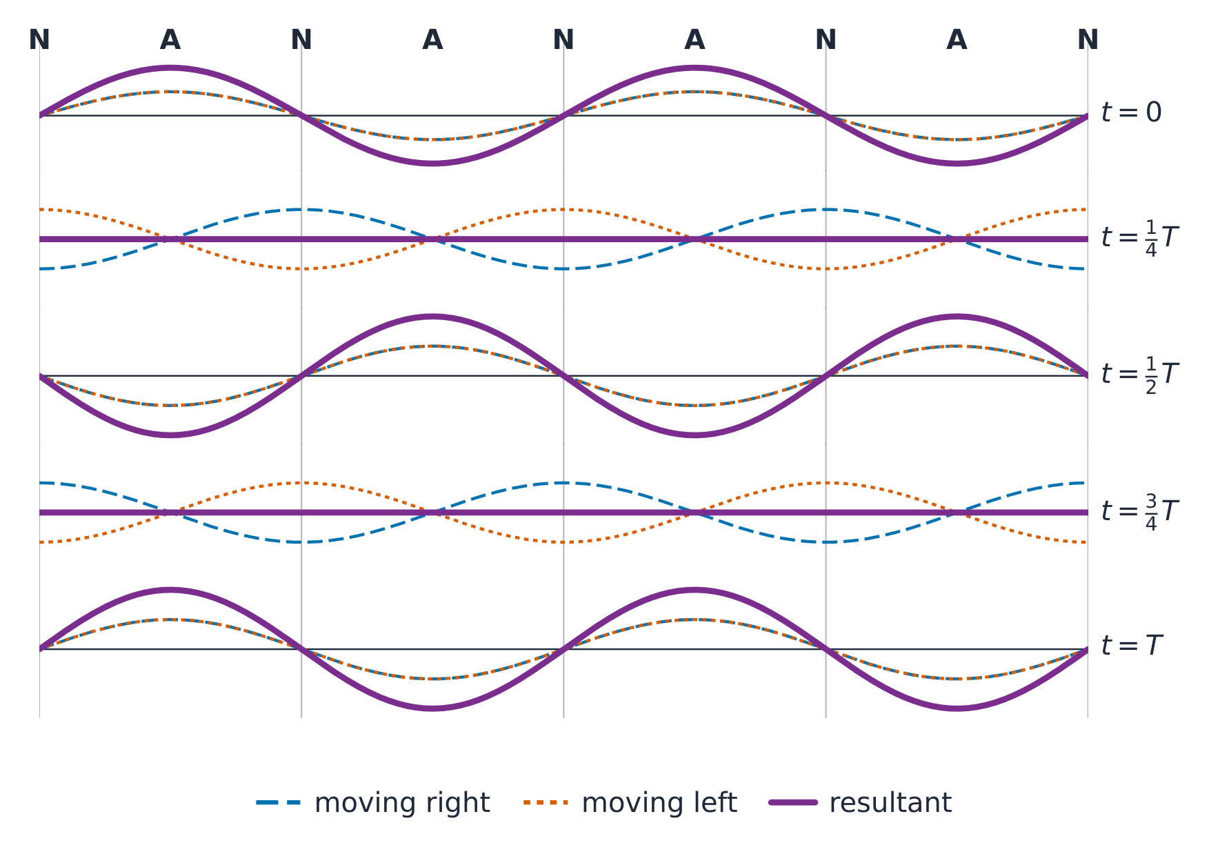
Syllabus
Learning Objective Essential Knowledge 14.6.A
Describe the net disturbance that occurs when two or more wave pulses or waves overlap.- 14.6.A.1 Wave interference is the interaction of two or more wave pulses or waves.
- 14.6.A.2 When two or more wave pulses or waves interact with each other, they travel through each other and overlap rather than bouncing off each other.
- 14.6.A.3 When two or more wave pulses or waves overlap, the resulting displacement can be determined by adding the individual displacements. This is called superposition.
- 14.6.A.4 Wave interference may be constructive or destructive.
- 14.6.A.4.i When the displacements of the superposed wave pulses or waves are in the same direction, the interaction is called constructive interference.
- 14.6.A.4.ii When the displacements of the superposed wave pulses or waves are in opposite directions, the interaction is called destructive interference.
- 14.6.A.4.iii Two or more traveling wave pulses or waves can interact in such a way as to produce amplitude variations in the resultant wave pulse or wave.
- 14.6.A.5 Visual representations of wave pulses or waves are useful in determining the result of two interacting wave pulses or waves.
- 14.6.A.6 Beats arise from the addition of two waves of slightly different frequency.
- 14.6.A.6.i Waves with different frequencies are sometimes in phase and sometimes out of phase at locations along the waves, causing periodic amplitude changes in the resultant wave.
- 14.6.A.6.ii The beat frequency is the difference in the frequencies of the two waves.
- Equation: $\left|f_{\text{beat}}\right| = \left|f_1 - f_2\right|$
- 14.6.A.6.iii Tuning forks are devices that are commonly used to demonstrate beat frequencies.
14.6.B
Describe the properties of a standing wave.- 14.6.B.1 Standing waves can result from interference between two waves that are confined to a region and traveling in opposite directions.
- 14.6.B.1.i Standing waves have nodes and antinodes. A node is a point on the standing wave where the amplitude is always zero. An antinode is a point on the standing wave where the amplitude is always at maximum.
- 14.6.B.1.ii The possible wavelengths of a standing wave are determined by the size and boundary conditions of the region to which it is confined.
- 14.6.B.1.iii Common regions where standing waves can form include pipes with open or closed ends, as well as strings with fixed or loose ends.
- 14.6.B.2 A standing wave with the longest possible wavelength is called the fundamental or first harmonic. The second-longest wavelength is typically called the second harmonic, the third-longest wavelength is called the third harmonic, and so on. However, for a standing wave with a node at one end and an antinode at the other end, only odd harmonics can be established.
- 14.6.B.3 Visual representations of standing waves are useful in determining the relationships between length of the region, wavelength, frequency, wave speed, and harmonic.
Source: College Board AP Course and Exam Description · 출처: College Board AP Course and Exam Description
Standing (stationary) waves When waves overlap they superpose (add). Constructive interference 相长干涉 (crests aligned) gives a bigger wave; destructive interference 相消干涉 (crest on trough) cancels. Two waves travelling opposite ways in a bounded medium form a standing wave 驻波 with fixed nodes 波节 (no motion) and antinodes 波腹 (maximum motion) – the basis of resonance on strings and in pipes.
A standing wave forms where two waves travelling in opposite directions overlap Worked example. A guitar string $0.65\ \text{m}$ long is fixed at both ends. Its fundamental (first harmonic) fits half a wavelength between the ends, so $\lambda=2L=1.30\ \text{m}$. If waves travel along the string at $260\ \text{m/s}$, the note's frequency is $f=v/\lambda=260/1.30=200\ \text{Hz}$. Shortening the string (a fret) raises the pitch.
When two waves of slightly different frequency overlap, they drift in and out of step, so the combined sound swells loud and soft in a slow throb called beats 拍. The beat frequency 拍频 is simply the difference of the two frequencies:
$$f_{\text{beat}}=|f_1-f_2|.$$Two tuning forks of $256\ \text{Hz}$ and $260\ \text{Hz}$ sounded together give $|260-256|=4$ beats each second; a musician tunes an instrument by slowing these beats towards zero against a reference note.Explore · 탐색하기Set up a standing wave · 정지 파동 만들기
Two waves travelling opposite ways interfere into a standing wave with fixed nodes and antinodes. Only certain frequencies fit, giving the harmonics. · 반대 방향으로 진행하는 두 파동이 간섭하여 고정된 결점과 복점이 있는 정지 파동을 만듭니다. 특정 주파수만 적합하여 조화를 생성합니다.
Vocabulary · 어휘 Train · 연습하기English 한국어 Constructive interference/kənˈstrʌktɪv ˌɪntəˈfɪərəns/ 간섭 강화 destructive interference/dɪˈstrʌktɪv ˌɪntəˈfɪərəns/ 간섭 소멸 standing wave/ˈstændɪŋ weɪv/ 정지파 nodes/nəʊdz/ 노드 antinodes/ˌæntɪˈnəʊdz/ 진폭 극대점 beats/biːts/ 비트 beat frequency/biːt ˈfriːkwənsi/ 박동 주파수 14.7
Diffraction
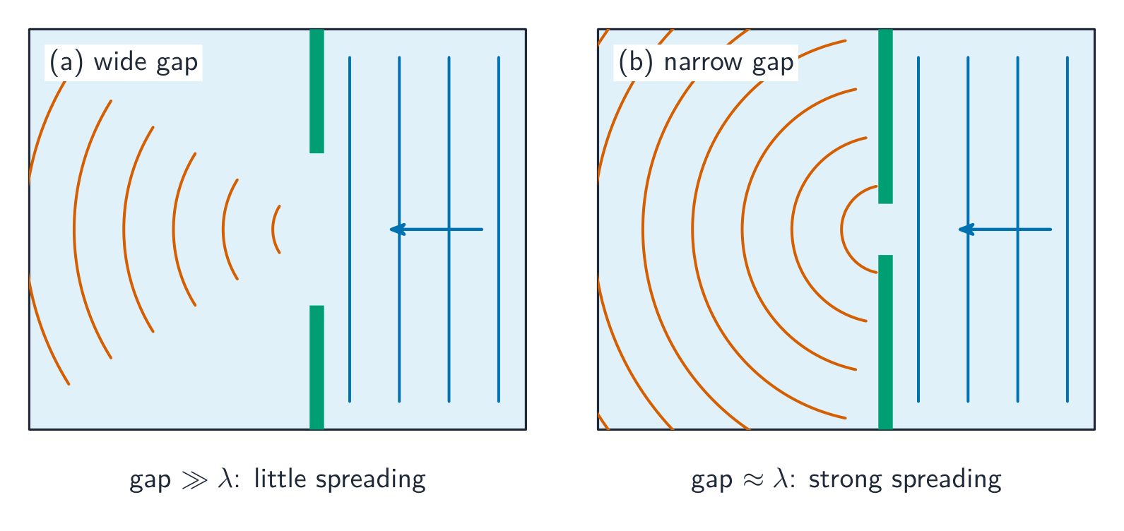
Syllabus
Learning Objective Essential Knowledge 14.7.A
Describe the behavior of a wave and the diffraction pattern resulting from a wave passing through a single opening.- 14.7.A.1 Diffraction is the spreading of a wave around the edges of an obstacle or through an opening.
- 14.7.A.2 Diffraction is most pronounced when the size of the opening is comparable to the wavelength of the wave.
- 14.7.A.3 Diffraction of multiple wavefronts through a single opening leads to observable interference patterns.
- 14.7.A.4 Diffraction is commonly demonstrated by monochromatic light of wavelength $\lambda$ incident on a narrow opening of width $a$ that is a distance $L$ from a screen.
- 14.7.A.4.i Constructive and destructive interference of multiple wavefronts originating from the opening will result in bright and dark bands on the screen.
- 14.7.A.4.ii The amount of interference between two wavefronts depends on the path length difference $\Delta D$ of the wavefronts.
- 14.7.A.4.iii The path length difference $\Delta D$ can be described in terms of the opening width $a$ and the angle $\theta$ between the direction of propagation of the wavefront and the normal to the opening by the equation $\Delta D = a\sin\theta$.
- 14.7.A.4.iv For small angles, where $\theta < 10°$, the small angle approximation can be used to relate $\lambda$, $a$, and $L$ to $y_{\min}$, the distance from the middle of the central bright fringe to the $m^{\text{th}}$ order of minimum brightness on the screen.
- Equation: $a\left(\dfrac{y_{\min}}{L}\right) \approx m\lambda$
- 14.7.A.5 The diffraction pattern produced by a wave passing through an opening depends on the shape of the opening.
- 14.7.A.6 Visual representations of single-slit diffraction patterns are useful in determining the physical properties of the slit and the interacting waves.
Source: College Board AP Course and Exam Description · 출처: College Board AP Course and Exam Description
Diffraction 衍射 is the bending and spreading of waves around edges or through openings. The spreading is significant when the opening is comparable to the wavelength – so sound (long wavelength) bends around doorways easily, while light (tiny wavelength) needs a very narrow slit.
Waves spread out (diffract) as they pass through a gap Vocabulary · 어휘 Train · 연습하기English 한국어 Diffraction/dɪˈfrækʃn/ 회절 14.8
Double-Slit Interference and Diffraction Gratings
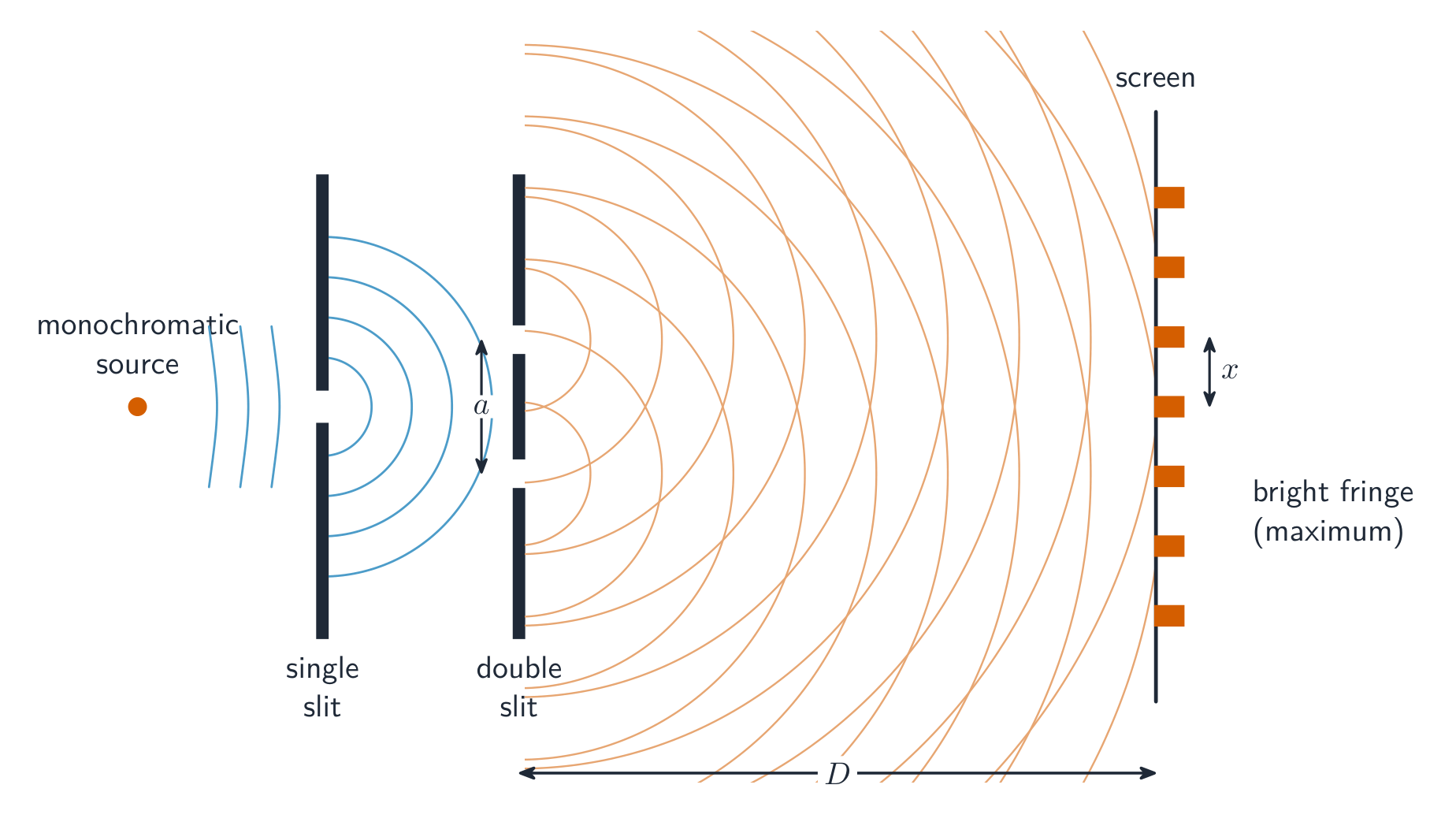
Syllabus
Learning Objective Essential Knowledge 14.8.A
Describe the behavior of a wave and the diffraction pattern resulting from the wave passing through multiple openings.- 14.8.A.1 The pattern resulting from monochromatic light of wavelength $\lambda$ incident on two slits a distance $d$ apart is caused by a combination of wave diffraction and wave interference.
- 14.8.A.1.i When only considering wave interference, a double slit creates a pattern of uniformly spaced maxima.
- 14.8.A.1.ii Constructive and destructive interference of the wavefronts originating from each slit will result in bright and dark bands on the screen.
- 14.8.A.1.iii The amount of interference between two wavefronts depends on the path length difference $\Delta D$ of the wavefronts.
- 14.8.A.1.iv The path length difference $\Delta D$ can be described in terms of the slit separation $d$ and the angle $\theta$ between the direction of propagation of the wavefront and the normal to the opening by the equation $\Delta D = d\sin\theta$.
- 14.8.A.1.v For small angles, where $\theta < 10°$, the small angle approximation can be used to relate $\lambda$, $d$, and $L$ to $y_{\max}$, the distance from the middle of the central bright fringe to the $m^{\text{th}}$ order of maximum brightness on the screen.
- Equation: $d\left(\dfrac{y_{\max}}{L}\right) \approx m\lambda$
- 14.8.A.1.vi When considering wave interference and wave diffraction, a double slit creates an interference pattern of maxima and minima superimposed within the envelope created by single-slit diffraction.
- 14.8.A.2 Interference patterns produced by light interacting with a double slit indicate that light has wave properties. The source of this discovery was Young's double-slit experiment.
- 14.8.A.3 Visual representations of double-slit diffraction patterns are useful in determining the physical properties of the slits and the interacting waves.
- 14.8.A.4 A diffraction grating is a collection of evenly spaced parallel slits or openings that produce an interference pattern that is the combination of numerous diffraction patterns superimposed on each other.
- 14.8.A.5 When white light is incident on a diffraction grating, the center maximum is white and the higher-order maxima disperse white light into a rainbow of colors, with the longest-wavelength light (red) appearing farthest from the central maximum.
Source: College Board AP Course and Exam Description · 출처: College Board AP Course and Exam Description
Two-source interference Coherent 相干 light through two closely spaced slits produces a pattern of bright and dark fringes. Bright fringes occur where the path difference is a whole number of wavelengths:
$$d\sin\theta=m\lambda.$$A diffraction grating 衍射光栅 has many slits, giving sharp, widely spaced bright lines – useful for separating light into its wavelengths.Young's double slits give an interference pattern of bright and dark fringes Worked example. Light of wavelength $600\ \text{nm}$ passes through two slits $0.20\ \text{mm}$ apart. The first bright fringe ($m=1$) sits at
$$\sin\theta=\frac{m\lambda}{d}=\frac{1\times600\times10^{-9}}{0.20\times10^{-3}}=3.0\times10^{-3}\;\Rightarrow\;\theta=0.17^{\circ}.$$The tiny angle is why the slits must be very close together and the screen far away to see the fringes clearly.
The fine tracks on a CD act as a diffraction grating, splitting white light into a spectrum Explore · 탐색하기Superpose two waves · 두 파동을 중첩하다
Where two waves arrive in phase they add (bright fringe); out of phase they cancel (dark fringe). That interference makes the double-slit pattern. · 두 파동이 **동위(in phase)**로 도달하면 서로 더하여 **밝은 간섭 무늬(bright fringe)**를 만들고, **이위(out of phase)**로 도달하면 서로 상쇄되어 **어두운 간섭 무늬(dark fringe)**를 만듭니다. 이러한 간섭 현상이 이중슬릿 패턴을 형성합니다.
Vocabulary · 어휘 Train · 연습하기English 한국어 Coherent/kəʊˈhɪərənt/ 간섭성 있는 diffraction grating/dɪˈfrækʃn ˈɡreɪtɪŋ/ 회절 격자 14.9
Thin-Film Interference
Syllabus
Learning Objective Essential Knowledge 14.9.A
Describe the behavior of light that interacts with a thin film.- 14.9.A.1 When light travels from one medium to another, some of the light is transmitted, some is reflected, and some is absorbed.
- 14.9.A.2 The phase change of a reflected ray depends on the relative indices of refraction of the materials with which the ray interacts.
- 14.9.A.2.i A phase change of 180 degrees occurs when a light ray is reflected from a medium with a greater index of refraction than the medium through which the ray is traveling.
- 14.9.A.2.ii No phase change occurs when a light ray is reflected from a medium with a lower index of refraction than the medium through which the ray is traveling.
- 14.9.A.3 The phase of a wave does not change when it is refracted as it passes from one medium into another.
- 14.9.A.4 Thin-film interference occurs when light interacts with a medium whose thickness is comparable to the light's wavelength.
- 14.9.A.4.i The interactions between the initial reflected light and the light exiting the thin film after being reflected from the second interface exhibit wave interference behavior, resulting in a single wave that is the sum of the two interacting waves.
- 14.9.A.4.ii The amount of constructive or destructive interference between the two reflected waves depends on the relationship between the thickness of the film, the wavelength of light, any phase shifts, and the angle at which the incident light strikes the film.
- 14.9.A.5 Practical examples of thin-film interference include the color variations seen in soap bubbles and oil films, as well as antireflection coatings.
- 14.9.A.5.i The spectrum of colors observed in oil films and soap bubbles arises from differences in the thickness of the film.
- 14.9.A.5.ii Antireflection coatings eliminate reflected light by applying the relationships between indices of refraction, phase shift, and wave interference to create destructive interference of the light reflected from the two surfaces of the coating.
- 14.9.A.5.iii The simplest antireflection coating has a thickness equal to one-quarter of the wavelength of the light in the coating, and the index of refraction of the coating is greater than that of air and less than that of the surface upon which the coating is applied. This assumes incident light is normal to the surface.
Boundary statement: Quantitative analysis of thin-film interference is limited to waves that are normal to the incident surface.
Source: College Board AP Course and Exam Description · 출처: College Board AP Course and Exam Description
Light reflecting off the top and bottom of a thin film 薄膜 (soap bubble, oil slick) interferes with itself. Depending on the film's thickness and a possible half-wavelength phase flip on reflection off a denser medium, particular wavelengths interfere constructively – producing the shifting colours you see.
The same physics is put to work in an antireflection coating 增透膜 on camera lenses, glasses, and solar cells: a thin transparent layer whose two reflected waves interfere destructively, so almost no light reflects and more is transmitted. The simplest coating is one quarter of a wavelength thick (measured in the coating), and its refractive index sits between that of air and the glass beneath, so the reflected light cancels itself out.
Vocabulary · 어휘 Train · 연습하기English 한국어 thin film/θɪn fɪlm/ 박막 antireflection coating/ˌæntɪrɪˈflekʃn ˈkəʊtɪŋ/ 반사 방지 코팅 14.9
Exam tips
- Use $v=f\lambda$; the source sets the frequency, and when a wave enters a new medium the frequency stays fixed while the speed and wavelength change.
- Distinguish transverse (vibration perpendicular, can be polarised) from longitudinal (vibration along the travel, e.g. sound).
- Constructive interference needs a path difference of a whole number of wavelengths; destructive needs a half-odd number.
- On a string fixed at both ends the fundamental fits half a wavelength ($\lambda=2L$).
- Diffraction is significant only when the gap is comparable to the wavelength — sound bends round doorways, light needs a very narrow slit.
- Beats: two waves of slightly different frequency throb at $f_{\text{beat}}=|f_1-f_2|$ (e.g. two tuning forks; tuning to zero beats).
- An antireflection coating is a quarter-wavelength-thick layer (index between air and glass) whose two reflections cancel, cutting the reflected light.
- 14.1.A.1 Waves transfer energy between two locations without transferring matter between those locations.
-
15
Modern Physics
Watch lesson · 수업 보기15.1
Quantum Theory and Wave-Particle Duality
Syllabus
EnglishLearning Objective 15.1.A: Describe the properties and behavior of an object that exhibits both particle-like and wave-like behavior.
- 15.1.A.1 Quantum theory was developed to explain observations of matter and energy that could not be explained using classical mechanics. These phenomena include, but are not limited to, atomic spectra, blackbody radiation, and the photoelectric effect.
- 15.1.A.1.i Quantum theory is necessary to describe the properties of matter at atomic and subatomic scales.
- 15.1.A.1.ii In quantum theory, fundamental particles can exhibit both particle-like and wave-like behavior.
- 15.1.A.2 Light can be modeled both as a wave and as discrete particles, called photons.
- 15.1.A.2.i A photon is a massless, electrically neutral particle with energy proportional to the photon's frequency.
- Relevant equations:
- $E = hf$
- $\lambda = \dfrac{c}{f}$
- 15.1.A.2.ii Photons travel in straight lines unless they interact with matter.
- 15.1.A.2.i A photon is a massless, electrically neutral particle with energy proportional to the photon's frequency.
- 15.1.A.3 The speed of a photon depends on the medium through which the photon travels.
- 15.1.A.3.i The speed of all photons in free space is equal to the speed of light, $c = 3.00 \times 10^{8}$ m/s.
- 15.1.A.3.ii In general, the speed of photons through a given medium is inversely proportional to the index of refraction of that medium.
- 15.1.A.4 Particles can demonstrate wave properties, as shown by variations of Young's double-slit experiment.
- 15.1.A.4.i A wave model of matter is quantified by the de Broglie wavelength, which increases as the momentum of a particle decreases.
- Relevant equation:
- $\lambda = \dfrac{h}{p}$
- 15.1.A.4.ii Quantum theory is necessary to describe systems where the de Broglie wavelength is comparable to the size of the system.
- 15.1.A.4.i A wave model of matter is quantified by the de Broglie wavelength, which increases as the momentum of a particle decreases.
- 15.1.A.5 Values of energy and momentum have discrete, or quantized, values for bound systems described by quantum theory.
한국어학습 목표 15.1.A: 입자적 성질과 파동적 성질을 모두 나타내는 물체의 특성과 거동을 설명하시오.
- 15.1.A.1 양자 이론은 고전 역학으로는 설명할 수 없는 물질과 에너지에 대한 관측 결과를 설명하기 위해 개발되었습니다. 이러한 현상에는 원 스펙트럼, 흑체 복사, 그리고 광전 효과가 포함되지만 이에 국한되지 않습니다.
- 15.1.A.1.i 양자 이론은 원자 및 아원자スケール에서의 물질의 특성을 설명하는 데 필수적입니다.
- 15.1.A.1.ii 양자 이론에서 기본 입자는 입자적 성질과 파동적 성질을 모두 나타낼 수 있습니다.
- 15.1.A.2 빛은 파동으로 모델링될 수도 있고, 광자(photon)라고 불리는 이산적 입자로 모델링될 수도 있습니다.
- 15.1.A.2.i 광자는 질량이 없고 전기적으로 중성인 입자로서, 에너지는 광자의 주파수에 비례합니다.
- *관련 식:
- $E = hf$
- $\lambda = \dfrac{c}{f}$
- 15.1.A.2.ii 광자는 물질과 상호작용하지 않는 한 직선으로 진행합니다.
- 15.1.A.2.i 광자는 질량이 없고 전기적으로 중성인 입자로서, 에너지는 광자의 주파수에 비례합니다.
- 15.1.A.3 광자의 속도는 광자가 통과하는 매질에 따라 달라집니다.
- 15.1.A.3.i 진공 공간中的所有의 광자의 속도는光速 $c = 3.00 \times 10^{8}$ m/s와 같습니다.
- 15.1.A.3.ii 일반적으로 특정 매질을 통한 광자의 속도는 해당 매질의 굴절률에 반비례합니다.
- 15.1.A.4 입자는 영의 이중슬릿 실험의 변형 등을 통해 파동적 성질을 나타낼 수 있습니다.
- 15.1.A.4.i 물질의 파동 모델은 드브로이 파장으로 정량화되며, 이는 입자의 운동량이 감소함에 따라 증가합니다.
- *관련 식:
- $\lambda = \dfrac{h}{p}$
- 15.1.A.4.ii 드브로이 파장이 시스템의 크기와 비교 가능한 수준일 때 양자 이론은 해당 시스템을 설명하는 데 필수적입니다.
- 15.1.A.4.i 물질의 파동 모델은 드브로이 파장으로 정량화되며, 이는 입자의 운동량이 감소함에 따라 증가합니다.
- 15.1.A.5 양자 이론으로 기술된 결합 시스템에서 에너지와 운동량의 값은 이산적, 즉 양자화된 값을 가집니다.
Source: College Board AP Course and Exam Description · 출처: College Board AP Course and Exam Description
A cloud chamber: modern physics tracks charged particles from radioactive decays At tiny scales, energy comes in discrete packets called quanta 量子. Light is carried by photons 光子, each with energy set by its frequency:
$$E=hf,$$where $h$ is Planck's constant. Wave–particle duality 波粒二象性: light and matter each show both wave behavior (interference, diffraction) and particle behavior (photons, electrons as localized hits). A particle also has a matter wavelength $\lambda=\dfrac{h}{p}$, and particles genuinely produce interference - a variation of Young's double-slit experiment 双缝实验 done with electrons builds up the same fringe pattern as light.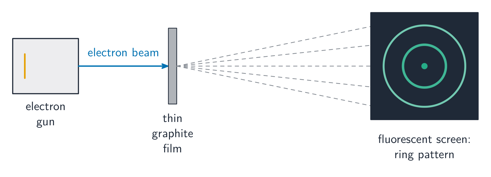
Electrons form a diffraction pattern, showing that particles have a wave nature Worked example. Find the energy of a photon of orange light with frequency $5.0\times10^{14}\ \text{Hz}$ ($h=6.63\times10^{-34}\ \text{J s}$): $E=hf=6.63\times10^{-34}\times5.0\times10^{14}=3.3\times10^{-19}\ \text{J}$, which is about $2.1\ \text{eV}$ (dividing by $1.6\times10^{-19}$). Visible-light photons carry a few electronvolts – just right to trigger the chemistry of vision and photosynthesis.
Vocabulary · 어휘 Train · 연습하기English 한국어 quanta/ˈkwɒntə/ 양자 photons/ˈfəʊtɒnz/ 광자 Wave–particle duality/weɪv ˈpɑːtɪkl djuːˈælɪti/ 파동-입자 이중성 double-slit experiment/ˈdʌbl slɪt ekˈsperɪmənt/ 이중 슬릿 실험 15.2
The Bohr Model of Atomic Structure
Syllabus
EnglishLearning Objective 15.2.A: Describe the properties of an atom.
- 15.2.A.1 Atoms have internal structure.
- 15.2.A.1.i Atoms consist of a small, positively charged nucleus surrounded by one or more negatively charged electrons.
- 15.2.A.1.ii The nucleus of an atom is made up of protons and neutrons.
- 15.2.A.1.iii The number of neutrons and protons in an atom can be represented using nuclear notation.
- 15.2.A.1.iv An ion is an atom with a nonzero net electric charge.
- 15.2.A.2 Each atomic element has a unique number of protons.
- 15.2.A.2.i The number and arrangements of electrons affects how atoms interact.
- 15.2.A.2.ii The total number of neutrons and protons identifies the isotope of an element.
- 15.2.A.2.iii The mass of an atom is dominated by the total mass of the protons and neutrons in its nucleus.
- 15.2.A.3 The Bohr model of the atom is based on classical physics and was the historical representation of the atom that led to the description of the hydrogen atom in terms of discrete energy states.
- 15.2.A.3.i In the Bohr model of the atom, electrons are modeled as moving around the nucleus in circular orbits determined by the electron's charge and mass, as well as the electric force between the electron and the nucleus.
- Relevant equations:
- $F_e = k\dfrac{q_1 q_2}{r^2}$
- $F_{\text{net}} = m\dfrac{v^2}{r}$
- 15.2.A.3.ii The standing wave model of electrons accounts for the existence of specific allowed energy states of an electron in an atom, because the electron orbit's circumference must be an integer multiple of the electron's de Broglie wavelength.
- 15.2.A.3.i In the Bohr model of the atom, electrons are modeled as moving around the nucleus in circular orbits determined by the electron's charge and mass, as well as the electric force between the electron and the nucleus.
Boundary statement: The analysis and description of electron structure is limited to energy levels and will not include such advanced descriptions as orbitals, orbital shapes, or probability functions.
한국어학습 목표 15.2.A: 원자의 특성을 설명하시오.
- 15.2.A.1 원자는 내부 구조를 가집니다.
- 15.2.A.1.i 원자는 작고 양전하를 띤 핵과 그 주변을 돌고 있는 하나 이상의 음전하를 띤 전자로 구성됩니다.
- 15.2.A.1.ii 원자의 핵은 양성자와 중성자로 이루어져 있습니다.
- 15.2.A.1.iii 원자 내의 중성자와 양성자의 수는 핵 표기법을 사용하여 표현할 수 있습니다.
- 15.2.A.1.iv 이온은 비영점 전기 하전을 가진 원자이다.
- 15.2.A.2 각 원소마다 고유한 수의 양성자를 가집니다.
- 15.2.A.2.i 전자의 수와 배치는 원자가 상호작용하는 방식에 영향을 미친다.
- 15.2.A.2.ii 중성자와 양성자의 총 개수는 해당 원소의 동위 원소를 식별한다.
- 15.2.A.2.iii 원자의 질량은 핵 내의 양성자와 중성자의 질량 총합에 의해 지배받는다.
- 15.2.A.3 보어의 원자 모델은 고전 역학에 기반을 두고 있으며, 수소 원자를 이산화된 에너지 상태로 기술하게 된 역사적인 원자 표현법이다.
- 15.2.A.3.i 보어의 원자 모델에서 전자는 전하와 질량뿐만 아니라 전자와 핵 사이의 전기적 힘에 의해 결정된 원형 궤도를 따라 핵 주위를 돌고 있는 것으로 모델링된다.
- *관련 식:
- $F_e = k\dfrac{q_1 q_2}{r^2}$
- $F_{\text{net}} = m\dfrac{v^2}{r}$
- 15.2.A.3.ii 전자의 정지파 모델은 전자의 드 브로이 파장이 궤도의 둘레 길이에 대한 정수배여야 하므로, 원자 내 전자의 특정 허용 에너지 상태가 존재함을 설명한다.
- 15.2.A.3.i 보어의 원자 모델에서 전자는 전하와 질량뿐만 아니라 전자와 핵 사이의 전기적 힘에 의해 결정된 원형 궤도를 따라 핵 주위를 돌고 있는 것으로 모델링된다.
경계문: 전자 구조의 분석과 설명은 에너지 준위에 국한되며, 궤도함수, 궤도 모양 또는 확률 함수와 같은 고급 서술은 포함되지 않는다.
Source: College Board AP Course and Exam Description · 출처: College Board AP Course and Exam Description
The Bohr model 玻尔模型 pictures electrons orbiting the nucleus only in certain allowed energy levels 能级. An electron can jump between levels only by absorbing or emitting a photon whose energy exactly matches the gap:
$$E_{\text{photon}}=|E_{\text{final}}-E_{\text{initial}}|.$$Because the levels are discrete, only specific photon energies are allowed.Vocabulary · 어휘 Train · 연습하기English 한국어 Bohr model/ˈbəʊə ˈmɒdl/ 보어 모델 energy levels/ˈenədʒi ˈlevlz/ 에너지 수준 15.3
Emission and Absorption Spectra
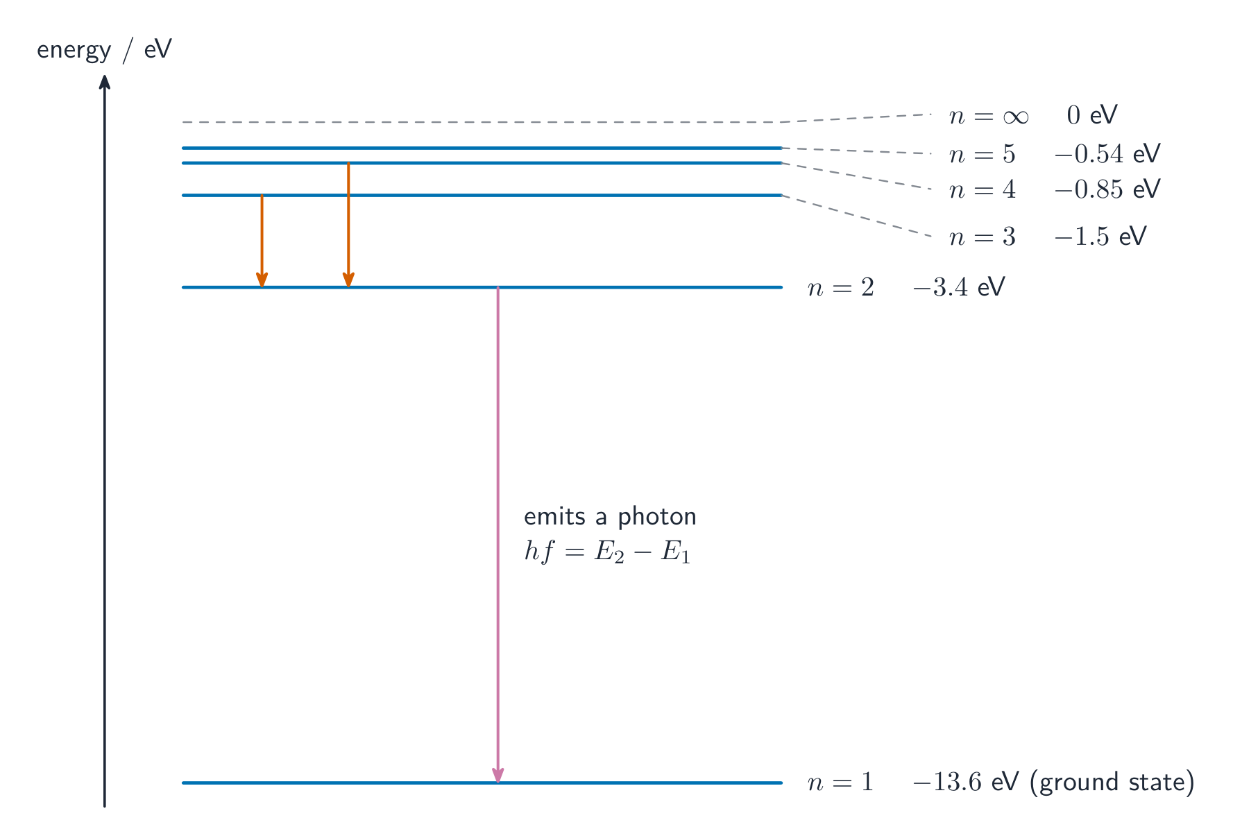
Syllabus
EnglishLearning Objective 15.3.A: Describe the emission or absorption of photons by atoms.
- 15.3.A.1 Energy transfer occurs when photons are absorbed or emitted by an atom, which is modeled as a system consisting of a nucleus and an electron.
- 15.3.A.2 Energy can only be absorbed or emitted by an atom if the amount of energy being absorbed or emitted corresponds to the energy difference between two atomic energy states.
- 15.3.A.2.i An atom in a given energy state may absorb a photon of the appropriate energy and transition to a higher energy state.
- 15.3.A.2.ii An atom in an excited energy state may emit a photon of the appropriate energy to spontaneously move to a lower energy state.
- 15.3.A.2.iii Because an atom is modeled as a system consisting of an electron and a nucleus, a change in the energy state of an atom corresponds to a change in the interaction energy between the electron and the nucleus.
- 15.3.A.3 Transitions between two energy states of an atom correspond to the absorption or emission of a photon of a single frequency and, therefore, a single wavelength.
- 15.3.A.4 Atoms of each element have a unique set of allowed energy levels and thereby a unique set of absorption and emission frequencies. The unique set of frequencies determines the element's spectrum.
- 15.3.A.4.i An emission spectrum can be used to determine the elements in a source of light.
- 15.3.A.4.ii An absorption spectrum can be used to determine the elements composing a substance by observing what light the substance has absorbed.
- 15.3.A.4.iii Energy level diagrams are commonly used to visually represent the energy states of an atom.
- 15.3.A.5 Binding energy is the energy required to remove an electron from an atom, causing the atom to become ionized. An atom in the lowest energy level (ground state) will require the greatest amount of energy to remove the electron from the atom.
Boundary statement: In AP Physics 2, only energy level diagrams of single-electron atoms will be considered.
한국어학습 목표 15.3.A: 원자에 의한 광자의 방출 또는 흡수를 서술하라.
- 15.3.A.1 원자가 광자를 흡수하거나 방출할 때 에너지 전달이 일어나며, 이는 핵과 전자로 구성된 시스템으로 모델링된다.
- 15.3.A.2 원자가 흡수하거나 방출할 수 있는 에너지는 반드시 두 원자 에너지 상태 사이의 에너지 차이와 일치해야 한다.
- 15.3.A.2.i 특정한 에너지 상태에 있는 원자는 적절한 에너지를 가진 광자를 흡수하여 높은 에너지 상태로 전이할 수 있다.
- 15.3.A.2.ii 여기된 에너지 상태에 있는 원자는 적절한 에너지를 가진 광자를 자발적으로 방출하여 낮은 에너지 상태로 이동할 수 있다.
- 15.3.A.2.iii 원자는 전자와 핵으로 구성된 시스템으로 모델링되므로, 원자의 에너지 상태 변화는 전자와 핵 간의 상호작용 에너지 변화를 의미한다.
- 15.3.A.3 원자의 두 에너지 상태 간 전이는 단일 주파수와 따라서 단일 파장을 가지는 광자의 흡수 또는 방출에 해당한다.
- 15.3.A.4 각 원소의 원자는 고유한 허용 에너지 준위의 집합을 가지므로, 고유한 흡수 및 방출 주파수의 집합을 갖게 된다. 이러한 고유한 주파수의 집합이 해당 원소의 스펙트럼을 결정한다.
- 15.3.A.4.i 방출 스펙트럼을 사용하여 빛의 원천에 포함된 원소를 파악할 수 있다.
- 15.3.A.4.ii 흡수 스펙트럼을 사용하여 물질이 어떤 빛을 흡수했는지 관찰함으로써 물질을 구성하는 원소를 파악할 수 있다.
- 15.3.A.4.iii 에너지 준위 도표는 일반적으로 원자의 에너지 상태를 시각적으로 표현하는 데 사용된다.
- 15.3.A.5 결합 에너지는 원자로부터 전자를 제거하여 원자를 이온화시키는 데 필요한 에너지이다. 가장 낮은 에너지 준위(기저 상태)에 있는 원자는 전자를 제거하는 데 가장 많은 에너지를 요구한다.
경계문: AP 물리학 2에서는 단일 전자 원자의 에너지 준위 도표만 고려한다.
Source: College Board AP Course and Exam Description · 출처: College Board AP Course and Exam Description
- An emission spectrum 发射光谱 is the set of bright lines given off when electrons drop to lower levels – each line a specific wavelength.
- An absorption spectrum 吸收光谱 is the set of dark lines where those same wavelengths are absorbed from a continuous source.
The discrete energy levels of hydrogen produce a line spectrum The line pattern is a fingerprint of the element, since every element has its own energy levels.

Hydrogen's emission spectrum: each bright line is light from an electron dropping between fixed energy levels Explore · 탐색하기See an element's line spectrum · 원소의 선 스펙트럼(line spectrum) 보기
Electrons jump between fixed energy levels, emitting or absorbing photons of exact wavelengths — a line spectrum that fingerprints the element. · 전자들이 고정된 에너지 준위를 오가며 특정 파장의 광자를 방출하거나 흡수합니다. 이는 해당 원소만의 지문과 같은 선 스트럼입니다.
Vocabulary · 어휘 Train · 연습하기English 한국어 emission spectrum/ɪˈmɪʃn ˈspektrəm/ 방출 스펙트럼 absorption spectrum/əbˈsɔːpʃn ˈspektrəm/ 흡수 스펙트럼 15.4
Blackbody Radiation
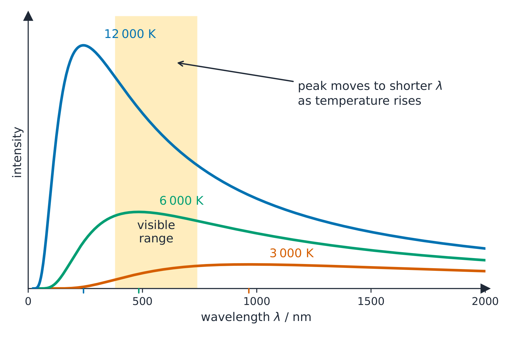
Syllabus
Learning Objective Essential Knowledge 15.4.A
Describe the electromagnetic radiation emitted by an object due to its temperature.- 15.4.A.1 Matter will spontaneously convert some of its internal thermal energy into electromagnetic energy.
- 15.4.A.2 A blackbody is an idealized model of matter that absorbs all radiation that falls on the body. If the body is in equilibrium at a constant temperature, then it must in turn emit energy.
- 15.4.A.3 A blackbody will emit a continuous spectrum that only depends on the body's temperature. The radiation emitted by a blackbody is often modeled by plotting intensity per unit wavelength as a function of wavelength.
- 15.4.A.3.i The distribution of the intensity of a blackbody's spectrum as a function of temperature cannot be modeled using only classical physics concepts. A blackbody's spectrum is described by Planck's law, which assumes that the energy of light is quantized.
- 15.4.A.3.ii The peak wavelength emitted by a blackbody (the wavelength at which the blackbody emits the greatest amount of radiation per unit wavelength) decreases with increasing temperature, as described by Wien's law.
- Relevant equation:
- $\lambda_{\max} = \dfrac{b}{T}$
- 15.4.A.3.iii The rate at which energy is emitted (power) by a blackbody is proportional to the surface area of the body and to the temperature of the body raised to the fourth power, as described by the Stefan-Boltzmann law.
- Relevant equation:
- $P = A\sigma T^4$
Source: College Board AP Course and Exam Description · 출처: College Board AP Course and Exam Description
A blackbody 黑体 emits a continuous spectrum that depends only on its temperature. Hotter objects glow brighter and peak at shorter wavelengths (red-hot to white-hot to blue-hot). Explaining this spectrum required quantized energy – a founding problem of quantum theory.
A hotter black body radiates more, and its peak shifts to shorter wavelengths Vocabulary · 어휘 Train · 연습하기English 한국어 blackbody/ˈblækbɒdi/ 흑체 15.5
The Photoelectric Effect
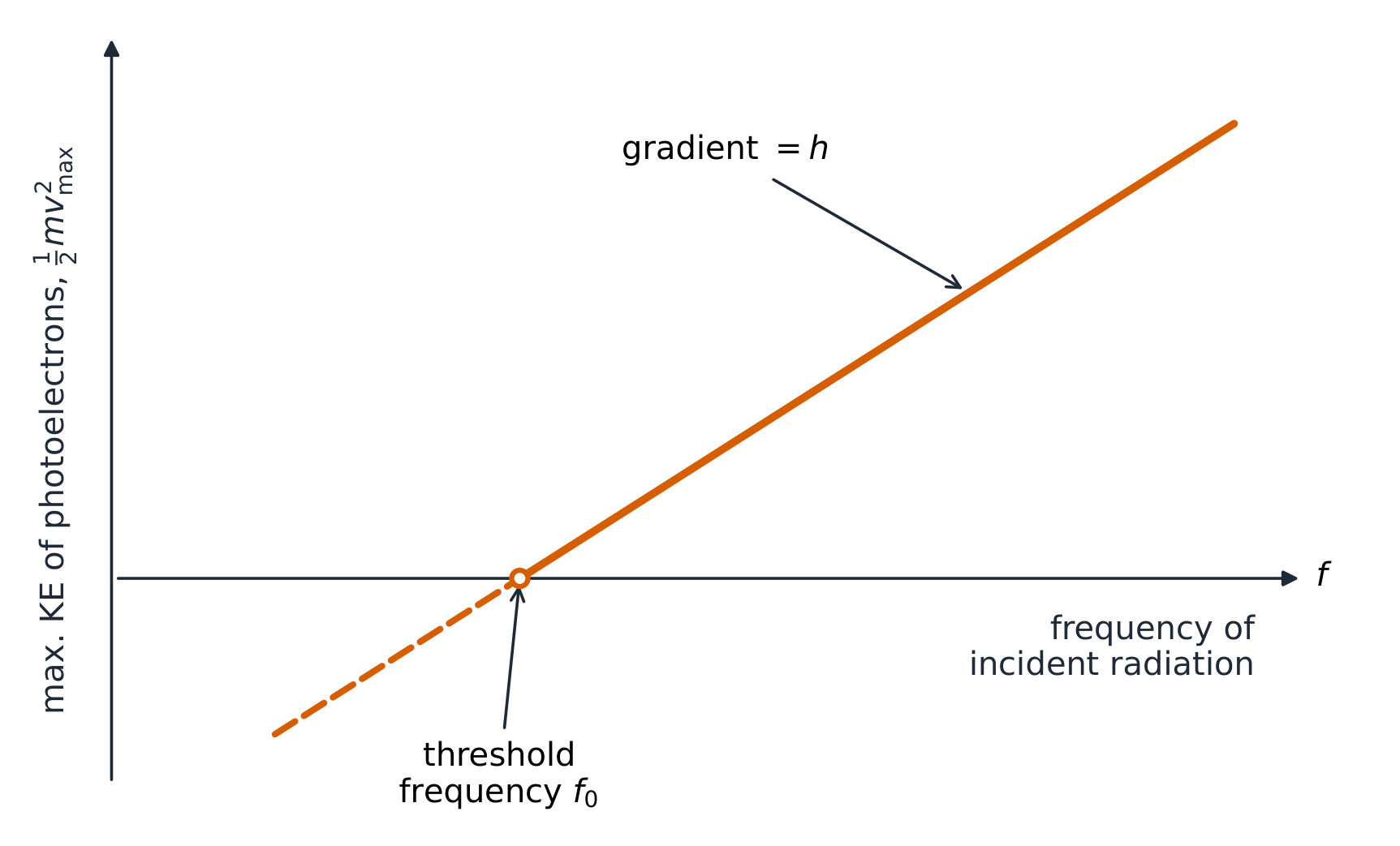
Syllabus
EnglishLearning Objective 15.5.A: Describe an interaction between photons and matter using the photoelectric effect.
- 15.5.A.1 The photoelectric effect is the emission of electrons when electromagnetic radiation is incident upon a photoactive material.
- 15.5.A.2 The emission of electrons via the photoelectric effect requires a minimum frequency of incident light, called the threshold frequency.
- 15.5.A.2.i Light that is incident on a material and is at the threshold frequency or higher will induce electron emission, regardless of the number of photons that strike the material.
- 15.5.A.2.ii The energy of the emitted electrons is not dependent on the number of photons that are incident upon the material, which provides evidence that light is a collection of discrete, quantized energy packets called photons.
- 15.5.A.3 The maximum kinetic energy of an emitted electron is related to the frequency of the incident light and the work function of the material, $\phi$.
- 15.5.A.3.i The work function of a material is the minimum energy required to emit an electron from atoms in the material.
- 15.5.A.3.ii The maximum kinetic energy of an emitted electron is given by the equation $K_{\max} = hf - \phi$.
- 15.5.A.3.iii In a typical experimental setup to demonstrate the photoelectric effect and determine the work function of a metal, two metal plates are placed in a vacuum chamber and connected to a variable source of potential difference. One of the plates is illuminated by monochromatic light that causes electrons to be ejected and the potential difference between the plates is adjusted until no current is measured in the circuit.
Boundary statement: Where applicable, work functions for materials will be provided on the exam; students are not expected to know values of work functions or variables of a material that influence the magnitude of its work function.
한국어학습 목표 15.5.A: 광전자 효과를 통해 광자와 물질 간의 상호작용을 서술하라.
- 15.5.A.1 광전자 효과는 전자기 복사가 광활성 물질에 입사할 때 전자가 방출되는 현상이다.
- 15.5.A.2 광전자 효과에 의한 전자 방출에는 임계 주파수라고 불리는 입사광의 최소 주파수가 필요하다.
- 15.5.A.2.i 물질에 입사하여 임계 주파수 이상인 빛은 물질에撞击하는 광자의 수와 관계없이 전자 방출을 유발한다.
- 15.5.A.2.ii 방출된 전자의 에너지는 입사하는 광자의 수에 의존하지 않으며, 이는 빛이 광자라고 불리는 이산적이고 양자화된 에너지 덩어리의 집합임을 시사하는 증거이다.
- 15.5.A.3 방출된 전자의 최대 운동에너지는 입사광의 주파수와 물질의 일함수 $\phi$과 관련이 있다.
- 15.5.A.3.i 물질의 일함수는 해당 물질의 원자로부터 전자를 방출하는 데 필요한 최소 에너지량이다.
- 15.5.A.3.ii 방출된 전자의 최대 운동에너지는 식 $K_{\max} = hf - \phi$에 의해 주어진다.
- 15.5.A.3.iii 광전 효과를 시연하고 금속의 일함수를 결정하기 위한 일반적인 실험 장치에서는 두 개의 금속 판을 진공 챔버에 배치하여 전위차 가변원에 연결한다. 하나의 판을 단색광으로 조사하여 전자가 방출되게 하고, 회로에서 전류가 측정되지 않도록 판 사이의 전위차를 조절한다.
경계 문항: 적용 가능한 경우, 시험에서 물질의 일함수는 제공되며, 학생들은 일함수의 값이나 물질의 일함수 크기에 영향을 미치는 변수를 알 필요는 없다.
Source: College Board AP Course and Exam Description · 출처: College Board AP Course and Exam Description
The photoelectric effect Shining light on a metal can eject electrons – the photoelectric effect 光电效应. Key facts (which only the photon picture explains): electrons come out only if the photon's frequency exceeds a threshold, no matter how bright a dimmer, lower-frequency light is. Energy conservation gives
$$K_{\max}=hf-\phi,$$where $\phi$ is the metal's work function 逸出功 (the energy to free an electron).The maximum kinetic energy of photoelectrons rises linearly with frequency Worked example. Light of frequency $8.0\times10^{14}\ \text{Hz}$ falls on a metal with work function $\phi=3.0\times10^{-19}\ \text{J}$. The most energetic electrons come off with
$$K_{\max}=hf-\phi=(6.63\times10^{-34}\times8.0\times10^{14})-3.0\times10^{-19}=5.3\times10^{-19}-3.0\times10^{-19}=2.3\times10^{-19}\ \text{J}.$$Below the threshold frequency $\phi/h$, $K_{\max}$ would be negative – meaning no electrons escape at all, however bright the light.Vocabulary · 어휘 Train · 연습하기English 한국어 photoelectric effect/ˌfəʊtəʊɪˈlektrɪk ɪˈfekt/ 광전 효과 work function/wɜːk ˈfʌŋkʃn/ 일함수(WORK FUNCTION) 15.6
Compton Scattering
Syllabus
EnglishLearning Objective 15.6.A: Describe the interaction between photons and matter using Compton scattering.
- 15.6.A.1 In Compton scattering, a photon interacts with a free electron. The Compton effect is when a photon that emerges from the interaction has a lower energy and longer wavelength than the incoming photon. The magnitude of the change is related to the direction of the photon after the collision.
- 15.6.A.2 Compton scattering provides evidence that light is a collection of discrete, quantized energy packets called photons.
- 15.6.A.2.i Compton scattering can be explained by treating a photon as a particle and applying conservation of energy and conservation of momentum to the collision between the photon and electron.
- 15.6.A.2.ii The transfer of a photon's energy to an electron results in the energy, momentum, frequency, and wavelength of the photon changing.
- Relevant equations:
- $E = hf$
- $\lambda = \dfrac{h}{p}$
- 15.6.A.3 The change in wavelength experienced by a photon after colliding with an electron is related to how much the photon's direction changes.
- Relevant equation:
- $\Delta\lambda = \dfrac{h}{m_e c}(1 - \cos\theta)$
Boundary statement: AP Physics 2 includes full quantitative and qualitative treatments of conservation of momentum in two dimensions.
한국어학습 목표 15.6.A: 콤프턴 산란을 통해 광자와 물질 간의 상호작용을 설명한다.
- 15.6.A.1 콤프턴 산란에서 광자는 자유 전자와 상호작용한다. 입사한 광자보다 에너지가 낮고 파장이 긴 광자가 산란되는 현상을 콤프턴 효과라 한다. 이 변화의 크기는 충돌 후 광자의 진행 방향과 관련이 있다.
- 15.6.A.2 콤프턴 산란은 빛이 광자라고 불리는 이산적이고 양자화된 에너지 덩어리의 집합임을 증명하는 증거를 제공한다.
- 15.6.A.2.i 콤프턴 산란은 광자를 입자로 취급하여 광자와 전자 사이의 충돌에 대해 에너지 보존 법칙과 운동량 보존 법칙을 적용함으로써 설명할 수 있다.
- 15.6.A.2.ii 광자의 에너지를 전자로 전달하는 과정은 광자의 에너지, 운동량, 주파수 및 파장이 변화하게 된다.
- *관련 식:
- $E = hf$
- $\lambda = \dfrac{h}{p}$
- 15.6.A.3 전자와 충돌한 후 광자가 겪는 파장의 변화는 광자의 진행 방향이 얼마나 변했는지에 관련이 있다.
- 관련 공식:
- $\Delta\lambda = \dfrac{h}{m_e c}(1 - \cos\theta)$
범위 설명: AP 물리 2에는 차원 2차원에서의 운동량 보존에 대한 완전한 정량적 및 정성적 처리가 포함된다.
Source: College Board AP Course and Exam Description · 출처: College Board AP Course and Exam Description
In Compton scattering 康普顿散射, a photon collides with an electron like two particles, transferring some energy and momentum. The scattered photon comes out with less energy (longer wavelength). This is direct evidence that photons carry momentum and behave as particles.
Vocabulary · 어휘 Train · 연습하기English 한국어 Compton scattering/ˈkɒmptn ˈskætərɪŋ/ 康普顿 scattering(康普顿散射) 15.7
Fission, Fusion, and Nuclear Decay
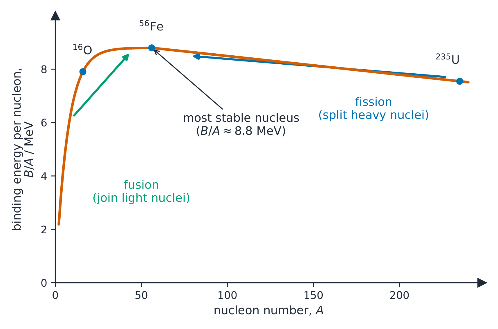
Syllabus
EnglishLearning Objective 15.7.A: Describe the physical properties that constrain the behavior of interacting nuclei, subatomic particles, and nucleons.
- 15.7.A.1 The strong force is exerted at nuclear scales and dominates the interactions of nucleons (protons or neutrons).
- 15.7.A.2 Possible nuclear reactions are constrained by the law of conservation of nucleon number.
- 15.7.A.3 The behavior of the constituent particles of a nuclear reaction is constrained by laws of conservation of energy, energy-mass equivalence, and conservation of momentum.
- 15.7.A.4 For all nuclear reactions, mass and energy may be exchanged due to mass-energy equivalence.
- Relevant equation:
- $E = mc^2$
- 15.7.A.5 Energy may be released in nuclear processes in the form of kinetic energy of the products or as photons.
- 15.7.A.6 Nuclear fusion is the process by which two or more smaller nuclei combine to form a larger nucleus, as well as subatomic particles.
- 15.7.A.7 Nuclear fission is the process by which the nucleus of an atom splits into two or more smaller nuclei, as well as subatomic particles.
- 15.7.A.8 Nuclear fission may occur spontaneously or may require an energy input, depending on the binding energy of the nucleus.
Learning Objective 15.7.B: Describe the radioactive decay of a given sample of material consisting of a finite number of nuclei.
- 15.7.B.1 Radioactive decay is the spontaneous transformation of a nucleus into one or more different nuclei.
- 15.7.B.1.i The time at which an individual nucleus undergoes radioactive decay is indeterminable, but decay rates can be described using probability
- 15.7.B.1.ii The half-life, $t_{1/2}$, of a radioactive material is the time it takes for half of the initial number of radioactive nuclei to have spontaneously decayed.
- 15.7.B.1.iii The decay constant $\lambda$ can be related to the half-life of a radioactive material with the equation $\lambda = \dfrac{\ln 2}{t_{1/2}}$.
- 15.7.B.2 A material's decay constant may be used to predict the number of nuclei remaining in a sample after a period of time, or the age of a material if the initial amount of material is known.
- Relevant equation:
- $N = N_0 e^{-\lambda t}$
- Derived equation:
- $\ln\left(\dfrac{N}{N_0}\right) = -\lambda t$
- 15.7.B.3 Different unstable elements and isotopes may have vastly different half-lives, ranging from fractions of a second to billions of years.
한국어학습 목표 15.7.A: 상호작용하는 원핵, 아원자 입자 및 핵자(양성자 또는 중성자)의 거동을 제한하는 물리적 성질을 설명한다.
- 15.7.A.1 강력은 핵 크기スケール에서 작용하며 핵자(양성자 또는 중성자) 간의 상호작용을 지배한다.
- 15.7.A.2 가능한 핵반응은 핵자 수 보존 법칙에 의해 제한된다.
- 15.7.A.3 핵반응을 구성하는 입자의 거동은 에너지 보존 법칙, 질량-에너지 등가성, 그리고 운동량 보존 법칙에 의해 제한된다.
- 15.7.A.4 모든 핵반응에서 질량-에너지 등가성에 의해 질량과 에너지가 교환될 수 있다.
- 관련 공식:
- $E = mc^2$
- 15.7.A.5 핵반응에서 에너지는 생성물의 운동에너지 형태로 방출되거나光子(photon) 형태로 방출될 수 있다.
- 15.7.A.6 핵융합은 두 개 이상의 작은 핵이 결합하여 더 큰 핵과 아원자 입자를 형성하는 과정이다.
- 15.7.A.7 핵분열은 한 원자의 핵이 두 개 이상의 작은 핵과 아원자 입자로 나뉘는 과정이다.
- 15.7.A.8 핵분열은 핵의 결합에너지에 따라 자발적으로 일어나거나 에너지 입력이 필요할 수 있다.
학습 목표 15.7.B: 유한한 수의 핵으로 구성된 특정 시료의 방사성 붕괴를 설명한다.
- 15.7.B.1 방사성 붕괴는 원자핵이 하나 이상의 다른 원자핵으로 자발적으로 변하는 과정입니다.
- 15.7.B.1.i 개별 원자핵이 방사성 붕괴를 일으키는 시점은 예측할 수 없지만, 붕괴율은 확률로 설명할 수 있습니다.
- 15.7.B.1.ii 방사성 물질의 반감기 $t_{1/2}$는 초기 방사성 원자핵의 절반이 자발적으로 붕괴하는 데 걸리는 시간입니다.
- 15.7.B.1.iii 붕괴 상수 $\lambda$는 방정식 $\lambda = \dfrac{\ln 2}{t_{1/2}}$을 통해 방사성 물질의 반감기와 관련될 수 있습니다.
- 15.7.B.2 물질의 붕괴 상수는 특정 기간 후 시료에 남아 있는 원자핵의 수를 예측하거나, 초기 물질량이 알려져 있을 때 물질의 나이를 추정하는 데 사용할 수 있습니다.
- 관련 공식:
- $N = N_0 e^{-\lambda t}$
- 유도 공식:
- $\ln\left(\dfrac{N}{N_0}\right) = -\lambda t$
- 15.7.B.3 서로 다른 불안정한 원소와 동위 원소는 초당 몇 분의 일초에서 수십억 년에 이르기까지 매우 다양한 반감기를 가질 수 있습니다.
Source: College Board AP Course and Exam Description · 출처: College Board AP Course and Exam Description
The nucleus 原子核 stores enormous energy. Fission 裂变 splits a heavy nucleus into lighter ones, releasing energy (nuclear reactors, bombs). Fusion 聚变 joins light nuclei into a heavier one (the Sun's power). Both release energy because the products have slightly less mass, converted by $E=mc^2$.
Binding energy per nucleon peaks near iron, so both fusion and fission can release energy Worked example. Even a tiny mass converts to a huge energy. If a nuclear reaction loses $1.0\times10^{-3}\ \text{kg}$ of mass, it releases $E=mc^2=1.0\times10^{-3}\times(3.0\times10^{8})^2=9.0\times10^{13}\ \text{J}$ – roughly the energy of $20\,000$ tonnes of TNT.
A nuclear power station: fission of heavy nuclei releases the energy that drives the plant Explore · 탐색하기Balance a nuclear decay equation · 핵 붕괴 반응식 균형 맞추기
In alpha, beta and gamma decay, nucleon and charge numbers must balance. Pick a mode and see how the parent turns into the daughter nuclide. · 알파(alpha), 베(beta), 감마(gamma) 붕괴에서 핵자 수와 전하 수는 반드시 균형을 이루어야 합니다. 괴 모드를 선택하여 원자핵(parent nuclide)이 자식 핵(daughter nuclide)으로 변하는 과정을 확인하세요.
Vocabulary · 어휘 Train · 연습하기English 한국어 nucleus/ˈnjuːklɪəs/ 핵 Fission/ˈfɪʃn/ Fission(核裂变) Fusion/ˈfjuːʒn/ Fusion(核聚变) 15.8
Types of Radioactive Decay
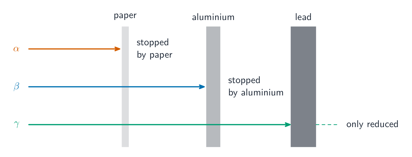
Syllabus
EnglishLearning Objective 15.8.A: Describe the processes by which individual nuclei decay.
- 15.8.A.1 Some processes by which nuclei decay emit subatomic particles with unique properties.
- 15.8.A.1.i An alpha particle, or helium nucleus, consists of two neutrons and two protons and is symbolized by $\alpha$ or $\text{He}^{2+}$. (In Physics 2, only He-4 nuclei will be considered.)
- 15.8.A.1.ii Neutrinos and antineutrinos are subatomic particles that have no electrical charge, have negligible mass, and are symbolized by $\nu$ and $\bar{\nu}$, respectively.
- 15.8.A.1.iii Neutrinos and antineutrinos only interact with matter via the weak force and the gravitational force, which results in very little interaction with normal matter.
- 15.8.A.1.iv Positrons, or antielectrons, are subatomic particles that have an electric charge opposite that of an electron, have the same mass as an electron, and are symbolized by $e^+$ or $\beta^+$.
- 15.8.A.2 Nuclei can undergo radioactive decay via alpha decay, beta-minus decay ($\beta^-$), beta-plus decay ($\beta^+$), and gamma decay ($\gamma$).
- 15.8.A.2.i In all nuclear decays, nucleon number (the number of neutrons and protons), lepton number (the number of electrons and neutrinos), and charge are conserved.
- 15.8.A.2.ii Alpha decay occurs when a nucleus ejects an alpha particle.
- 15.8.A.2.iii Beta-minus decay occurs when a neutron changes to a proton by emitting an electron and antineutrino.
- 15.8.A.2.iv Beta-plus decay occurs when a proton changes to a neutron by emitting a positron and neutrino.
- 15.8.A.2.v Gamma decay occurs after a nucleus has undergone alpha or beta decay and the excited nucleus decays to a lower energy state by emitting a photon.
- 15.8.A.3 The type of decay exhibited by a given nucleus is determined by the isotope of the element.
Boundary statement: AP Physics 2 does not expect students to memorize the processes by which specific isotopes decay or the half-lives of specific isotopes. Neutron emission and electron capture are not included in the AP Physics 2 curriculum framework. Additionally, types of neutrinos, the characteristics that distinguish neutrinos and antineutrinos, and an explanation or application of the weak force are not within the scope of this course.
한국어학습 목표 15.8.A: 개별 원자핵이 붕괴하는 과정을 설명합니다.
- 15.8.A.1 일부 핵 붕괴 과정은 고유한 특성을 가진 아원자 입자를 방출합니다.
- 15.8.A.1.i 알파 입자 또는 헬륨 원자핵은 중성자 2개와 양성자 2개로 구성되며, 기호는 $\alpha$ 또는 $\text{He}^{2+}$입니다. (물리학 2에서는 He-4 원자핵만 고려됩니다.)
- 15.8.A.1.ii 중미자 및 반중미자는 전기적 전하가 없고 질량이 거의 없는 아원자 입자로, 각각 기호는 $\nu$과 $\bar{\nu}$입니다.
- 15.8.A.1.iii 중미자와 반중미자는 약력 및 중력만을 통해 물질과 상호작용하므로 일반 물질과의 상호작용은 매우 적습니다.
- 15.8.A.1.iv 포지트론(반전자)은 전자와 반대 방향의 전기적 전하를 가지며, 전자와 동일한 질량을 가진 아원자 입자로, 기호는 $e^+$ 또는 $\beta^+$입니다.
- 15.8.A.2 원핵은 알파 붕괴, 베타-마이너스 붕괴($\beta^-$), 베타-플러스 붕괴($\beta^+$), 감마 붕괴($\gamma$)를 통해 방사성 붕괴를 일으킬 수 있다.
- 15.8.A.2.i 모든 핵 붕괴 과정에서 핵자 수(중성자와 양성자의 총수), 레프톤 수(전자와 중미자의 총수) 및 전하량은 보존됩니다.
- 15.8.A.2.ii 알파 붕괴는 원자핵이 알파 입자를 방출할 때 발생합니다.
- 15.8.A.2.iii 베타 마이너스 붕괴는 중성자가 전자와 반중미자를 방출하면서 양성자로 변환될 때 발생합니다.
- 15.8.A.2.iv 베타 플러스 붕괴는 양성자가 포지트론과 중미자를 방출하면서 중성자로 변환될 때 발생합니다.
- 15.8.A.2.v 감마 붕괴는 원자핵이 알파 붕괴나 베타 붕괴를 거친 후, 여기된 원자핵이 광자를 방출하여 낮은 에너지 상태로 붕괴할 때 발생합니다.
- 15.8.A.3 특정 원핵이 나타내는 붕괴의 유형은 해당 원소의 동위원소에 의해 결정된다.
범위 문장: AP 물리학 2에서는 특정 동위원소가 붕괴하는 과정이나 특정 동위원체의 반감기를 암기할 것을 기대하지 않는다. 중성자 방출 및 전자 포획은 AP 물리학 2 교육 과정 범위에 포함되지 않는다. 또한, 중성미자의 종류, 중성미자와 반중성미자를 구분하는 특성, 약력(weak force)에 대한 설명 또는 적용도 이 과목의 범위를 벗어난다.
Source: College Board AP Course and Exam Description · 출처: College Board AP Course and Exam Description
Radioactive decay & half-life Unstable nuclei undergo radioactive decay 放射性衰变, emitting:
The penetrating power of alpha, beta, and gamma radiation - Alpha decay 阿尔法衰变 ($\alpha$): a helium nucleus – mass number drops by 4.
- Beta decay 贝塔衰变 ($\beta$) comes in two kinds. In beta-minus ($\beta^-$) a neutron becomes a proton, emitting an electron and an antineutrino 反中微子: $n\rightarrow p+e^-+\bar{\nu}$. In beta-plus ($\beta^+$) a proton becomes a neutron, emitting a positron 正电子 and a neutrino 中微子: $p\rightarrow n+e^++\nu$.
- Gamma decay 伽马衰变 ($\gamma$): a high-energy photon – the nucleus sheds excess energy.
The neutrino and antineutrino (symbols $\nu$, $\bar{\nu}$) are tiny, chargeless, almost-massless particles that carry off energy and keep beta decay balanced. Decay is random, but a sample halves every half-life 半衰期: after each half-life, half of the remaining nuclei have decayed. Every decay equation conserves three quantities: nucleon number (mass number), charge, and lepton number 轻子数 – an electron or neutrino counts as $+1$ lepton, a positron or antineutrino as $-1$, and the totals must match on both sides.
Worked example. A radioactive sample has a half-life of $8.0$ days. What fraction is left after $24$ days? That is $24/8.0=3$ half-lives, so the fraction remaining is $\left(\tfrac12\right)^3=\tfrac18$ – about $12.5\%$. In an alpha decay of uranium-238 ($^{238}_{\ 92}\text{U}$), the daughter has mass number $238-4=234$ and atomic number $92-2=90$: thorium-234.
Explore · 탐색하기Watch a sample decay · 시료의 붕괴 과정 관찰하기
Radioactive nuclei decay randomly with a fixed half-life: each half-life halves the number remaining. Step forward and watch the sample shrink. · 방사성 핵은 일정한 **반감기(half-life)**를 따라 랜덤하게 붕괴합니다. 반감기가 지날 때마다 남은 수는 절반으로 줄어드는데, 시간을(stmt forward) 진행하며 시료가 shrinking하는 것을 보세요.
Vocabulary · 어휘 Train · 연습하기English 한국어 radioactive decay/ˌreɪdɪəʊˈæktɪv dɪˈkeɪ/ 방사성 붕괴 Alpha decay/ˈælfə dɪˈkeɪ/ 알파 붕괴 Beta decay/ˈbiːtə dɪˈkeɪ/ 베타 붕괴 antineutrino/ˌæntɪnjuːˈtriːnəʊ/ 반중성미자 positron/ˈpɒzɪtrɒn/ 양성자 neutrino/njuːˈtriːnəʊ/ 중성미자 Gamma decay/ˈɡæmə dɪˈkeɪ/ 감마 붕괴 half-life/hɑːf laɪf/ 반감기 lepton number/ˈleptɒn ˈnʌmbə/ เลป톤 수 15.8
Exam tips
- Photon energy is $E=hf$; below the threshold frequency no electrons are emitted however bright the light (the photoelectric effect).
- Use $K_{\max}=hf-\phi$ for the fastest photoelectrons ($\phi$ = work function).
- Electrons jump between discrete energy levels by absorbing/emitting a photon whose energy equals the level gap — the source of line spectra.
- In fission and fusion the small mass lost becomes energy via $E=mc^2$.
- Balance decay equations by conserving mass number, charge, and lepton number (write the antineutrino in $\beta^-$, the neutrino in $\beta^+$), and halve the sample every half-life ($(\tfrac12)^n$ after $n$ half-lives).
- 15.1.A.1 Quantum theory was developed to explain observations of matter and energy that could not be explained using classical mechanics. These phenomena include, but are not limited to, atomic spectra, blackbody radiation, and the photoelectric effect.