Skip to content

Geometric Optics

AP Physics 2 · Topic 13

Train
13.1

Reflection

Syllabus
Learning ObjectiveEssential Knowledge

13.1.A
Describe light as a ray.

  • 13.1.A.1 A light ray is a straight line that is perpendicular to the wavefront of a light wave and points in the direction of travel of the wave.
    • 13.1.A.1.i Light rays can be used to determine the behavior of light in geometric optics, where the wave nature of light can be neglected.
    • 13.1.A.1.ii Rays are not sufficient to understand the spreading of light. In interference and diffraction, the wave nature of the light is important.
    • 13.1.A.1.iii A laser is a common source of a single coherent, monochromatic beam of light that can be modeled as a ray. The wave nature of lasers will be considered in Unit 14.
  • 13.1.A.2 Ray diagrams depict the path of light before and after an interaction with matter.

13.1.B
Describe the reflection of light from a surface.

  • 13.1.B.1 Light that is incident on a surface can be reflected.
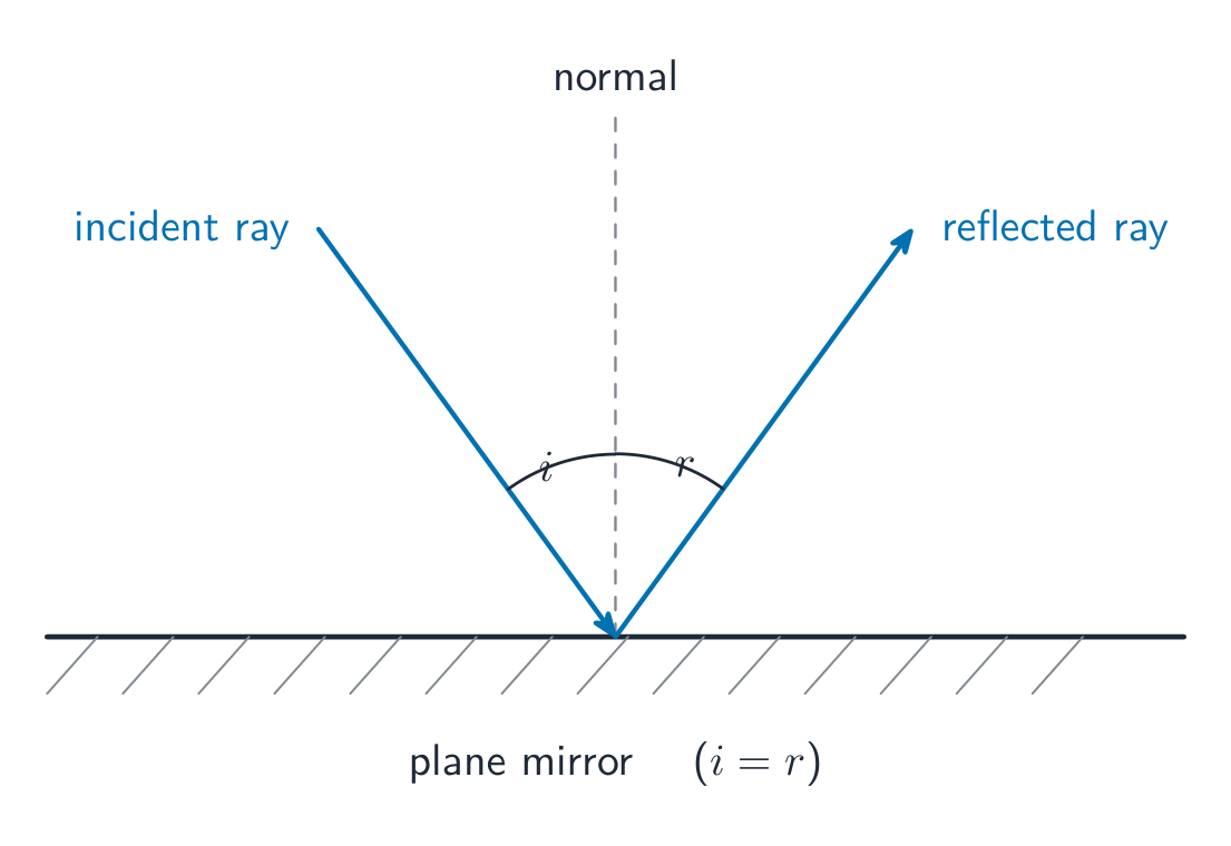
  • 13.1.B.2 The law of reflection states that the angle between the incident ray and the normal (the line perpendicular to the surface) is equal to the angle between the reflected ray and the normal.
    • Equation: $\theta_i = \theta_r$
  • 13.1.B.3 Diffuse reflection is the reflection of light from a rough surface and results in light reflected in many different directions, because the line normal to the surface varies over the area over which the light is incident.
  • 13.1.B.4 Specular reflection is the reflection of light from a smooth surface and results in light uniformly reflected from the surface, because the line normal to the surface has an approximately constant direction over the area the light strikes.

Source: College Board AP Course and Exam Description

Geometric optics 几何光学 treats light as straight-line rays. The law of reflection 反射定律: when light bounces off a surface, the angle of incidence 入射角 equals the angle of reflection 反射角, both measured from the normal (the line perpendicular to the surface). Smooth surfaces reflect a clear image; rough surfaces scatter the rays.

The law of reflection: the angle of incidence equals the angle of reflection The law of reflection: the angle of incidence equals the angle of reflection

Vocabulary Train
English Chinese Pinyin
Geometric optics 几何光学 jǐ hé guāng xué
law of reflection 反射定律 fǎn shè dìng lǜ
angle of incidence 入射角 rù shè jiǎo
angle of reflection 反射角 fǎn shè jiǎo
13.2

Images Formed by Mirrors

Syllabus
Learning ObjectiveEssential Knowledge

13.2.A
Describe the image formed by a mirror.

  • 13.2.A.1 Incident light rays parallel to the principal axis of a concave (converging) mirror will be reflected toward a common location, called the focal point.
  • 13.2.A.2 Incident light rays parallel to the principal axis of a convex (diverging) mirror will be reflected such that they appear to have originated from a common location behind the mirror, called the focal point.
  • 13.2.A.3 The focal point of a plane mirror is an infinite distance from the mirror.
  • 13.2.A.4 The focal point of a spherical mirror may be approximated as a point located on the principal axis of the mirror halfway between the surface of the mirror and the center of the mirror's radius of curvature.
  • 13.2.A.5 A real image is formed by a mirror when light rays emanating from a common point are reflected and then intersect at a common point.
  • 13.2.A.6 A virtual image is formed by a mirror when reflected light rays diverge such that they appear to have originated from a common point.
  • 13.2.A.7 The location of an image depends on the focal length of the mirror and the distance between the object and the surface of the mirror.
    • Equation: $\dfrac{1}{s_i} + \dfrac{1}{s_o} = \dfrac{1}{f}$
    • 13.2.A.7.i The locations of a mirror's focal point, an object near the mirror, and the image of the object formed by the mirror follow sign conventions that are used to determine those locations relative to the mirror itself.
    • 13.2.A.7.ii The distance between the image formed and a plane mirror is equal to the distance between the object and the plane mirror.
  • 13.2.A.8 The magnification of an image formed by a mirror is the ratio of the size of the image produced to the size of the object itself and depends on the locations of the object and image relative to the mirror.
    • Equation: $|M| = \left| \dfrac{h_i}{h_o} \right| = \left| \dfrac{s_i}{s_o} \right|$
  • 13.2.A.9 Ray diagrams can be used to determine the location, type, size, and orientation of images formed by mirrors.
    • 13.2.A.9.i The three principal rays are typically used to find the images formed by mirrors. The principal rays are 1) the ray parallel to the principal axis, 2) the ray that reflects at the center of the mirror where the principal axis intersects the mirror, and 3) the ray that passes through the focal point of the mirror.
    • 13.2.A.9.ii Images formed by a mirror can be upright or inverted, virtual or real, and reduced, enlarged, or the same size as the object.

Boundary statement: AP Physics 2 limits the study of mirrors to plane mirrors, convex spherical mirrors, and concave spherical mirrors.

Source: College Board AP Course and Exam Description

A curved mirror focuses parallel rays at its focal point, a distance $f$ from the mirror. The mirror equation relates object and image distances:

$$\frac{1}{d_o}+\frac{1}{d_i}=\frac{1}{f},\qquad m=-\frac{d_i}{d_o}.$$
A concave mirror 凹面镜 (converging) can form a real image 实像 (rays actually meet, projectable, inverted); a convex mirror 凸面镜 always forms a virtual image 虚像 (rays only appear to meet, upright, reduced). The magnification $m$ gives the image's size and orientation. Sign convention matters: a negative image distance means a virtual image behind the mirror or lens.

Explore

Form an image with a curved mirror

A concave mirror reflects rays through its focus. The object's distance relative to the focal length decides whether the image is real or virtual, enlarged or reduced.

Vocabulary Train
English Chinese Pinyin
concave mirror 凹面镜 āo miàn jìng
real image 实像 shí xiàng
convex mirror 凸面镜 tū miàn jìng
virtual image 虚像 xū xiàng
13.3

Refraction

Syllabus
Learning ObjectiveEssential Knowledge

13.3.A
Describe the refraction of light between two media.

  • 13.3.A.1 Refraction is the change in direction of a light ray as the ray passes from one medium into another.
  • 13.3.A.2 Refraction is a result of the speed of light changing when light enters a new medium.
  • 13.3.A.3 The index of refraction of a given medium is inversely proportional to the speed of light in the medium.
    • Equation: $n = \dfrac{c}{v}$
  • 13.3.A.4 Snell's law relates the angles of incidence and refraction of a light ray passing from one medium into another to the indices of refraction of the two media.
    • Equation: $n_1 \sin\theta_1 = n_2 \sin\theta_2$
    • 13.3.A.4.i When a light ray travels from a medium with a higher index of refraction into a medium with a lower index of refraction, the ray refracts away from the normal.
    • 13.3.A.4.ii When a light ray travels from a medium with a lower index of refraction into a medium with a higher index of refraction, the ray refracts toward the normal.
    • 13.3.A.4.iii When a light ray is incident along the normal to a surface, the transmitted ray is not refracted.
  • 13.3.A.5 Total internal reflection may occur when light passes from one medium into another medium with a lower index of refraction.
    • 13.3.A.5.i Total internal reflection of light occurs beyond a critical angle of incidence.
      • Derived equation: $\theta_{\text{critical}} = \sin^{-1}\left( \dfrac{n_2}{n_1} \right)$
    • 13.3.A.5.ii For incident rays at the critical angle, the ray refracts at 90 degrees and travels along the surface of the material.
    • 13.3.A.5.iii For incident rays beyond the critical angle, all light is reflected (no light is transmitted into the other medium).

Source: College Board AP Course and Exam Description

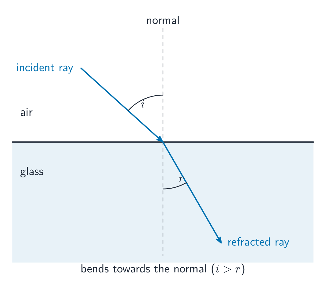
Light bends when it passes between materials because its speed changes – refraction 折射. Each material has an index of refraction 折射率 $n=\dfrac{c}{v}$ (how much it slows light). Snell's law 斯涅尔定律:

$$n_1\sin\theta_1=n_2\sin\theta_2.$$
Light entering a denser medium (larger $n$) bends toward the normal. Beyond a critical angle, light going to a less-dense medium reflects entirely – total internal reflection 全反射, used in fibre optics.

Light refracts, bending towards the normal as it enters glass Light refracts, bending towards the normal as it enters glass

Worked example. A ray in air ($n_1=1.00$) strikes water ($n_2=1.33$) at $40^{\circ}$ to the normal. By Snell's law,

$$\sin\theta_2=\frac{n_1}{n_2}\sin\theta_1=\frac{1.00}{1.33}\sin 40^{\circ}=0.483\;\Rightarrow\;\theta_2=29^{\circ}.$$
The ray bends toward the normal, as expected going into the denser medium.

Worked example (critical angle). For light trying to leave glass ($n=1.50$) for air, total internal reflection begins at the critical angle $\theta_c$ where the refracted ray grazes the surface:

$$\sin\theta_c=\frac{1}{n}=\frac{1}{1.50}=0.667\;\Rightarrow\;\theta_c=42^{\circ}.$$
Any ray hitting the inside surface more steeply than $42^{\circ}$ is trapped – the reason optical fibres carry light for kilometres.
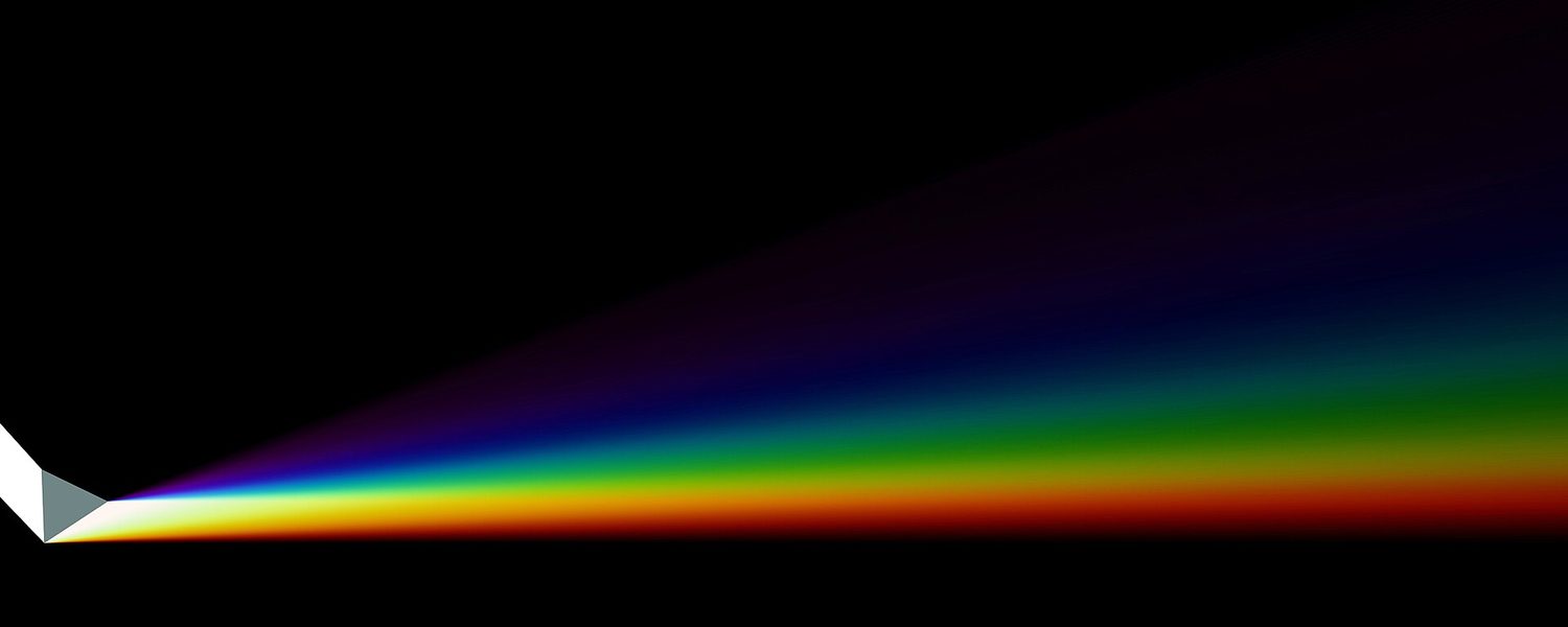
White light splitting into a spectrum through a glass prism Refraction bends each colour by a different amount, so a prism spreads white light into a rainbow

Explore

Bend light as it enters glass

Light refracts (bends) when it changes speed between media, following Snell's law. The denser the medium, the more it bends toward the normal.

Vocabulary Train
English Chinese Pinyin
refraction 折射 zhé shè
index of refraction 折射率 zhé shè lǜ
Snell's law 斯涅尔定律 sī niè ěr dìng lǜ
total internal reflection 全反射 quán fǎn shè
13.4

Images Formed by Lenses

Syllabus
Learning ObjectiveEssential Knowledge

13.4.A
Describe the image formed by a lens.

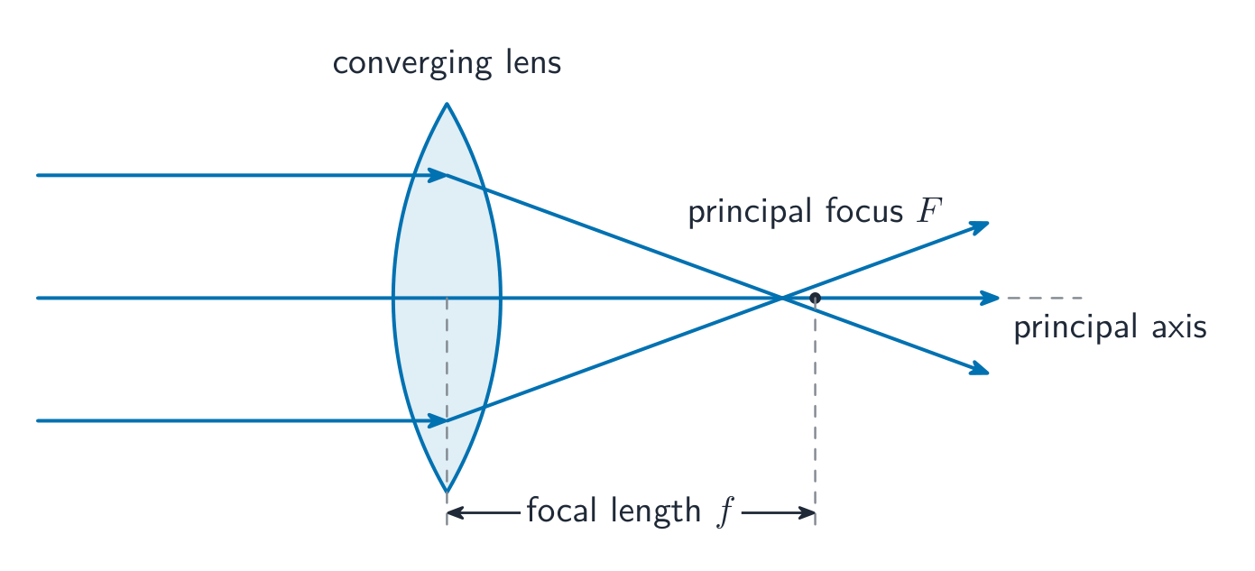
  • 13.4.A.1 Incident light rays parallel to the principal axis of a thin convex (converging) lens will be refracted and converge toward a common location on the transmitted side of the lens, called the focal point.
  • 13.4.A.2 Incident light rays parallel to the principal axis of a thin concave (diverging) lens will be refracted and diverge as if they originated from a focal point on the incident side of the lens.
  • 13.4.A.3 A real image is formed by a lens when light rays originating from a common point are refracted such that they intersect at another common point.
  • 13.4.A.4 A virtual image is formed by a lens when refracted light rays diverge such that they appear to have originated from a common point.
  • 13.4.A.5 For a thin lens, the location of an image depends on the focal length of the lens and the distance between the object and the midline of the lens, as given by the thin-lens equation:
    • Equation: $\dfrac{1}{s_i} + \dfrac{1}{s_o} = \dfrac{1}{f}$
    • 13.4.A.5.i The locations of a lens's focal point, an object, and the image of the object formed by the lens follow sign conventions that are used to determine those locations relative to the lens itself.
    • 13.4.A.5.ii Lenses have a focal point on both sides of the lens that depends on the shape of the respective side of the lens.
  • 13.4.A.6 For a thin lens, the magnification of an image is the ratio of the size of the image produced to the size of the object itself and depends on the locations of the object and image relative to the lens.
    • Equation: $|M| = \left| \dfrac{h_i}{h_o} \right| = \left| \dfrac{s_i}{s_o} \right|$
  • 13.4.A.7 Ray diagrams can be used to determine the location, type, size, and orientation of images formed by lenses.
    • 13.4.A.7.i The three principal rays are typically used to find the images formed by lenses. The principal rays are 1) the ray parallel to the principal axis, 2) the ray that passes through the center of the lens where the principal axis intersects the lens, and 3) the ray that passes through the focal point of the lens.
    • 13.4.A.7.ii Images formed by a lens can be upright or inverted, virtual or real, and reduced, enlarged, or the same size as the object.

Source: College Board AP Course and Exam Description

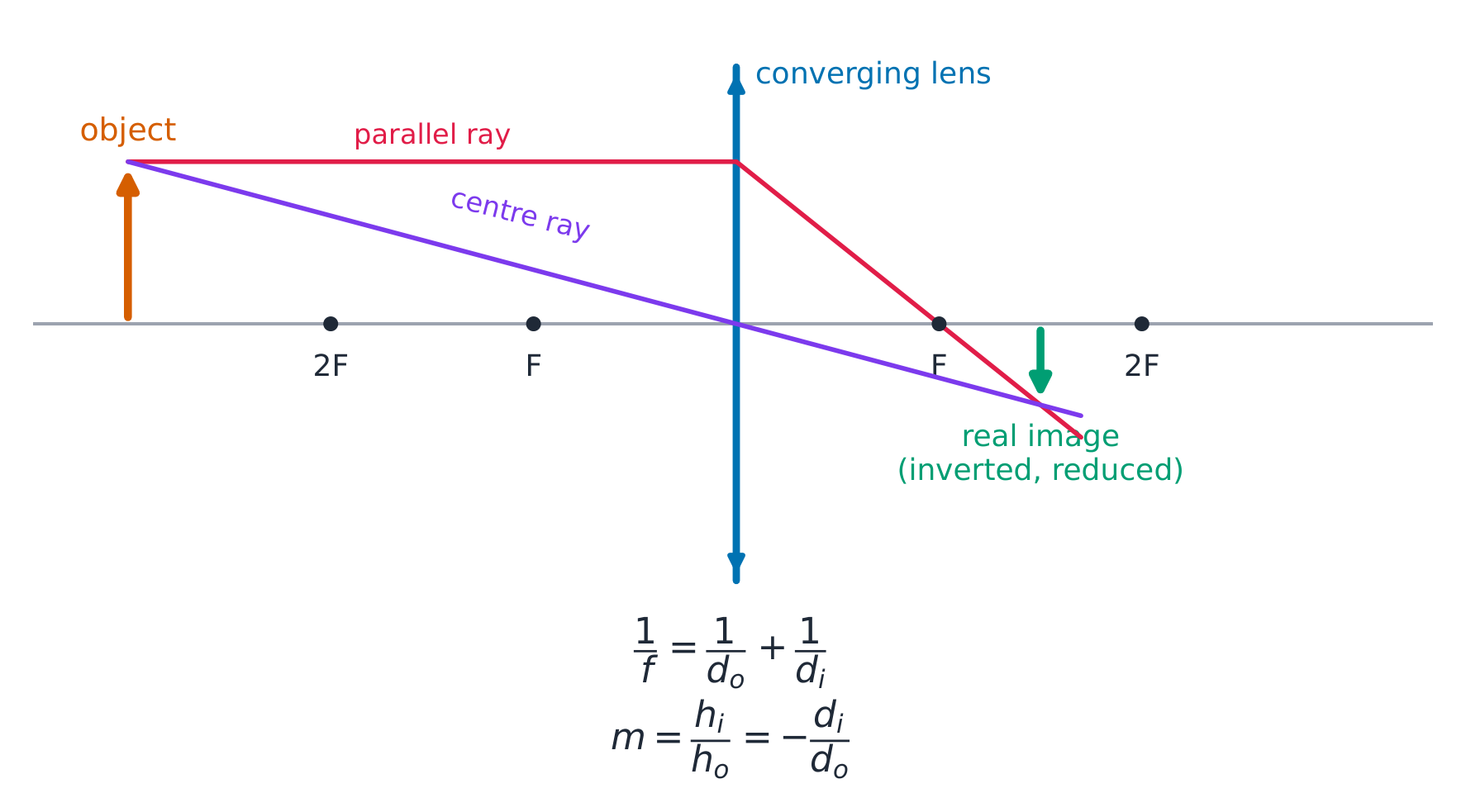
A converging lens forms a real image

A lens bends light through refraction. The thin-lens equation has the same form as the mirror equation:

$$\frac{1}{d_o}+\frac{1}{d_i}=\frac{1}{f},\qquad m=-\frac{d_i}{d_o}.$$
A converging 会聚 (convex) lens can form a real, inverted image or, for a close object, a virtual, upright, enlarged image (a magnifying glass). A diverging 发散 (concave) lens always forms a virtual, upright, reduced image. Ray diagrams locate the image quickly using two easy rays: one parallel to the axis that bends to pass through the far focus, and one straight through the centre of the lens (undeviated).
Two rays locate the image: parallel-then-focus, and straight through the centre Two rays locate the image: parallel-then-focus, and straight through the centre

A converging lens brings parallel rays to its principal focus A converging lens brings parallel rays to its principal focus

Worked example. An object sits $30\ \text{cm}$ from a converging lens of focal length $f=10\ \text{cm}$. Find the image. From the thin-lens equation,

$$\frac{1}{d_i}=\frac{1}{f}-\frac{1}{d_o}=\frac{1}{10}-\frac{1}{30}=\frac{2}{30}\;\Rightarrow\;d_i=15\ \text{cm},$$
and the magnification is $m=-d_i/d_o=-15/30=-0.5$. The image is real (positive $d_i$), inverted (negative $m$), and half the object's size – just what a camera lens does.
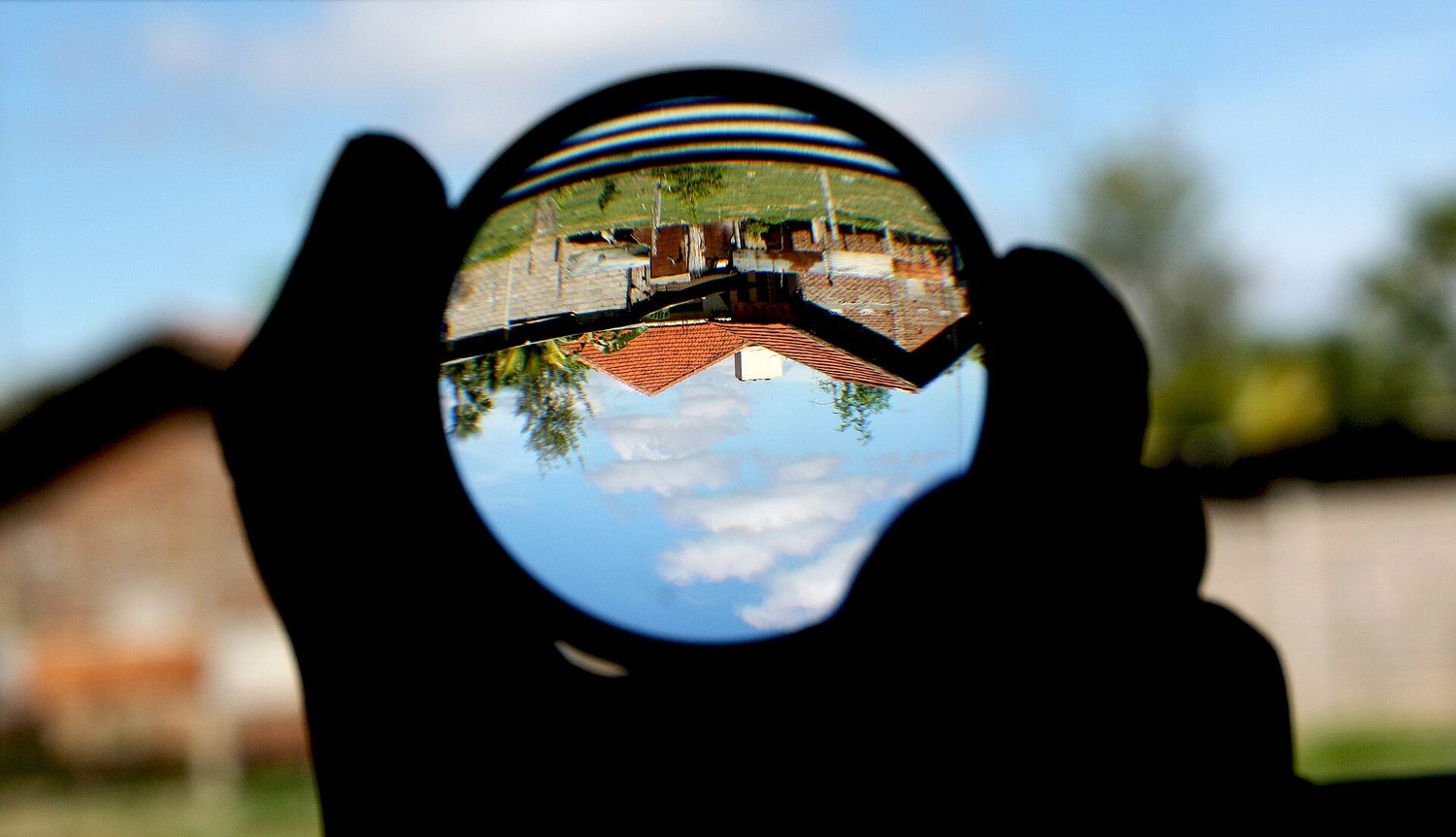
A magnifying glass showing an upside-down image behind it A convex lens forms a real, inverted image of a distant scene, exactly as the ray diagram predicts

Explore

Form an image with a converging lens

A converging lens bends parallel rays to its focal point. Move the object and watch the image change from large and inverted to virtual and upright inside the focal length.

Vocabulary Train
English Chinese Pinyin
converging 会聚 huì jù
diverging 发散 fā sàn
Exercise sheet
13.4

Exam tips

  • Measure all angles from the normal, not the surface.
  • Light entering a denser medium (larger $n$) bends toward the normal; use Snell's law $n_1\sin\theta_1=n_2\sin\theta_2$.
  • Total internal reflection happens only going into a less dense medium, beyond the critical angle ($\sin\theta_c=1/n$).
  • For mirrors and lenses use $\tfrac1{d_o}+\tfrac1{d_i}=\tfrac1f$ and $m=-d_i/d_o$: a positive $d_i$ is a real image, negative is virtual.
  • $n=c/v$, so a bigger index means a slower speed of light in the material.

Log in or create account

IGCSE & A-Level