Skip to content · ⁨コンテンツへスキップ⁩

Electric Circuits

AP Physics 2 · ⁨AP物理学 2⁩ · Topic 11 · ⁨トピック 11⁩

View Slides · ⁨查看幻灯片⁩ Train · ⁨練習する⁩
Video lesson for this topic · ⁨このトピックのビデオレッスン⁩ Open the video page · ⁨動画ページを開く⁩
7:45

電気回路

スイッチをオンにすると、電灯が即座に点灯します。したがって電子はワイヤー内を疾走しているはずです。しかし実際にはそうではありません。銅の内部では、電子は這うように動きます — …未満の…

English narration · English + 中文 subtitles burned in · ⁨英語ナレーション・英語+中文字幕 burning-in⁩

11.1

Electric Current · ⁨電気伝導⁩

Syllabus · ⁨シラバス⁩
English

Learning Objective 11.1.A: Describe the movement of electric charges through a medium.

  • 11.1.A.1 Current is the rate at which charge passes through a cross-sectional area of a wire.
    • Equation: $I = \dfrac{\Delta q}{\Delta t}$
    • 11.1.A.1.i Electric charge moves in a circuit in response to an electric potential difference, sometimes referred to as electromotive force, or $\mathrm{emf}$ ($\varepsilon$).
    • 11.1.A.1.ii If the current is zero in a section of wire, the net motion of charge carriers in the wire is also zero, although individual charge carriers will not have zero speed.
  • 11.1.A.2 Although current is not a vector quantity, it does have a direction. The direction of current is associated with what the motion of positive charge would be but not with any coordinate system in space.
    • 11.1.A.2.i The direction of conventional current is chosen to be the direction in which positive charge would move.
    • 11.1.A.2.ii In common circuits, current is actually due to the movement of electrons (negative charge carriers).
日本語

学習目標 11.1.A: 電荷が媒質中を移動する様子について説明せよ。

  • 11.1.A.1 電流とは、電荷が導線の断面を通過する速さである。
    • 式: $I = \dfrac{\Delta q}{\Delta t}$
    • 11.1.A.1.i 回路内での電荷の移動は、電位差( sometimes referred to as electromotive force)に応じ、時折 $\mathrm{emf}$ ($\varepsilon$) と呼ばれるものによって引き起こされる。
    • 11.1.A.1.ii 導線のある部分で電流がゼロの場合、電荷運搬体の全体としての移動もゼロとなるが、個々の電荷運搬体の速度がゼロになるわけではない。
  • 11.1.A.2 電流はベクトル量ではないものの、方向を持つ。電流の方向は正の電荷が動いた方向に関連付けられるが、空間内の座標系には依存しない。
    • 11.1.A.2.i 慣用電流の方向は、正の電荷が動いた方向として選ばれる。
    • 11.1.A.2.ii 一般的な回路において、電流は実際には電子(負の電荷運搬体)の移動によるものである。
Source: College Board AP Course and Exam Description · ⁨出典: College Board AP コースおよび試験説明書⁩

English

Electric current 电流 is the rate at which charge flows past a point, measured in amperes 安培 (A):

$$I=\frac{\Delta q}{\Delta t}.$$
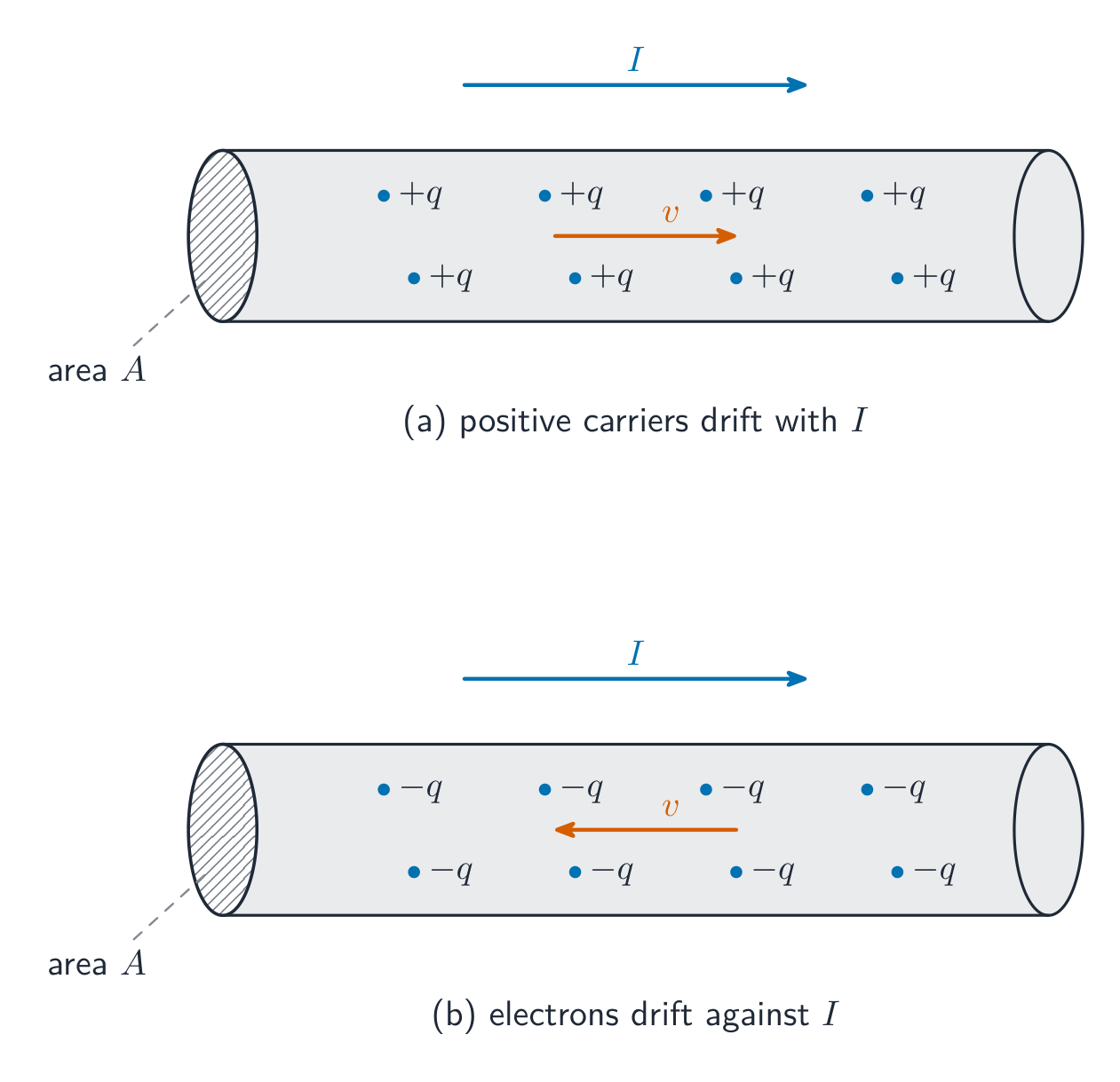
By convention, current points the way positive charge would move (opposite to the electrons in a wire). A steady current needs a complete loop and an energy source (a battery's electromotive force, or emf).

日本語
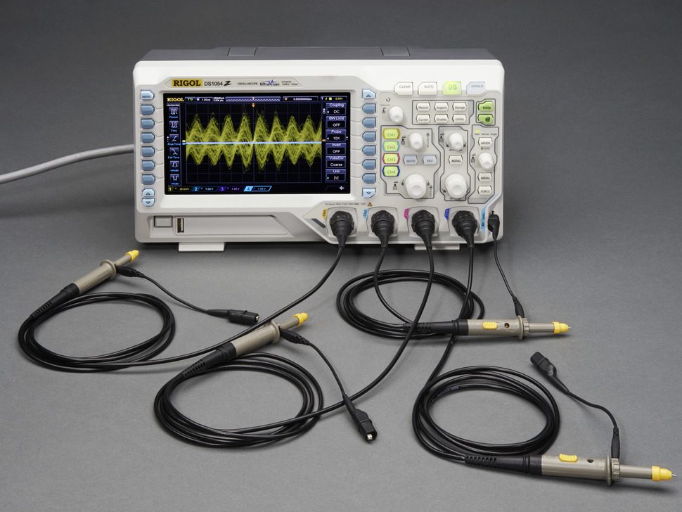
オシロスコープ:回路の時間的な挙動は、時間に対する電圧として測定される

電気伝導とは、一点を通過する電荷の流れの速さであり、アンペア (A) で測定されます:

$$I=\frac{\Delta q}{\Delta t}.$$
慣例として、伝導は正の電荷が動く方向を指します(導線内の電子とは逆向きです)。定常伝導には完全なループとエネルギー源(バッテリーの起電力、またはemf)が必要です。

伝導体中を電荷キャリアがゆっくりと漂移して伝導を作る
11.2

Simple Circuits · ⁨単純回路⁩

Syllabus · ⁨シラバス⁩
English

Learning Objective 11.2.A: Describe the behavior of a circuit.

  • 11.2.A.1 A circuit is composed of electrical loops, which may include circuit elements such as wires, batteries, resistors, lightbulbs, capacitors, switches, ammeters, and voltmeters.
  • 11.2.A.2 A closed electrical loop is a closed path through which charges may flow.
    • 11.2.A.2.i A closed circuit is one in which charges would be able to flow.
    • 11.2.A.2.ii An open circuit is one in which charges would not be able to flow.
    • 11.2.A.2.iii A short circuit is one in which charges would be able to flow with no change in potential difference.
  • 11.2.A.3 A single circuit element may be part of multiple electrical loops.
  • 11.2.A.4 Circuit schematics are representations used to describe and analyze electric circuits.
    • 11.2.A.4.i The properties of an electric circuit are dependent on the physical arrangement of its constituent elements.
    • 11.2.A.4.ii Circuit elements have common symbols that are used to create schematic diagrams. Variable elements are indicated by a diagonal strikethrough arrow across the standard symbol for that element. (Standard symbols: Battery, Bulb, Switch, Capacitor, Resistor, Ammeter, Voltmeter.)

Boundary statement: Unless otherwise specified, all circuit schematic diagrams will be drawn using conventional current.

日本語

学習目標 11.2.A: 回路の挙動を説明せよ。

  • 11.2.A.1 回路は、導線、電池、抵抗器、電球、コンデンサ、スイッチ、アンメーター、ボルトメーターなどの回路素子を含む電気ループから構成される。
  • 11.2.A.2 閉じた電気ループとは、電荷が流れることのできる閉じた経路である。
    • 11.2.A.2.i 閉回路とは、電荷が流れることのできる回路である。
    • 11.2.A.2.ii 開回路とは、電荷が流れることのできない回路である。
    • 11.2.A.2.iii 短絡回路とは、電位差の変化なしに電荷が流れることのできる回路である。
  • 11.2.A.3 単一の回路素子が複数の電気ループの一部となることがある。
  • 11.2.A.4 回路図式とは、電気回路を記述・解析するために用いられる表現である。
    • 11.2.A.4.i 電気回路の性質は、その構成素子の物理的な配置に依存する。
    • 11.2.A.4.ii 回路素子には、図式を作成するために用いられる共通の記号がある。可変素子は、その素子の標準記号に斜めのストライクスルー矢印で示される。(標準記号:電池、電球、スイッチ、コンデンサ、抵抗器、アンメーター、ボルトメーター。)

境界文: 特に指定がない限り、すべての回路図式は慣用電流を用いて描かれる。

Source: College Board AP Course and Exam Description · ⁨出典: College Board AP コースおよび試験説明書⁩

English

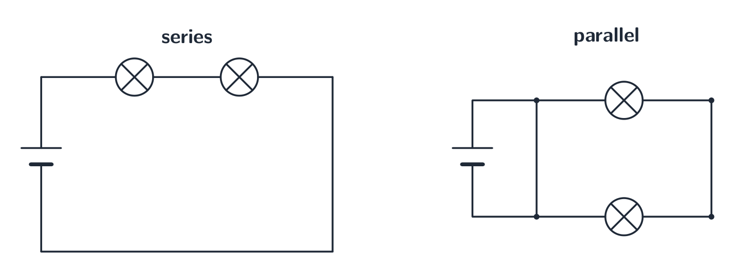
A circuit is a closed loop of conductors, a source (battery), and components. In a series 串联 path the same current flows through each element; in a parallel 并联 path the same voltage is across each branch. A circuit diagram uses standard symbols; reading it correctly is the first step of any circuit problem.

日本語

回路は、導体の閉じたループ、電源(バッテリー)、および素子の組み合わせです。直列接続では各素子を通る電流は同じであり、並列接続では各分岐にかかる電圧は同じです。回路図は標準記号を使用しており、それを正しく読むことはすべての回路問題における第一歩です。

素子は直列または並列に接続できる
素子は直列または並列に接続できる
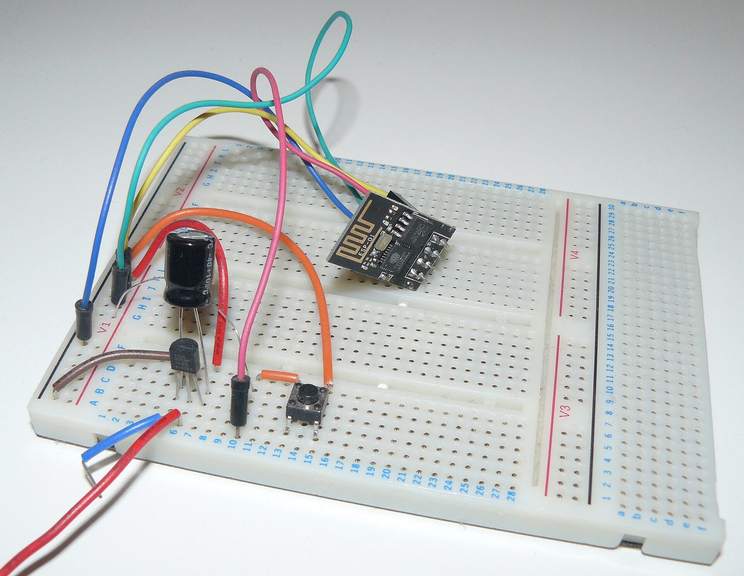
ブロードボード上に組み込まれた電子回路
実際の回路:素子をブロードボードに差し込み、ワイヤーで接続して伝導が完全に通る経路を作る
Explore · ⁨探索⁩

Build series and parallel circuits · ⁨直列・並列回路を組む⁩

In series the same current flows through every bulb and voltage divides; in parallel each branch gets the full voltage. Switch mode to see the bulbs' brightness change. · ⁨直列 では全ランプを通る電流は同じで電圧は分配され、並列 では各枝に全電圧がかかる。モードを変えてランプの明るさの変化を見る。⁩

Vocabulary · ⁨語彙⁩ Train · ⁨練習する⁩
English 日本語
Electric current/ɪˈlektrɪk ˈkʌrənt/ 電流
amperes/ˈæmpeəz/ アンペア
series/ˈsɪəriːz/ 直列に接続される
parallel/ˈpærəlel/ 並列に接続される
Resistance/rɪˈzɪstəns/ Resistance
Ohm's law/əʊmz lɔː/ オームの法則
resistivity/ˌriːzɪˈstɪvəti/ 比抵抗
Electric power/ɪˈlektrɪk ˈpaʊə/ 電力
light bulb/laɪt bʌlb/ 電球
brightness/ˈbraɪtnəs/ 明るさ
equivalent resistance/ɪˈkwɪvələnt rɪˈzɪstəns/ 等価抵抗
ammeter/ˈæmiːtə/ アンメーター
voltmeter/ˈvəʊltmiːtə/ ボルテメーター
nonideal/ˌnɒnaɪˈdɪəl/ 非理想
Kirchhoff's loop rule/ˈkɜːkhɒfs luːp ruːl/ キルヒホッフのループ則
Kirchhoff's junction rule/ˈkɜːkhɒfs ˈdʒʌŋkʃn ruːl/ キルヒホッフの接点則
RC circuit/ˌɑː ˈsiː ˈsɜːkɪt/ RC回路
11.3

Resistance, Resistivity, and Ohm's Law · ⁨抵抗、比抵抗、およびオームの法則⁩

Syllabus · ⁨シラバス⁩
English

Learning Objective 11.3.A: Describe the resistance of an object using physical properties of that object.

  • 11.3.A.1 Resistance is a measure of the degree to which an object opposes the movement of electric charge.
  • 11.3.A.2 The resistance of a resistor with uniform geometry is proportional to its resistivity and length and is inversely proportional to its cross-sectional area.
    • Equation: $R = \dfrac{\rho \ell}{A}$
    • 11.3.A.2.i Resistivity is a fundamental property of a material that depends on its atomic and molecular structure and quantifies how strongly the material opposes the motion of electric charge.
    • 11.3.A.2.ii The resistivity of a conductor typically increases with temperature.

Learning Objective 11.3.B: Describe the electrical characteristics of elements of a circuit.

  • 11.3.B.1 Ohm's law relates current, resistance, and potential difference across a conductive element of a circuit.
    • Equation: $I = \dfrac{\Delta V}{R}$
    • 11.3.B.1.i Materials that obey Ohm's law have constant resistance for all currents and are called ohmic materials.
    • 11.3.B.1.ii The resistivity of an ohmic material is constant regardless of temperature.
    • 11.3.B.1.iii Resistors can also convert electrical energy to thermal energy, which may change the temperature of both the resistor and the resistor's environment.
    • 11.3.B.1.iv The resistance of an ohmic circuit element can be determined from the slope of a graph of the current in the element as a function of the potential difference across the element.
日本語

学習目標 11.3.A: その物体の物理的性質を用いて、物体の抵抗を説明せよ。

  • 11.3.A.1 抵抗とは、物体が電荷の移動をどの程度阻止するかを示す指標である。
  • 11.3.A.2 均一な形状を持つ抵抗器の抵抗は、その比抵抗および長さに比例し、断面積に反比例する。
    • 式: $R = \dfrac{\rho \ell}{A}$
    • 11.3.A.2.i 比抵抗は、原子および分子構造に依存する材料の基本的な性質であり、材料が電荷の移動をどの程度強く阻止するかを定量化する。
    • 11.3.A.2.ii 導体の比抵抗は一般的に温度の上昇とともに増加する。

学習目標 11.3.B: 回路の素子の電気的特性を説明せよ。

  • 11.3.B.1 オームの法則は、回路の導電性素子における電流、抵抗、および電位差の関係を表す。
    • 式: $I = \dfrac{\Delta V}{R}$
    • 11.3.B.1.i オームの法則に従う材料は、すべての電流に対して一定の抵抗を持ち、オーム性材料と呼ばれる。
    • 11.3.B.1.ii オーム性材料の比抵抗は、温度に関わらず一定である。
    • 11.3.B.1.iii 抵抗器はまた、電気エネルギーを熱エネルギーに変換することができ、これにより抵抗器自体およびその環境の温度が変化する可能性がある。
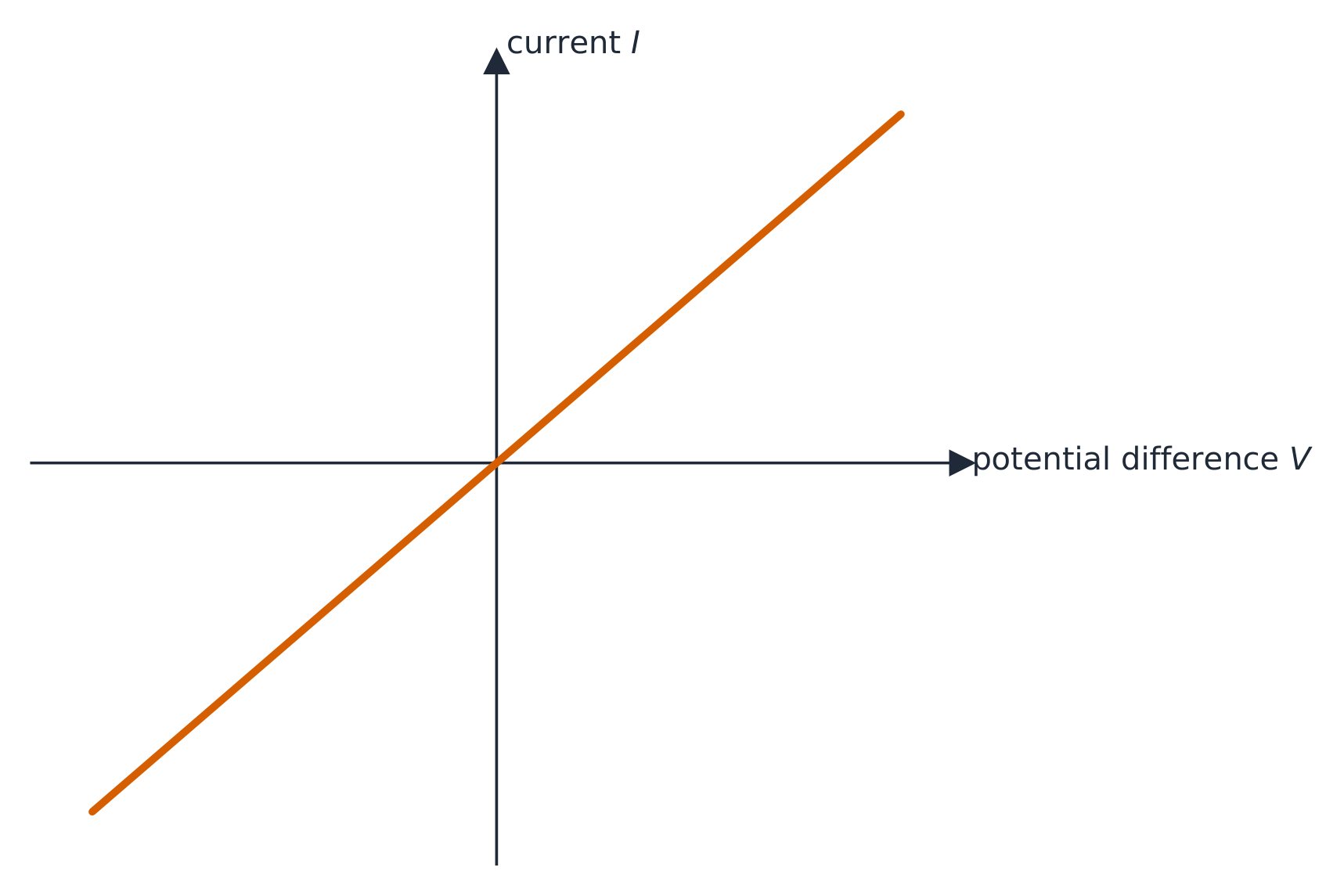
    • 11.3.B.1.iv オーム性回路素子の抵抗は、その素子にかかる電位差に対する素子内の電流のグラフの傾きから求めることができる。

Source: College Board AP Course and Exam Description · ⁨出典: College Board AP コースおよび試験説明書⁩

English

Resistance 电阻 $R$ opposes current, measured in ohms. Ohm's law 欧姆定律 links the three key quantities:

$$V=IR.$$
A component's resistance depends on the material's resistivity 电阻率 $\rho$, its length, and its cross-sectional area: $R=\dfrac{\rho L}{A}$ – longer and thinner means more resistance.

Worked example. A $2.0\ \text{A}$ current flows through a $6.0\ \Omega$ resistor. The voltage across it is $V=IR=2.0\times6.0=12\ \text{V}$.

日本語

抵抗 $R$ は伝導を妨げ、オームで測定されます。オームの法則は3つの主要な物理量を結びつけます:

$$V=IR.$$
素子の抵抗は、材料の比抵抗 $\rho$、長さ、および断面積に依存します:$R=\dfrac{\rho L}{A}$ – 長く細いほど抵抗が大きくなります。

オーム性導体のI-V曲線は原点を通る直線です

** worked example.** $2.0\ \text{A}$ の電流が $6.0\ \Omega$ の抵抗器を通ります。その両端の電圧は $V=IR=2.0\times6.0=12\ \text{V}$ です。

Explore · ⁨探索⁩

Apply Ohm's law · ⁨オームの法則を適用する⁩

Ohm's law $V=IR$: for a fixed resistance, current is proportional to voltage. Raise the resistance and the same voltage pushes less current. · ⁨オームの法則 $V=IR$:抵抗一定の場合、電流は電圧に比例する。抵抗を増やすと、同じ電圧でも流れる電流は減る。⁩

11.4

Electric Power · ⁨電気出力⁩

Syllabus · ⁨シラバス⁩
English

Learning Objective 11.4.A: Describe the transfer of energy into, out of, or within an electric circuit, in terms of power.

  • 11.4.A.1 The rate at which energy is transferred, converted, or dissipated by a circuit element depends on the current in the element and the electric potential difference across it.
    • Equation: $P = I \Delta V$
    • Equation (derived): $P = I^2 R = \dfrac{(\Delta V)^2}{R}$
  • 11.4.A.2 The brightness of a bulb increases with power, so power can be used to qualitatively predict the brightness of bulbs in a circuit.
日本語

学習目標 11.4.A: 電力を用いて、電気回路へのエネルギーの流入、流出、または内部移動を説明せよ。

  • 11.4.A.1 回路素子によってエネルギーが転移、変換、または散逸される速さは、その素子内の電流およびそれにかかる電位差に依存する。
    • 式: $P = I \Delta V$
    • 式(導出): $P = I^2 R = \dfrac{(\Delta V)^2}{R}$
  • 11.4.A.2 電球の明るさは電力に比例して増すため、回路内の電球の明るさを定性的に予測するために電力を用いることができる。

Source: College Board AP Course and Exam Description · ⁨出典: College Board AP コースおよび試験説明書⁩

English

Electric power 电功率 is the rate a component converts electrical energy (to heat, light, motion):

$$P=IV=I^2R=\frac{V^2}{R}.$$
Pick the form that uses the quantities you know. A resistor's power all becomes heat.

Worked example. The $6.0\ \Omega$ resistor above, carrying $2.0\ \text{A}$, dissipates $P=I^2R=2.0^2\times6.0=24\ \text{W}$ – equivalently $P=IV=2.0\times12=24\ \text{W}$.

A light bulb 灯泡 is just a resistor that glows, and its brightness 亮度 rises with the power it dissipates. So to rank bulbs, compare their power. In a series string every bulb carries the same current, so by $P=I^2R$ the bulb with the largest resistance is brightest; wired in parallel every bulb gets the full battery voltage, so by $P=V^2/R$ the bulb with the smallest resistance is brightest.

日本語

電気出力とは、素子が電気エネルギーを熱、光、運動に変換する速さです:

$$P=IV=I^2R=\frac{V^2}{R}.$$
既知の物理量を用いる形式を選んでください。抵抗器の出力はすべて熱になります。

** worked example.** 上記の $6.0\ \Omega$ の抵抗器に $2.0\ \text{A}$ の電流が流れている場合、$P=I^2R=2.0^2\times6.0=24\ \text{W}$ を消費します – 等価的に $P=IV=2.0\times12=24\ \text{W}$ 。

電球は単に発光する抵抗器に過ぎず、その明るさは消費する出力に比例して増大します。したがって電球を順位付けするには、出力を比較します。直列接続ではすべての電球に同じ電流が流れるため、$P=I^2R$ よりも最大の抵抗を持つ電球が最も明るく、並列接続ではすべての電球にバッテリーの全電圧がかかるため、$P=V^2/R$ よりも最小の抵抗を持つ電球が最も明るくなります。

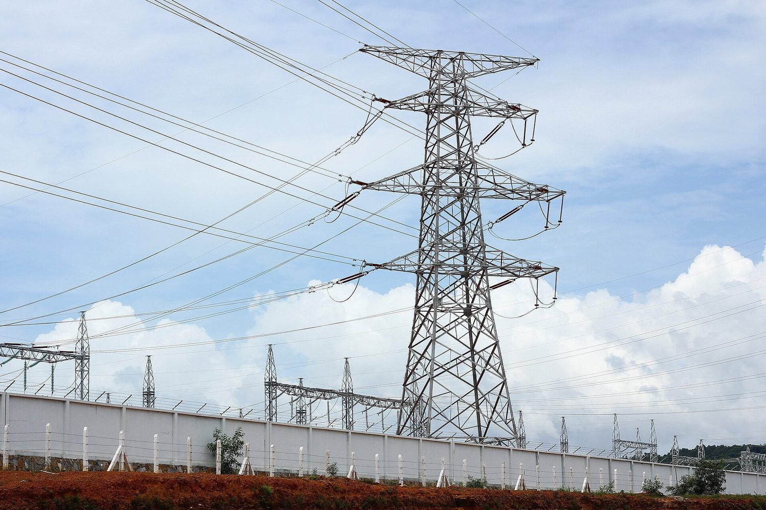
高圧送電線:電流(および I²R 損失)を抑えるため、電気出力は高電圧で送電される
Explore · ⁨探索⁩

Read an I-V characteristic · ⁨I-V特性曲線を読む⁩

Power is $P=IV$. A resistor's I-V line is straight, but a lamp curves as it heats and its resistance rises. The area under I-V relates to the energy delivered. · ⁨電力は $P=IV$ 。抵抗器の I-V 線は直線だが、ランプ は発熱して抵抗が増すため曲線になる。I-V 下面積は供給されたエネルギーに関係する。⁩

11.5

Compound DC Circuits · ⁨複合DC回路⁩

Syllabus · ⁨シラバス⁩
English

Learning Objective 11.5.A: Describe the equivalent resistance of multiple resistors connected in a circuit.

  • 11.5.A.1 Circuit elements may be connected in series and/or in parallel.
    • 11.5.A.1.i A series connection is one in which any charge passing through one circuit element must proceed through all elements in that connection and has no other path available. The current in each element in series must be the same.
    • 11.5.A.1.ii A parallel connection is one in which charges may flow through one of two or more paths. Across each path, the potential difference is the same.
  • 11.5.A.2 A collection of resistors in a circuit may be analyzed as though it were a single resistor with an equivalent resistance $R_{\text{eq}}$.
    • 11.5.A.2.i The equivalent resistance of a set of resistors in series is the sum of the individual resistances.
      • Equation: $R_{\text{eq},s} = \sum_i R_i$
    • 11.5.A.2.ii The inverse of the equivalent resistance of a set of resistors connected in parallel is equal to the sum of the inverses of the individual resistances.
      • Equation: $\dfrac{1}{R_{\text{eq},p}} = \sum_i \dfrac{1}{R_i}$
    • 11.5.A.2.iii When resistors are connected in parallel, the number of paths available to charges increases, and the equivalent resistance of the group of resistors decreases.

Learning Objective 11.5.B: Describe a circuit with resistive wires and a battery with internal resistance.

  • 11.5.B.1 Ideal batteries have negligible internal resistance. Ideal wires have negligible resistance.
    • 11.5.B.1.i The resistance of wires that are good conductors may normally be neglected, because their resistance is much smaller than that of other elements of a circuit.
    • 11.5.B.1.ii The resistance of wires may only be neglected if the circuit contains other elements that do have resistance.
    • 11.5.B.1.iii The potential difference a battery would supply if it were ideal is the potential difference measured across the terminals when there is no current in the battery and is sometimes referred to as its $\mathrm{emf}$ ($\varepsilon$).
  • 11.5.B.2 The internal resistance of a nonideal battery may be treated as the resistance of a resistor in series with an ideal battery and the remainder of the circuit.
  • 11.5.B.3 When there is current in a nonideal battery with internal resistance $r$, the potential difference across the terminals of the battery is reduced relative to the potential difference when there is no current in the battery.
    • Equation (derived): $\Delta V_{\text{terminal}} = \varepsilon - Ir$

Learning Objective 11.5.C: Describe the measurement of current and potential difference in a circuit.

  • 11.5.C.1 Ammeters are used to measure current at a specific point in a circuit.
    • 11.5.C.1.i Ammeters must be connected in series with the element in which current is being measured.
    • 11.5.C.1.ii Ideal ammeters have zero resistance so that they do not affect the current in the element that they are in series with.
  • 11.5.C.2 Voltmeters are used to measure electric potential difference between two points in a circuit.
    • 11.5.C.2.i Voltmeters must be connected in parallel with the element across which potential difference is being measured.
    • 11.5.C.2.ii Ideal voltmeters have an infinite resistance so that no charge flows through them.
  • 11.5.C.3 Nonideal ammeters and voltmeters will change the properties of the circuit being measured.

Boundary statement: AP Physics 2 only expects students to qualitatively discuss how a nonideal ammeter or voltmeter will affect the results of measurements. Unless otherwise stated, all batteries, wires, and meters are assumed to be ideal.

Boundary statement: Circuits with batteries of different potential differences connected in parallel will not be assessed.

日本語

学習目標 11.5.A: 回路に接続された複数の抵抗器の等価抵抗を説明せよ。

  • 11.5.A.1 回路素子は直列および/または並列に接続されることができる。
    • 11.5.A.1.i 直列接続とは、ある回路素子を通過した電荷がその接続にあるすべての素子を通過せねばならず、他の経路が存在しない状態である。直列接続された各素子の電流は同じでなければならない。
    • 11.5.A.1.ii 並列接続とは、電荷が2つ以上の経路のうちいずれか一つを通って流れる接続方法である。各経路間での電位差は等しい。
  • 11.5.A.2 回路中の抵抗器の組み合わせは、等価抵抗 $R_{\text{eq}}$ を持つ単一の抵抗器として解析できる。
    • 11.5.A.2.i 直列に接続された抵抗器の等価抵抗は、個々の抵抗値の総和である。
      • 数式: $R_{\text{eq},s} = \sum_i R_i$
    • 11.5.A.2.ii 並列に接続された抵抗器の等価抵抗の逆数は、個々の抵抗値の逆数の総和に等しい。
      • 数式: $\dfrac{1}{R_{\text{eq},p}} = \sum_i \dfrac{1}{R_i}$
    • 11.5.A.2.iii 抵抗器を並列に接続すると、電荷が流れることができる経路の数が増加し、抵抗器群の等価抵抗は減少する。

学習目標 11.5.B: 抵抗性導線と内部抵抗を持つ電池を含む回路を説明せよ。

  • 11.5.B.1 理想電池は内部抵抗を無視できるほど小さいとする。理想導線もまた抵抗を無視できるほど小さいとする。
    • 11.5.B.1.i 良好な伝導体である導線の抵抗は通常無視できる。これは、その抵抗が回路他の要素の抵抗よりもはるかに小さいためである。
    • 11.5.B.1.ii 回路中に抵抗を持つ他の要素が存在する場合のみ、導線の抵抗は無視できる。
    • 11.5.B.1.iii 理想電池であれば供給されるはずの電位差は、電池に電流が流れていないときに端子間で測定される電位差であり、この値は $\mathrm{emf}$($\varepsilon$)とも呼ばれる。
  • 11.5.B.2 非理想電池の内部抵抗は、理想電池と回路残部との間に直列に接続された抵抗器の抵抗として扱うことができる。
  • 11.5.B.3 内部抵抗 $r$ を持つ非理想電池に電流が流れている場合、端子間の電位差は、電池に電流が流れていないときの電位差より小さくなる。
    • 式(導出): $\Delta V_{\text{terminal}} = \varepsilon - Ir$

学習目標 11.5.C: 回路における電流および電位差の測定方法を説明せよ。

  • 11.5.C.1 アメーターは、回路内の特定の点における電流を測定するために用いられる。
    • 11.5.C.1.i アメーターは、電流を測定したい素子と直列に接続しなければならない。
    • 11.5.C.1.ii 理想アメーターは抵抗がゼロであるため、直列に接続した素子の電流に影響を与えない。
  • 11.5.C.2 ボルトメーターは、回路内の2点間の電気的電位差を測定するために用いられる。
    • 11.5.C.2.i ボルトメーターは、電位差を測定したい素子と並列に接続しなければならない。
    • 11.5.C.2.ii 理想ボルトメーターは抵抗が無限大であるため、電荷が流れない。
  • 11.5.C.3 非理想のアメーターやボルトメーターを用いると、測定対象の回路の性質が変化する。

境界文: AP Physics 2では、学生に対して非理想のアメーターまたはボルトメーターが測定結果に与える影響について定性的に議論することを求めるのみである。特に指示がない限り、すべての電池、導線、計測器は理想のものであると仮定される。

境界文: 異なる電位差を持つ電池が並列に接続された回路については評価しない。

Source: College Board AP Course and Exam Description · ⁨出典: College Board AP コースおよび試験説明書⁩

English

Combine resistors to find an equivalent resistance 等效电阻:

  • Series: $R_{\text{eq}}=R_1+R_2+\cdots$ (resistances add).
  • Parallel: $\dfrac{1}{R_{\text{eq}}}=\dfrac{1}{R_1}+\dfrac{1}{R_2}+\cdots$ (the total is less than the smallest).

Reduce the network step by step to find the total current from the battery, then work back to each element.

Worked example. A $12\ \text{V}$ battery drives a $4.0\ \Omega$ and a $12\ \Omega$ resistor in parallel. First combine them: $\dfrac{1}{R_{\text{eq}}}=\dfrac14+\dfrac{1}{12}=\dfrac{4}{12}\Rightarrow R_{\text{eq}}=3.0\ \Omega$. The total current from the battery is $I=\dfrac{V}{R_{\text{eq}}}=\dfrac{12}{3.0}=4.0\ \text{A}$, which splits so that the smaller resistor carries the larger share ($3.0\ \text{A}$ through the $4\ \Omega$, $1.0\ \text{A}$ through the $12\ \Omega$).

日本語

抵抗器を結合して等価抵抗を見出します:

直列接続の抵抗は合成抵抗に合計される
直列接続の抵抗は合成抵抗に合計される
  • 直列: $R_{\text{eq}}=R_1+R_2+\cdots$ (抵抗値が加算される)。
  • 並列: $\dfrac{1}{R_{\text{eq}}}=\dfrac{1}{R_1}+\dfrac{1}{R_2}+\cdots$ (全体は最小値より小さい)。

回路を段階的に単純化して、電源からの全電流を求め、そこから各素子に戻って計算する。

** worked example(例題)。** $12\ \text{V}$ の電源から $4.0\ \Omega$ と $12\ \Omega$ の抵抗が並列に接続されている。まずこれらを合成する: $\dfrac{1}{R_{\text{eq}}}=\dfrac14+\dfrac{1}{12}=\dfrac{4}{12}\Rightarrow R_{\text{eq}}=3.0\ \Omega$。電源からの全電流は $I=\dfrac{V}{R_{\text{eq}}}=\dfrac{12}{3.0}=4.0\ \text{A}$ であり、これが分流して、抵抗が小さい方により大きな電流が流れる($3.0\ \text{A}$ が $4\ \Omega$ を通り、$1.0\ \text{A}$ が $12\ \Omega$ を通る)。

11.5

Measuring Current and Voltage · ⁨電流と電圧の測定⁩

Syllabus · ⁨シラバス⁩
English

Learning Objective 11.5.A: Describe the equivalent resistance of multiple resistors connected in a circuit.

  • 11.5.A.1 Circuit elements may be connected in series and/or in parallel.
    • 11.5.A.1.i A series connection is one in which any charge passing through one circuit element must proceed through all elements in that connection and has no other path available. The current in each element in series must be the same.
    • 11.5.A.1.ii A parallel connection is one in which charges may flow through one of two or more paths. Across each path, the potential difference is the same.
  • 11.5.A.2 A collection of resistors in a circuit may be analyzed as though it were a single resistor with an equivalent resistance $R_{\text{eq}}$.
    • 11.5.A.2.i The equivalent resistance of a set of resistors in series is the sum of the individual resistances.
      • Equation: $R_{\text{eq},s} = \sum_i R_i$
    • 11.5.A.2.ii The inverse of the equivalent resistance of a set of resistors connected in parallel is equal to the sum of the inverses of the individual resistances.
      • Equation: $\dfrac{1}{R_{\text{eq},p}} = \sum_i \dfrac{1}{R_i}$
    • 11.5.A.2.iii When resistors are connected in parallel, the number of paths available to charges increases, and the equivalent resistance of the group of resistors decreases.

Learning Objective 11.5.B: Describe a circuit with resistive wires and a battery with internal resistance.

  • 11.5.B.1 Ideal batteries have negligible internal resistance. Ideal wires have negligible resistance.
    • 11.5.B.1.i The resistance of wires that are good conductors may normally be neglected, because their resistance is much smaller than that of other elements of a circuit.
    • 11.5.B.1.ii The resistance of wires may only be neglected if the circuit contains other elements that do have resistance.
    • 11.5.B.1.iii The potential difference a battery would supply if it were ideal is the potential difference measured across the terminals when there is no current in the battery and is sometimes referred to as its $\mathrm{emf}$ ($\varepsilon$).
  • 11.5.B.2 The internal resistance of a nonideal battery may be treated as the resistance of a resistor in series with an ideal battery and the remainder of the circuit.
  • 11.5.B.3 When there is current in a nonideal battery with internal resistance $r$, the potential difference across the terminals of the battery is reduced relative to the potential difference when there is no current in the battery.
    • Equation (derived): $\Delta V_{\text{terminal}} = \varepsilon - Ir$

Learning Objective 11.5.C: Describe the measurement of current and potential difference in a circuit.

  • 11.5.C.1 Ammeters are used to measure current at a specific point in a circuit.
    • 11.5.C.1.i Ammeters must be connected in series with the element in which current is being measured.
    • 11.5.C.1.ii Ideal ammeters have zero resistance so that they do not affect the current in the element that they are in series with.
  • 11.5.C.2 Voltmeters are used to measure electric potential difference between two points in a circuit.
    • 11.5.C.2.i Voltmeters must be connected in parallel with the element across which potential difference is being measured.
    • 11.5.C.2.ii Ideal voltmeters have an infinite resistance so that no charge flows through them.
  • 11.5.C.3 Nonideal ammeters and voltmeters will change the properties of the circuit being measured.

Boundary statement: AP Physics 2 only expects students to qualitatively discuss how a nonideal ammeter or voltmeter will affect the results of measurements. Unless otherwise stated, all batteries, wires, and meters are assumed to be ideal.

Boundary statement: Circuits with batteries of different potential differences connected in parallel will not be assessed.

日本語

学習目標 11.5.A: 回路に接続された複数の抵抗器の等価抵抗を説明せよ。

  • 11.5.A.1 回路素子は直列および/または並列に接続されることができる。
    • 11.5.A.1.i 直列接続とは、ある回路素子を通過した電荷がその接続にあるすべての素子を通過せねばならず、他の経路が存在しない状態である。直列接続された各素子の電流は同じでなければならない。
    • 11.5.A.1.ii 並列接続とは、電荷が2つ以上の経路のうちいずれか一つを通って流れる接続方法である。各経路間での電位差は等しい。
  • 11.5.A.2 回路中の抵抗器の組み合わせは、等価抵抗 $R_{\text{eq}}$ を持つ単一の抵抗器として解析できる。
    • 11.5.A.2.i 直列に接続された抵抗器の等価抵抗は、個々の抵抗値の総和である。
      • 数式: $R_{\text{eq},s} = \sum_i R_i$
    • 11.5.A.2.ii 並列に接続された抵抗器の等価抵抗の逆数は、個々の抵抗値の逆数の総和に等しい。
      • 数式: $\dfrac{1}{R_{\text{eq},p}} = \sum_i \dfrac{1}{R_i}$
    • 11.5.A.2.iii 抵抗器を並列に接続すると、電荷が流れることができる経路の数が増加し、抵抗器群の等価抵抗は減少する。

学習目標 11.5.B: 抵抗性導線と内部抵抗を持つ電池を含む回路を説明せよ。

  • 11.5.B.1 理想電池は内部抵抗を無視できるほど小さいとする。理想導線もまた抵抗を無視できるほど小さいとする。
    • 11.5.B.1.i 良好な伝導体である導線の抵抗は通常無視できる。これは、その抵抗が回路他の要素の抵抗よりもはるかに小さいためである。
    • 11.5.B.1.ii 回路中に抵抗を持つ他の要素が存在する場合のみ、導線の抵抗は無視できる。
    • 11.5.B.1.iii 理想電池であれば供給されるはずの電位差は、電池に電流が流れていないときに端子間で測定される電位差であり、この値は $\mathrm{emf}$($\varepsilon$)とも呼ばれる。
  • 11.5.B.2 非理想電池の内部抵抗は、理想電池と回路残部との間に直列に接続された抵抗器の抵抗として扱うことができる。
  • 11.5.B.3 内部抵抗 $r$ を持つ非理想電池に電流が流れている場合、端子間の電位差は、電池に電流が流れていないときの電位差より小さくなる。
    • 式(導出): $\Delta V_{\text{terminal}} = \varepsilon - Ir$

学習目標 11.5.C: 回路における電流および電位差の測定方法を説明せよ。

  • 11.5.C.1 アメーターは、回路内の特定の点における電流を測定するために用いられる。
    • 11.5.C.1.i アメーターは、電流を測定したい素子と直列に接続しなければならない。
    • 11.5.C.1.ii 理想アメーターは抵抗がゼロであるため、直列に接続した素子の電流に影響を与えない。
  • 11.5.C.2 ボルトメーターは、回路内の2点間の電気的電位差を測定するために用いられる。
    • 11.5.C.2.i ボルトメーターは、電位差を測定したい素子と並列に接続しなければならない。
    • 11.5.C.2.ii 理想ボルトメーターは抵抗が無限大であるため、電荷が流れない。
  • 11.5.C.3 非理想のアメーターやボルトメーターを用いると、測定対象の回路の性質が変化する。

境界文: AP Physics 2では、学生に対して非理想のアメーターまたはボルトメーターが測定結果に与える影響について定性的に議論することを求めるのみである。特に指示がない限り、すべての電池、導線、計測器は理想のものであると仮定される。

境界文: 異なる電位差を持つ電池が並列に接続された回路については評価しない。

Source: College Board AP Course and Exam Description · ⁨出典: College Board AP コースおよび試験説明書⁩

English

Two meters read a circuit. An ammeter 电流表 measures the current at a point, so it must be wired in series – the current you want to measure has to flow through it. A voltmeter 电压表 measures the potential difference between two points, so it is wired in parallel, bridging across the component whose voltage you want.

For a meter to read the true value it must barely disturb the circuit:

  • an ideal ammeter has zero resistance, so putting it in series does not reduce the current it reads;
  • an ideal voltmeter has infinite resistance, so almost no current is diverted through it.

A real, nonideal 非理想 meter is imperfect: a real ammeter has a small resistance (it slightly lowers the current), and a real voltmeter lets a little current leak through (it slightly lowers the voltage it reads). So connecting any meter changes, a little, the very quantity it is measuring.

日本語

2つのメーターが回路を読み取る。アンメーターは特定の点における電流を測定するため、直列に接続する必要がある– 測定したい電流が必ず通過しなければならない。ボルトメーターは2点間の電位差を測定するため、並列に接続し、測定したい電圧のある部品の両端に跨ぐようにつなぐ。

メーターが真の値を表示するには、回路への影響が極めて小さくなければならない:

  • 理想的アンメーターは抵抗ゼロであるため、直列に接続しても表示される電流を減少させない;
  • 理想的ボルトメーターは無限大の抵抗を持つため、ほぼ電流が流れない。

実際の非理想型メーターは不完全である:実在するアンメーターには小さな抵抗があり(電流をわずかに下げる)、実在するボルトメーターはわずかな電流を漏らす(表示される電圧をわずかに下げる)。したがって、いかなるメーターを接続しても、測定しようとしている量そのものがわずかに変化する。

11.6

Kirchhoff's Loop Rule · ⁨キルヒホッフのループ則⁩

Syllabus · ⁨シラバス⁩
English

Learning Objective 11.6.A: Describe a circuit or elements of a circuit by applying Kirchhoff's loop rule.

  • 11.6.A.1 Energy changes in simple electrical circuits may be represented in terms of charges moving through electric potential differences within circuit elements.
    • Equation: $\Delta U_E = q \Delta V$
  • 11.6.A.2 Kirchhoff's loop rule is a consequence of the conservation of energy.
  • 11.6.A.3 Kirchhoff's loop rule states that the sum of potential differences across all circuit elements in a single closed loop must equal zero.
    • Equation: $\sum \Delta V = 0$
  • 11.6.A.4 The values of electric potential at points in a circuit can be represented by a graph of electric potential as a function of position within a loop.
日本語

学習目標 11.6.A: キルヒホッフのループ則を用いて、回路または回路の要素を説明せよ。

  • 11.6.A.1 単純な電気回路におけるエネルギーの変化は、電荷が回路要素内の電位差を通過して移動することによって表すことができる。
    • 式: $\Delta U_E = q \Delta V$
  • 11.6.A.2 キルヒホッフのループ則はエネルギー保存則の結果である。
  • 11.6.A.3 キルヒホッフのループ則は、単一の閉回路内のすべての回路素子間の電位差の総和がゼロに等しいことを示す。
    • 式: $\sum \Delta V = 0$
  • 11.6.A.4 回路内の点における電位の値は、ループ内での位置に対する電位のプロットで表現できる。

Source: College Board AP Course and Exam Description · ⁨出典: College Board AP コースおよび試験説明書⁩

English

Kirchhoff's loop rule 基尔霍夫电压定律 (energy conservation): around any closed loop, the voltage gains and drops sum to zero. Add the battery's emf and subtract each $IR$ drop as you go around. This gives one equation per independent loop.

日本語

キルヒホッフのループ則(エネルギー保存):任意の閉じたループにおいて、電圧の上昇と低下の総和はゼロとなる。ループ内を一周する際に、電源の起電力を加え、各 $IR$ の降下を引く。これにより、独立したループごとに1式が得られる。

11.7

Kirchhoff's Junction Rule · ⁨キルヒホッフの接点則⁩

Syllabus · ⁨シラバス⁩
English

Learning Objective 11.7.A: Describe a circuit or elements of a circuit by applying Kirchhoff's junction rule.

  • 11.7.A.1 Kirchhoff's junction rule is a consequence of the conservation of electric charge.
  • 11.7.A.2 Kirchhoff's junction rule states that the total amount of charge entering a junction per unit time must equal the total amount of charge exiting that junction per unit time.
    • Equation: $\sum I_{\text{in}} = \sum I_{\text{out}}$
日本語

学習目標 11.7.A: キルヒホッフの節則を用いて、回路または回路の要素を説明せよ。

  • 11.7.A.1 キルヒホッフの節則は電気電荷保存則の結果である。
  • 11.7.A.2 キルヒホッフの節則とは、単位時間あたりに節点に流入する電荷の総量は、単位時間あたりにその節点から流出する電荷の総量に等しいという法則である。
    • 式: $\sum I_{\text{in}} = \sum I_{\text{out}}$

Source: College Board AP Course and Exam Description · ⁨出典: College Board AP コースおよび試験説明書⁩

English

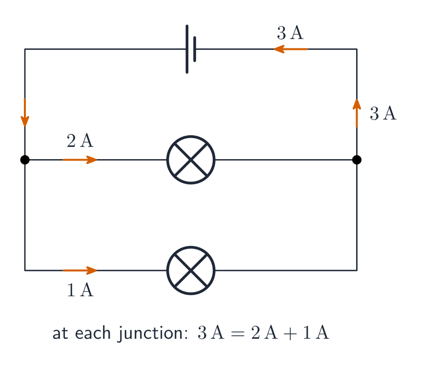
Kirchhoff's junction rule 基尔霍夫电流定律 (charge conservation): the total current into any junction equals the total current out. Together with the loop rule, it lets you solve any multi-loop circuit for its unknown currents.

日本語

キルヒホッフの接点則(電荷保存):任意の接点へ流入する全電流は、流出する全電流に等しい。ループ則と併用することで、複数のループを持つ回路の未知電流を解くことができる。

接点で電流が分流する:流入量と流出量は等しい
11.8

RC Circuits · ⁨RC回路⁩

Syllabus · ⁨シラバス⁩
English

Learning Objective 11.8.A: Describe the equivalent capacitance of multiple capacitors.

  • 11.8.A.1 A collection of capacitors in a circuit may be analyzed as though it were a single capacitor with an equivalent capacitance $C_{\text{eq}}$.
    • 11.8.A.1.i The inverse of the equivalent capacitance of a set of capacitors connected in series is equal to the sum of the inverses of the individual capacitances.
      • Equation: $\dfrac{1}{C_{\text{eq},s}} = \sum_i \dfrac{1}{C_i}$
    • 11.8.A.1.ii The equivalent capacitance of a set of capacitors in series is less than the capacitance of the smallest capacitor.
    • 11.8.A.1.iii The equivalent capacitance of a set of capacitors in parallel is the sum of the individual capacitances.
      • Equation: $C_{\text{eq},p} = \sum_i C_i$
  • 11.8.A.2 As a result of conservation of charge, each of the capacitors in series must have the same magnitude of charge on each plate.

Learning Objective 11.8.B: Describe the behavior of a circuit containing combinations of resistors and capacitors.

  • 11.8.B.1 The time constant $\tau$ is a significant feature of an RC circuit.
    • 11.8.B.1.i The time constant of an RC circuit is a measure of how quickly the capacitor will charge or discharge and is defined as $\tau = R_{\text{eq}} C_{\text{eq}}$.
    • 11.8.B.1.ii For a charging capacitor, the time constant represents the time required for the capacitor's charge to increase from zero to approximately 63 percent of its final asymptotic value.
    • 11.8.B.1.iii For a discharging capacitor, the time constant represents the time required for the capacitor's charge to decrease from fully charged to approximately 37 percent of its initial value.
  • 11.8.B.2 The potential difference across a capacitor and the current in the branch of the circuit containing the capacitor each change over time as the capacitor charges and discharges, but both will reach a steady state after a long time interval.
    • 11.8.B.2.i Immediately after being placed in a circuit, an uncharged capacitor acts like a wire, and charge can easily flow to or from the plates of the capacitor.
    • 11.8.B.2.ii As a capacitor charges, changes to the potential difference across the capacitor affect the charge on the plates of the capacitor, the current circuit branch in which the capacitor is located, and the electric potential energy stored in the capacitor.
    • 11.8.B.2.iii The potential difference across a capacitor, the current in the circuit branch in which the capacitor is located, and the electric potential energy stored in the capacitor all change with respect to time and asymptotically approach steady state conditions.
    • 11.8.B.2.iv After a long time, a charging capacitor approaches a state of being fully charged, reaching a maximum potential difference at which there is zero current in the circuit branch in which the capacitor is located.
    • 11.8.B.2.v Immediately after a charged capacitor begins discharging, the amount of charge on the capacitor plates and the energy stored in the capacitor begin to decrease.
    • 11.8.B.2.vi As a capacitor discharges, the amount of charge on the capacitor, the potential difference across the capacitor, and the current in the circuit branch in which the capacitor is located all decrease until a steady state is reached.
    • 11.8.B.2.vii After either charging or discharging for times much greater than the time constant, the capacitor and the relevant circuit branch may be modeled using steady-state conditions.

Boundary statement: Descriptions of charging/discharging RC circuits in AP Physics 2 are limited to qualitative descriptions and representations. While students should be able to mathematically describe initial and final states of RC circuits, students are not expected to mathematically model these behaviors with respect to time.

日本語

学習目標 11.8.A: 複数のコンデンサの等価静電容量を説明せよ。

  • 11.8.A.1 回路中のコンデンサの組み合わせは、等価静電容量 $C_{\text{eq}}$ を持つ単一のコンデンサとして解析できる。
    • 11.8.A.1.i 直列に接続されたコンデンサの等価静電容量の逆数は、個々の静電容量の逆数の総和に等しい。
      • 数式: $\dfrac{1}{C_{\text{eq},s}} = \sum_i \dfrac{1}{C_i}$
    • 11.8.A.1.ii 直列に接続されたコンデンサの等価静電容量は、最も小さなコンデンサの静電容量より小さい。
    • 11.8.A.1.iii 並列に接続されたコンデンサの等価静電容量は、個々の静電容量の総和である。
      • 数式: $C_{\text{eq},p} = \sum_i C_i$
  • 11.8.A.2 電荷保存則の結果、直列に接続された各コンデンサの各極板には同じ大きさの電荷が蓄えられる。

学習目標 11.8.B: 抵抗器とコンデンサの組み合わせを含む回路の挙動を説明せよ。

  • 11.8.B.1 時間定数 $\tau$ はRC回路の重要な特徴である。
    • 11.8.B.1.i RC回路の時間定数は、コンデンサの充電または放電の速さを示す指標であり、定義式は $\tau = R_{\text{eq}} C_{\text{eq}}$ である。
    • 11.8.B.1.ii 充電中のコンデンサにおいて、時間定数は、コンデンサの電荷がゼロから最終的な漸近値の約63%に増加するまでに要する時間を表す。
    • 11.8.B.1.iii 放電中のコンデンサにおいて、時間定数は、コンデンサの電荷が完全に充電された状態から初期値の約37%に減少するまでに要する時間を表す。
  • 11.8.B.2 コンデンサ両端の電位差と、コンデンサを含む回路の分路における電流は、コンデンサの充放電に伴って時間とともに変化するが、長期間経過すれば両方とも定常状態に達する。
    • 11.8.B.2.i 回路に接続された直後、未充電のコンデンサは導線のように振る舞い、電荷がコンデンサの極板へ容易に流入または流出する。
    • 11.8.B.2.ii コンデンサが充電されるにつれて、コンデンサ両端の電位差の変化は、コンデンサの極板上の電荷量、コンデンサを含む回路分路の電流、およびコンデンサに蓄えられた静電エネルギーに影響を与える。
    • 11.8.B.2.iii コンデンサ両端の電位差、コンデンサを含む回路分路の電流、およびコンデンサに蓄えられた静電エネルギーはすべて時間とともに変化し、漸近的に定常状態に近づく。
    • 11.8.B.2.iv 長期間経過すると、充電中のコンデンサは完全に充電された状態に近づき、コンデンサを含む回路分路における電流がゼロとなる最大電位差に達する。
    • 11.8.B.2.v 充電されたコンデンサの放電が始まった直後、コンデンサの極板上の電荷量およびコンデンサに蓄えられたエネルギーは減少を始める。
    • 11.8.B.2.vi コンデンサが放電されるにつれて、コンデンサの電荷量、コンデンサ両端の電位差、およびコンデンサを含む回路分路の電流はすべて減少し、定常状態に達するまで続く。
    • 11.8.B.2.vii 充放電の時間が時間定数に比べて非常に長い場合、コンデンサおよび関連する回路分路は定常状態の条件を用いてモデル化できる。

境界文: AP Physics 2におけるRC回路の充放電に関する記述は、定性的な記述と表現に限定される。学生はRC回路の初期状態および最終状態を数学的に記述できるべきであるが、これらの挙動を時間に対する数学的モデルとして扱うことは求められない。

Source: College Board AP Course and Exam Description · ⁨出典: College Board AP コースおよび試験説明書⁩

English
Charging a capacitor (RC)

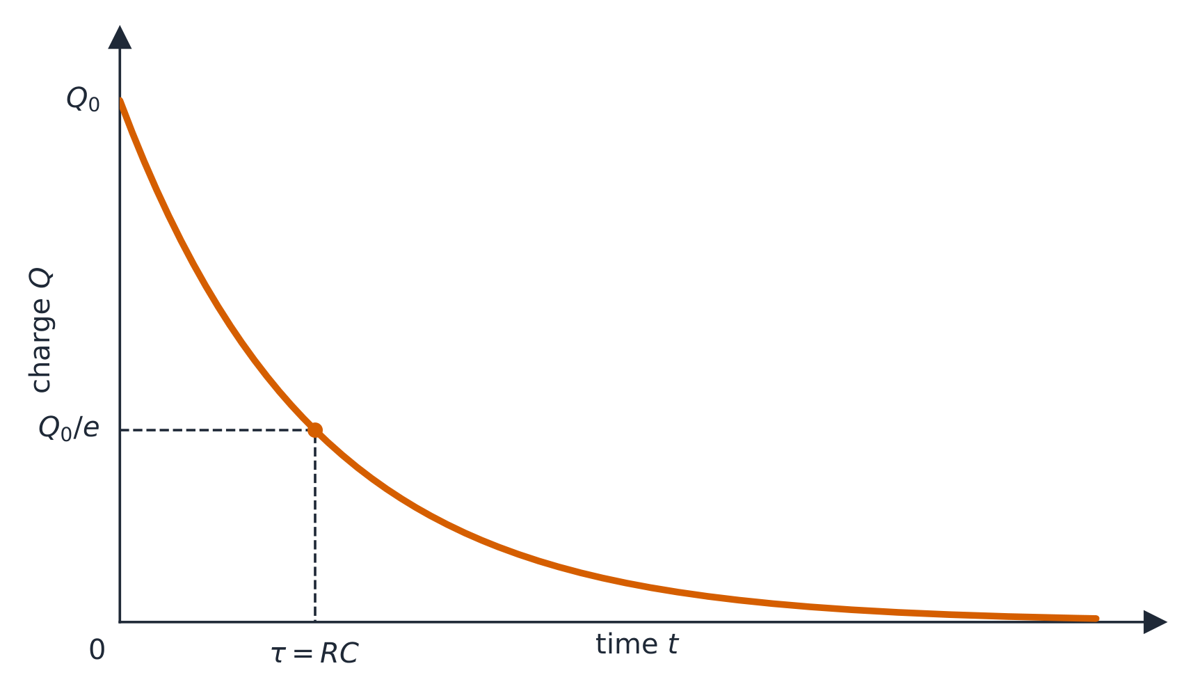
An RC circuit RC电路 contains a resistor and a capacitor. When charging, the capacitor's voltage rises and the current falls, both exponentially, over a characteristic time $\tau=RC$. Key limits: at the first instant the uncharged capacitor acts like a plain wire (maximum current); after a long time it is fully charged and blocks current (acts like a break).

Worked example. For $R=10\ \text{k}\Omega$ and $C=100\ \mu\text{F}$, the time constant is $\tau=RC=(10\times10^{3})(100\times10^{-6})=1.0\ \text{s}$. After one time constant the capacitor reaches about $63\%$ of the supply voltage; after about $5\tau$ it is essentially fully charged.

日本語
コンデンサの充電 (RC)

RC回路 RC は抵抗器とコンデンサを含む。充電時、コンデンサの電圧は上昇し、電流は減少するが、どちらも特徴的な時間 $\tau=RC$ に伴って指数関数的に変化する。重要な極限値として:最初の瞬間、未充電のコンデンサは単なる導線のように振る舞い(最大電流)、長時間経過後は完全に充電され電流を遮断する(開路のように振る舞う)。

コンデンサの放電に伴う電荷の指数関数的減衰

** worked example(例題)。** $R=10\ \text{k}\Omega$ と $C=100\ \mu\text{F}$ に対して、時間定数は $\tau=RC=(10\times10^{3})(100\times10^{-6})=1.0\ \text{s}$ である。1つの時間定数経過後、コンデンサは供給電圧の約 $63\%$ に達し、おおよそ $5\tau$ 経過後にはほぼ完全に充電される。

11.8

Exam tips · ⁨試験対策⁩

English
  • In series the current is the same throughout; in parallel the voltage is the same across each branch — never mix these up.
  • Combine resistors: series add; parallel $1/R_{\text{eq}}=\sum 1/R_i$ (the total is less than the smallest).
  • Apply Kirchhoff's rules: junction (current in = current out, charge conserved) and loop (voltages sum to zero, energy conserved).
  • Pick the power form that fits your knowns: $P=IV=I^2R=V^2/R$.
  • An ammeter goes in series (ideal: zero resistance); a voltmeter goes in parallel (ideal: infinite resistance). A real meter slightly disturbs the circuit it measures.
  • A bulb is brighter when it dissipates more power – in series the biggest resistance ($I^2R$) glows brightest; in parallel the smallest ($V^2/R$) does.
  • In an RC circuit the capacitor acts like a plain wire the instant it starts charging and like a break once fully charged.
日本語
  • 直列では全線で電流が同じであり、並列では各分岐間での電圧が同じ – これらを混同してはいけない。
  • 抵抗を合成する:直列では加算、並列では $1/R_{\text{eq}}=\sum 1/R_i$ (全体は最小値より小さい)。
  • キルヒホッフの法則を適用する:接点則(流入電流=流出電流、電荷保存)とループ則(電圧の総和はゼロ、エネルギー保存)。
  • 既知量に適した電力の形式を選ぶ:$P=IV=I^2R=V^2/R$。
  • アンメーターは直列に接続する(理想的:抵抗ゼロ)、ボルトメーターは並列に接続する(理想的:無限大の抵抗)。実際のメーターは測定対象の回路をわずかに乱す。
  • 電球は消費する電力が多いほど明るくなる – 直列では最大の抵抗($I^2R$)が最も明るく発光し、並列では最小($V^2/R$)が最も明るくなる。
  • RC回路において、コンデンサは充電開始と同時に単なる導線のように振る舞い、完全に充電された後は開路のように振る舞う。

Interactive lessons on this topic · ⁨このトピックのインタラクティブ授業⁩

Work through it step by step, with instant-check exercises. · ⁨一歩ずつ進め、即時チェック付きの問題で学習します。⁩

Past Papers · ⁨過去問⁩

More topics in AP Physics 2 · ⁨AP物理学 2⁩ · ⁨AP Physics 2 · ⁨AP物理学 2⁩ の他のトピック⁩

Log in or create account · ⁨ログインまたはアカウント作成⁩

IGCSE, A-Level & AP