Skip to content · ⁨Lompat ke konten⁩

Electric Circuits · ⁨Rangkaian Listrik⁩

AP Physics 2 · ⁨AP Fisika 2⁩ · Topic 11 · ⁨Topik 11⁩

Video lesson for this topic · ⁨Pelajaran video untuk topik ini⁩ Open the video page · ⁨Buka halaman video⁩
7:45

Rangkaian Listrik

Anda menyalakan sakelar, dan lampu menyala sekaligus. Jadi elektron harus berlari kencang di sepanjang kawat. Mereka tidak. Di dalam tembaga, elektron merayap — kurang dari satu…

English narration · English + 中文 subtitles burned in · ⁨Narasi bahasa Inggris · Subtitle bahasa Inggris + 中文 disematkan langsung⁩

11.1

Electric Current · ⁨Arus Listrik⁩

Syllabus · ⁨Silabus⁩
English

Learning Objective 11.1.A: Describe the movement of electric charges through a medium.

  • 11.1.A.1 Current is the rate at which charge passes through a cross-sectional area of a wire.
    • Equation: $I = \dfrac{\Delta q}{\Delta t}$
    • 11.1.A.1.i Electric charge moves in a circuit in response to an electric potential difference, sometimes referred to as electromotive force, or $\mathrm{emf}$ ($\varepsilon$).
    • 11.1.A.1.ii If the current is zero in a section of wire, the net motion of charge carriers in the wire is also zero, although individual charge carriers will not have zero speed.
  • 11.1.A.2 Although current is not a vector quantity, it does have a direction. The direction of current is associated with what the motion of positive charge would be but not with any coordinate system in space.
    • 11.1.A.2.i The direction of conventional current is chosen to be the direction in which positive charge would move.
    • 11.1.A.2.ii In common circuits, current is actually due to the movement of electrons (negative charge carriers).
Bahasa Indonesia

Tujuan Pembelajaran 11.1.A: Jelaskan pergerakan muatan listrik melalui suatu medium.

  • 11.1.A.1 Arus adalah laju muatan yang melewati luas penampang kawat.
    • Persamaan: $I = \dfrac{\Delta q}{\Delta t}$
    • 11.1.A.1.i Muatan listrik bergerak dalam sirkuit sebagai respons terhadap beda potensial listrik, terkadang disebut sebagai gaya gerak listrik (electromotive force), atau $\mathrm{emf}$ ($\varepsilon$).
    • 11.1.A.1.ii Jika arus bernilai nol pada bagian kawat, maka gerakan bersih pembawa muatan dalam kawat juga nol, meskipun pembawa muatan individu tidak memiliki kecepatan nol.
  • 11.1.A.2 Meskipun arus bukanlah besaran vektor, arus memiliki arah. Arah arus dikaitkan dengan apa yang akan terjadi jika muatan positif bergerak, bukan dengan sistem koordinat mana pun di ruang.
    • 11.1.A.2.i Arah arus konvensional dipilih sebagai arah di mana muatan positif akan bergerak.
    • 11.1.A.2.ii Dalam sirkuit umum, arus sebenarnya disebabkan oleh pergerakan elektron (pembawa muatan negatif).
Source: College Board AP Course and Exam Description · ⁨Sumber: Deskripsi Kursus dan Ujian College Board AP⁩

English

Electric current 电流 is the rate at which charge flows past a point, measured in amperes 安培 (A):

$$I=\frac{\Delta q}{\Delta t}.$$
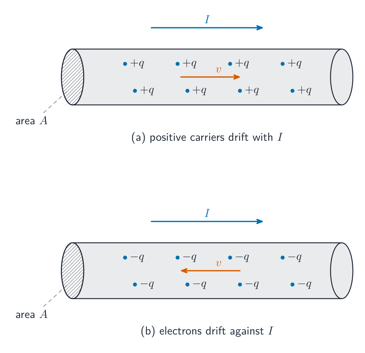
By convention, current points the way positive charge would move (opposite to the electrons in a wire). A steady current needs a complete loop and an energy source (a battery's electromotive force, or emf).

Bahasa Indonesia
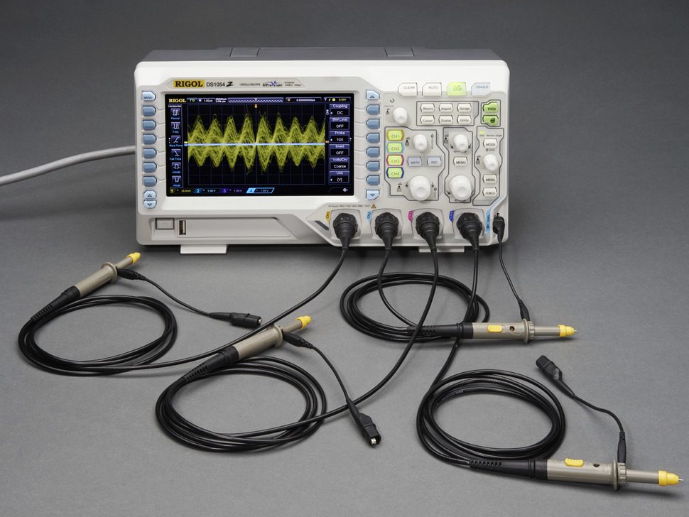
Osiloskop: perilaku rangkaian terhadap waktu diukur sebagai tegangan terhadap waktu
Oscilloskop: perilaku rangkaian terhadap waktu diukur sebagai tegangan terhadap waktu

Arus listrik adalah laju alir muatan melewati suatu titik, diukur dalam ampere (A):

$$I=\frac{\Delta q}{\Delta t}.$$
Secara konvensi, arus mengarah ke tempat muatan positif akan bergerak (berlawanan dengan elektron dalam kawat). Arus stabil memerlukan loop lengkap dan sumber energi (gaya gerak listrik atau emf dari baterai).

Pembawa muatan mengalir lambat melalui konduktor untuk menghasilkan arus
Pembawa muatan melambat merayap melalui konduktor untuk menghasilkan arus
11.2

Simple Circuits · ⁨Rangkaian Sederhana⁩

Syllabus · ⁨Silabus⁩
English

Learning Objective 11.2.A: Describe the behavior of a circuit.

  • 11.2.A.1 A circuit is composed of electrical loops, which may include circuit elements such as wires, batteries, resistors, lightbulbs, capacitors, switches, ammeters, and voltmeters.
  • 11.2.A.2 A closed electrical loop is a closed path through which charges may flow.
    • 11.2.A.2.i A closed circuit is one in which charges would be able to flow.
    • 11.2.A.2.ii An open circuit is one in which charges would not be able to flow.
    • 11.2.A.2.iii A short circuit is one in which charges would be able to flow with no change in potential difference.
  • 11.2.A.3 A single circuit element may be part of multiple electrical loops.
  • 11.2.A.4 Circuit schematics are representations used to describe and analyze electric circuits.
    • 11.2.A.4.i The properties of an electric circuit are dependent on the physical arrangement of its constituent elements.
    • 11.2.A.4.ii Circuit elements have common symbols that are used to create schematic diagrams. Variable elements are indicated by a diagonal strikethrough arrow across the standard symbol for that element. (Standard symbols: Battery, Bulb, Switch, Capacitor, Resistor, Ammeter, Voltmeter.)

Boundary statement: Unless otherwise specified, all circuit schematic diagrams will be drawn using conventional current.

Bahasa Indonesia

Tujuan Pembelajaran 11.2.A: Jelaskan perilaku sebuah sirkuit.

  • 11.2.A.1 Sebuah sirkuit terdiri dari loop listrik, yang dapat mencakup elemen-elemen sirkuit seperti kawat, baterai, resistor, bola lampu, kapasitor, sakelar, ammeter, dan voltmeter.
  • 11.2.A.2 Loop listrik tertutup adalah jalur tertutup tempat muatan dapat mengalir.
    • 11.2.A.2.i Sirkuit tertutup adalah sirkuit di mana muatan dapat mengalir.
    • 11.2.A.2.ii Sirkuit terbuka adalah sirkuit di mana muatan tidak dapat mengalir.
    • 11.2.A.2.iii Sirkuit pendek adalah sirkuit di mana muatan dapat mengalir tanpa perubahan beda potensial.
  • 11.2.A.3 Satu elemen sirkuit mungkin merupakan bagian dari beberapa loop listrik.
  • 11.2.A.4 Skema sirkuit adalah representasi yang digunakan untuk menggambarkan dan menganalisis sirkuit listrik.
    • 11.2.A.4.i Properti dari sebuah sirkuit listrik bergantung pada pengaturan fisik dari elemen-elemen penyusunnya.
    • 11.2.A.4.ii Elemen-elemen sirkuit memiliki simbol-simbol umum yang digunakan untuk membuat diagram skematik. Elemen variabel ditunjukkan dengan panah coret diagonal melintasi simbol standar untuk elemen tersebut. (Simbol standar: Baterai, Bohlam, Sakelar, Kapasitor, Resistor, Ammeter, Voltmeter.)

Pernyataan Batas: Kecuali ditentukan lain, semua diagram skematik sirkuit akan digambar menggunakan arus konvensional.

Source: College Board AP Course and Exam Description · ⁨Sumber: Deskripsi Kursus dan Ujian College Board AP⁩

English

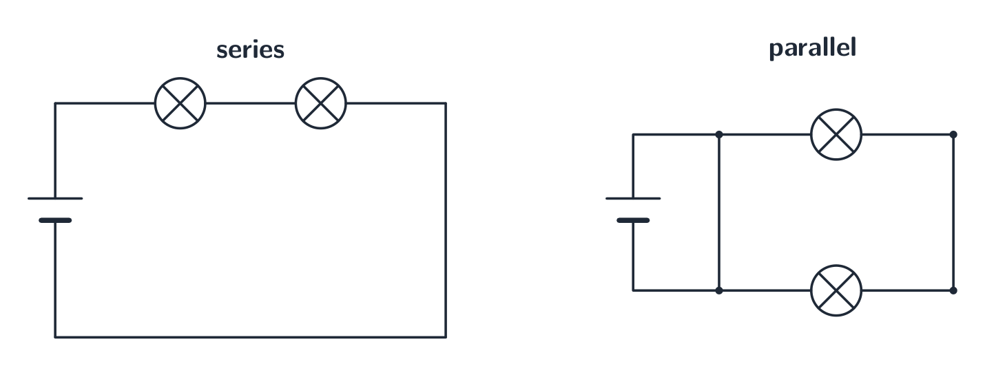
A circuit is a closed loop of conductors, a source (battery), and components. In a series 串联 path the same current flows through each element; in a parallel 并联 path the same voltage is across each branch. A circuit diagram uses standard symbols; reading it correctly is the first step of any circuit problem.

Bahasa Indonesia

Sebuah rangkaian adalah loop tertutup konduktor, sumber (baterai), dan komponen. Dalam jalur seri, arus yang sama mengalir melalui setiap elemen; dalam jalur paralel, tegangan yang sama ada di setiap cabang. Diagram rangkaian menggunakan simbol standar; membacanya dengan benar adalah langkah pertama dari setiap masalah rangkaian.

Komponen dapat dihubungkan secara seri atau paralel
Komponen dapat disambung dalam seri atau paralel
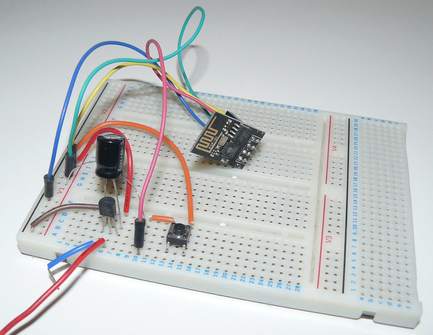
Sirkuit elektronik yang dibangun di atas papan prototipe
Rangkaian nyata: komponen ditekan ke dalam breadboard dan disambung dengan kawat agar arus memiliki lintasan lengkap
Explore · ⁨Jelajahi⁩

Build series and parallel circuits · ⁨Bangun rangkaian seri dan paralel⁩

In series the same current flows through every bulb and voltage divides; in parallel each branch gets the full voltage. Switch mode to see the bulbs' brightness change. · ⁨Dalam seri, arus yang sama mengalir melalui setiap bola lampu dan tegangan terbagi; dalam paralel, setiap cabang mendapat tegangan penuh. Ubah mode untuk melihat perubahan kecerahan bola lampu.⁩

Vocabulary · ⁨Kosa kata⁩ Train · ⁨Latih⁩
English Bahasa Indonesia
Electric current/ɪˈlektrɪk ˈkʌrənt/ Arus listrik
amperes/ˈæmpeəz/ ampere
series/ˈsɪəriːz/ seri
parallel/ˈpærəlel/ paralel
Resistance/rɪˈzɪstəns/ Penolakan
Ohm's law/əʊmz lɔː/ Hukum Ohm
resistivity/ˌriːzɪˈstɪvəti/ resistivitas
Electric power/ɪˈlektrɪk ˈpaʊə/ Daya listrik
light bulb/laɪt bʌlb/ Bohlam lampu
brightness/ˈbraɪtnəs/ kecerahan
equivalent resistance/ɪˈkwɪvələnt rɪˈzɪstəns/ resistansi ekuivalen
11.3

Resistance, Resistivity, and Ohm's Law · ⁨Resistansi, Resistivitas, dan Hukum Ohm⁩

Syllabus · ⁨Silabus⁩
English

Learning Objective 11.3.A: Describe the resistance of an object using physical properties of that object.

  • 11.3.A.1 Resistance is a measure of the degree to which an object opposes the movement of electric charge.
  • 11.3.A.2 The resistance of a resistor with uniform geometry is proportional to its resistivity and length and is inversely proportional to its cross-sectional area.
    • Equation: $R = \dfrac{\rho \ell}{A}$
    • 11.3.A.2.i Resistivity is a fundamental property of a material that depends on its atomic and molecular structure and quantifies how strongly the material opposes the motion of electric charge.
    • 11.3.A.2.ii The resistivity of a conductor typically increases with temperature.

Learning Objective 11.3.B: Describe the electrical characteristics of elements of a circuit.

  • 11.3.B.1 Ohm's law relates current, resistance, and potential difference across a conductive element of a circuit.
    • Equation: $I = \dfrac{\Delta V}{R}$
    • 11.3.B.1.i Materials that obey Ohm's law have constant resistance for all currents and are called ohmic materials.
    • 11.3.B.1.ii The resistivity of an ohmic material is constant regardless of temperature.
    • 11.3.B.1.iii Resistors can also convert electrical energy to thermal energy, which may change the temperature of both the resistor and the resistor's environment.
    • 11.3.B.1.iv The resistance of an ohmic circuit element can be determined from the slope of a graph of the current in the element as a function of the potential difference across the element.
Bahasa Indonesia

Tujuan Pembelajaran 11.3.A: Jelaskan resistansi suatu objek menggunakan sifat fisik dari objek tersebut.

  • 11.3.A.1 Resistansi adalah ukuran seberapa besar suatu objek menolak pergerakan muatan listrik.
  • 11.3.A.2 Resistansi dari sebuah resistor dengan geometri seragam berbanding lurus dengan resistivitas dan panjangnya, serta berbanding terbalik dengan luas penampangnya.
    • Persamaan: $R = \dfrac{\rho \ell}{A}$
    • 11.3.A.2.i Resistivitas adalah sifat fundamental dari suatu material yang bergantung pada struktur atom dan molekulnya, serta mengkuantifikasi seberapa kuat material tersebut menolak pergerakan muatan listrik.
    • 11.3.A.2.ii Resistivitas konduktor biasanya meningkat seiring dengan kenaikan suhu.

Tujuan Pembelajaran 11.3.B: Jelaskan karakteristik listrik dari elemen-elemen sebuah sirkuit.

  • 11.3.B.1 Hukum Ohm menghubungkan arus, resistansi, dan beda potensial pada elemen konduktif dalam sebuah sirkuit.
    • Persamaan: $I = \dfrac{\Delta V}{R}$
    • 11.3.B.1.i Material yang mematuhi Hukum Ohm memiliki resistansi tetap untuk semua arus dan disebut material ohmik.
    • 11.3.B.1.ii Resistivitas material ohmik tetap terlepas dari suhu.
    • 11.3.B.1.iii Resistor juga dapat mengubah energi listrik menjadi energi termal, yang dapat mengubah suhu resistor maupun lingkungan sekitarnya.
    • 11.3.B.1.iv Resistansi elemen sirkuit ohmik dapat ditentukan dari kemiringan grafik arus pada elemen tersebut sebagai fungsi dari beda potensial melintasinya.

Source: College Board AP Course and Exam Description · ⁨Sumber: Deskripsi Kursus dan Ujian College Board AP⁩

English

Resistance 电阻 $R$ opposes current, measured in ohms. Ohm's law 欧姆定律 links the three key quantities:

$$V=IR.$$
A component's resistance depends on the material's resistivity 电阻率 $\rho$, its length, and its cross-sectional area: $R=\dfrac{\rho L}{A}$ – longer and thinner means more resistance.

Worked example. A $2.0\ \text{A}$ current flows through a $6.0\ \Omega$ resistor. The voltage across it is $V=IR=2.0\times6.0=12\ \text{V}$.

Bahasa Indonesia

Resistansi $R$ melawan arus, diukur dalam ohm. Hukum Ohm menghubungkan tiga besaran utama:

$$V=IR.$$
Resistansi komponen bergantung pada resistivitas materi $\rho$, panjangnya, dan luas penampangnya: $R=\dfrac{\rho L}{A}$ – semakin panjang dan tipis berarti resistansi lebih besar.

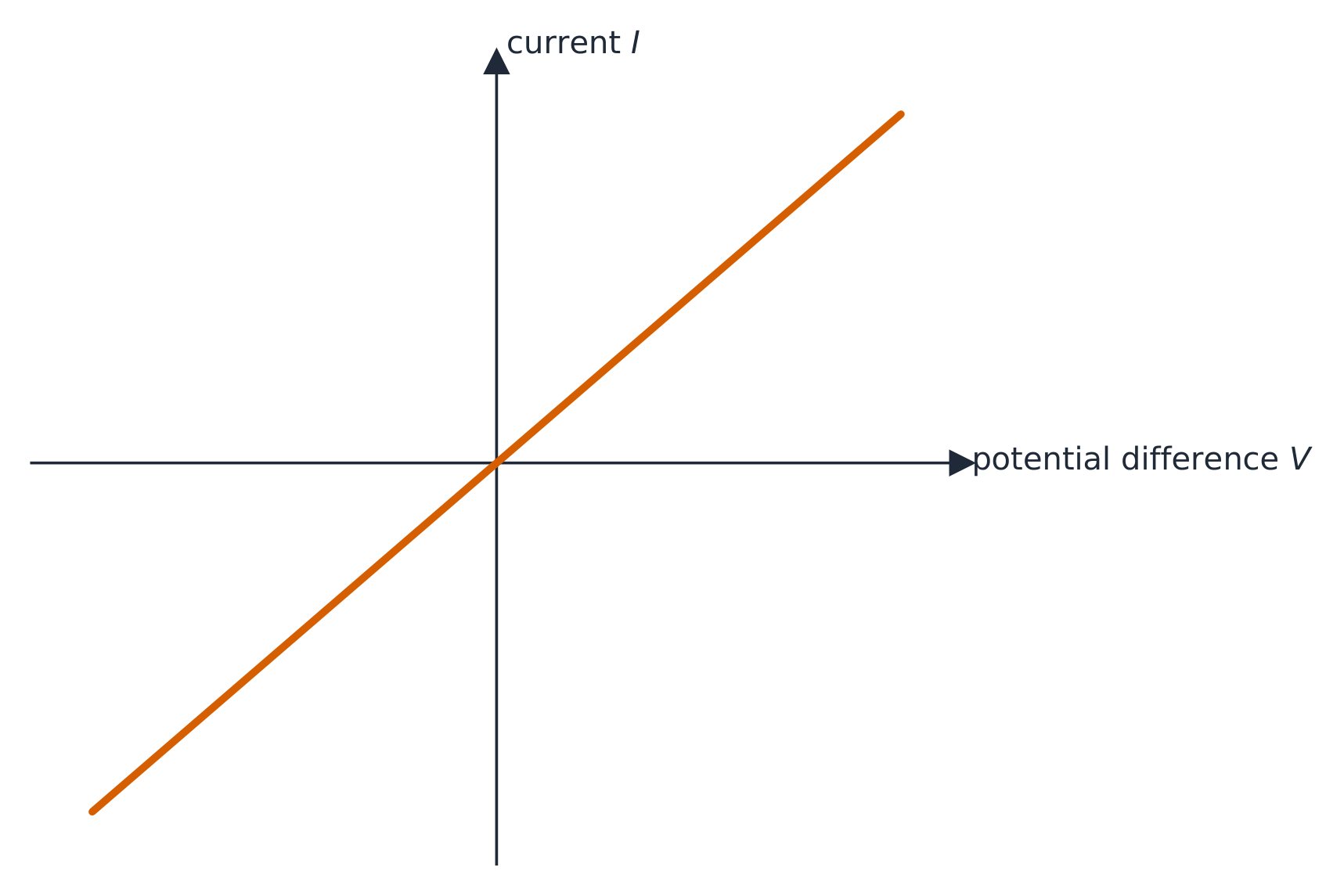
Garis I-V dari konduktor ohmik lurus melewati titik asal
Garis I-V konduktor ohmik lurus melalui titik asal

Contoh terpecahkan. Arus $2.0\ \text{A}$ mengalir melalui resistor $6.0\ \Omega$. Tegangan di atasnya adalah $V=IR=2.0\times6.0=12\ \text{V}$.

Explore · ⁨Jelajahi⁩

Apply Ohm's law · ⁨Terapkan Hukum Ohm⁩

Ohm's law $V=IR$: for a fixed resistance, current is proportional to voltage. Raise the resistance and the same voltage pushes less current. · ⁨Hukum Ohm $V=IR$: untuk hambatan tetap, arus berbanding lurus dengan tegangan. Naikkan hambatan dan tegangan yang sama mendorong arus lebih sedikit.⁩

11.4

Electric Power · ⁨Daya Listrik⁩

Syllabus · ⁨Silabus⁩
English

Learning Objective 11.4.A: Describe the transfer of energy into, out of, or within an electric circuit, in terms of power.

  • 11.4.A.1 The rate at which energy is transferred, converted, or dissipated by a circuit element depends on the current in the element and the electric potential difference across it.
    • Equation: $P = I \Delta V$
    • Equation (derived): $P = I^2 R = \dfrac{(\Delta V)^2}{R}$
  • 11.4.A.2 The brightness of a bulb increases with power, so power can be used to qualitatively predict the brightness of bulbs in a circuit.
Bahasa Indonesia

Tujuan Pembelajaran 11.4.A: Jelaskan transfer energi masuk, keluar, atau di dalam sebuah sirkuit listrik, berdasarkan daya.

  • 11.4.A.1 Laju transfer, konversi, atau pelepasan energi oleh elemen sirkuit bergantung pada arus dalam elemen tersebut dan beda potensial listrik melintasinya.
    • Persamaan: $P = I \Delta V$
    • Persamaan (turunan): $P = I^2 R = \dfrac{(\Delta V)^2}{R}$
  • 11.4.A.2 Kecerahan bohlam meningkat seiring dengan peningkatan daya, sehingga daya dapat digunakan untuk memprediksi secara kualitatif kecerahan bohlam dalam sebuah sirkuit.

Source: College Board AP Course and Exam Description · ⁨Sumber: Deskripsi Kursus dan Ujian College Board AP⁩

English

Electric power 电功率 is the rate a component converts electrical energy (to heat, light, motion):

$$P=IV=I^2R=\frac{V^2}{R}.$$
Pick the form that uses the quantities you know. A resistor's power all becomes heat.

Worked example. The $6.0\ \Omega$ resistor above, carrying $2.0\ \text{A}$, dissipates $P=I^2R=2.0^2\times6.0=24\ \text{W}$ – equivalently $P=IV=2.0\times12=24\ \text{W}$.

A light bulb 灯泡 is just a resistor that glows, and its brightness 亮度 rises with the power it dissipates. So to rank bulbs, compare their power. In a series string every bulb carries the same current, so by $P=I^2R$ the bulb with the largest resistance is brightest; wired in parallel every bulb gets the full battery voltage, so by $P=V^2/R$ the bulb with the smallest resistance is brightest.

Bahasa Indonesia

Daya listrik adalah laju komponen mengonversi energi listrik (menjadi panas, cahaya, gerakan):

$$P=IV=I^2R=\frac{V^2}{R}.$$
Pilih bentuk yang menggunakan besaran yang Anda ketahui. Daya resistor semuanya berubah menjadi panas.

Contoh terpecahkan. Resistor $6.0\ \Omega$ di atas, membawa $2.0\ \text{A}$, menyebarkan $P=I^2R=2.0^2\times6.0=24\ \text{W}$ – setara dengan $P=IV=2.0\times12=24\ \text{W}$.

Sebuah bohlam lampu hanyalah resistor yang bersinar, dan kecerahannya meningkat seiring dengan daya yang ia sebar. Jadi untuk mengurutkan bohlam, bandingkan dayanya. Dalam rangkaian seri setiap bohlam carrying arus yang sama, jadi oleh $P=I^2R$ bohlam dengan resistansi terbesar paling terang; dikoneksikan dalam paralel setiap bohlam mendapatkan tegangan baterai penuh, jadi oleh $P=V^2/R$ bohlam dengan resistansi terkecil paling terang.

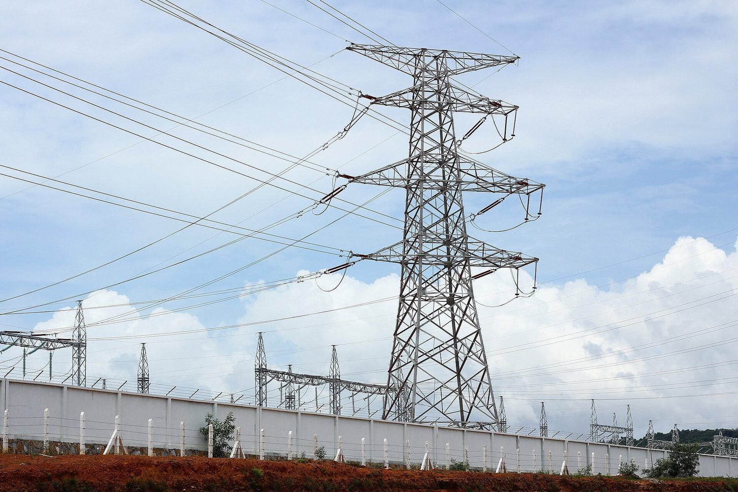
Saluran listrik bertegangan tinggi: daya listrik ditransmisikan dengan tegangan tinggi agar arus (dan kerugian I²R) tetap rendah
Saluran listrik tegangan tinggi: daya listrik ditransmisikan sebagai tegangan tinggi agar arus (dan rugi-rugi I²R) tetap rendah
Explore · ⁨Jelajahi⁩

Read an I-V characteristic · ⁨Baca karakteristik I-V⁩

Power is $P=IV$. A resistor's I-V line is straight, but a lamp curves as it heats and its resistance rises. The area under I-V relates to the energy delivered. · ⁨Daya adalah $P=IV$. Garis I-V resistor lurus, tetapi lampu melengkung saat memanas dan hambatannya naik. Area di bawah I-V berkaitan dengan energi yang disalurkan.⁩

11.5

Compound DC Circuits · ⁨Rangkaian DC Majemuk⁩

Syllabus · ⁨Silabus⁩
Learning ObjectiveEssential Knowledge

11.5.A
Describe the equivalent resistance of multiple resistors connected in a circuit.

  • 11.5.A.1 Circuit elements may be connected in series and/or in parallel.
    • 11.5.A.1.i A series connection is one in which any charge passing through one circuit element must proceed through all elements in that connection and has no other path available. The current in each element in series must be the same.
    • 11.5.A.1.ii A parallel connection is one in which charges may flow through one of two or more paths. Across each path, the potential difference is the same.
  • 11.5.A.2 A collection of resistors in a circuit may be analyzed as though it were a single resistor with an equivalent resistance $R_{\text{eq}}$.
    • 11.5.A.2.i The equivalent resistance of a set of resistors in series is the sum of the individual resistances.
      • Equation: $R_{\text{eq},s} = \sum_i R_i$
    • 11.5.A.2.ii The inverse of the equivalent resistance of a set of resistors connected in parallel is equal to the sum of the inverses of the individual resistances.
      • Equation: $\dfrac{1}{R_{\text{eq},p}} = \sum_i \dfrac{1}{R_i}$
    • 11.5.A.2.iii When resistors are connected in parallel, the number of paths available to charges increases, and the equivalent resistance of the group of resistors decreases.

11.5.B
Describe a circuit with resistive wires and a battery with internal resistance.

  • 11.5.B.1 Ideal batteries have negligible internal resistance. Ideal wires have negligible resistance.
    • 11.5.B.1.i The resistance of wires that are good conductors may normally be neglected, because their resistance is much smaller than that of other elements of a circuit.
    • 11.5.B.1.ii The resistance of wires may only be neglected if the circuit contains other elements that do have resistance.
    • 11.5.B.1.iii The potential difference a battery would supply if it were ideal is the potential difference measured across the terminals when there is no current in the battery and is sometimes referred to as its $\mathrm{emf}$ ($\varepsilon$).
  • 11.5.B.2 The internal resistance of a nonideal battery may be treated as the resistance of a resistor in series with an ideal battery and the remainder of the circuit.
  • 11.5.B.3 When there is current in a nonideal battery with internal resistance $r$, the potential difference across the terminals of the battery is reduced relative to the potential difference when there is no current in the battery.
    • Equation (derived): $\Delta V_{\text{terminal}} = \varepsilon - Ir$

11.5.C
Describe the measurement of current and potential difference in a circuit.

  • 11.5.C.1 Ammeters are used to measure current at a specific point in a circuit.
    • 11.5.C.1.i Ammeters must be connected in series with the element in which current is being measured.
    • 11.5.C.1.ii Ideal ammeters have zero resistance so that they do not affect the current in the element that they are in series with.
  • 11.5.C.2 Voltmeters are used to measure electric potential difference between two points in a circuit.
    • 11.5.C.2.i Voltmeters must be connected in parallel with the element across which potential difference is being measured.
    • 11.5.C.2.ii Ideal voltmeters have an infinite resistance so that no charge flows through them.
  • 11.5.C.3 Nonideal ammeters and voltmeters will change the properties of the circuit being measured.

Boundary statement: AP Physics 2 only expects students to qualitatively discuss how a nonideal ammeter or voltmeter will affect the results of measurements. Unless otherwise stated, all batteries, wires, and meters are assumed to be ideal.

Boundary statement: Circuits with batteries of different potential differences connected in parallel will not be assessed.

Source: College Board AP Course and Exam Description · ⁨Sumber: Deskripsi Kursus dan Ujian College Board AP⁩

English

Combine resistors to find an equivalent resistance 等效电阻:

  • Series: $R_{\text{eq}}=R_1+R_2+\cdots$ (resistances add).
  • Parallel: $\dfrac{1}{R_{\text{eq}}}=\dfrac{1}{R_1}+\dfrac{1}{R_2}+\cdots$ (the total is less than the smallest).

Reduce the network step by step to find the total current from the battery, then work back to each element.

Worked example. A $12\ \text{V}$ battery drives a $4.0\ \Omega$ and a $12\ \Omega$ resistor in parallel. First combine them: $\dfrac{1}{R_{\text{eq}}}=\dfrac14+\dfrac{1}{12}=\dfrac{4}{12}\Rightarrow R_{\text{eq}}=3.0\ \Omega$. The total current from the battery is $I=\dfrac{V}{R_{\text{eq}}}=\dfrac{12}{3.0}=4.0\ \text{A}$, which splits so that the smaller resistor carries the larger share ($3.0\ \text{A}$ through the $4\ \Omega$, $1.0\ \text{A}$ through the $12\ \Omega$).

Bahasa Indonesia

Gabungkan resistor untuk menemukan resistansi ekuivalen:

Resistor dalam seri dijumlahkan menjadi satu hambatan pengganti
  • Seri: $R_{\text{eq}}=R_1+R_2+\cdots$ (hambatan dijumlahkan).
  • Paralel: $\dfrac{1}{R_{\text{eq}}}=\dfrac{1}{R_1}+\dfrac{1}{R_2}+\cdots$ (totalnya lebih kecil dari yang terkecil).

Sederhanakan rangkaian langkah demi langkah untuk mencari arus total dari baterai, lalu kerjakan mundur ke setiap elemen.

Contoh soal. Sebuah baterai $12\ \text{V}$ menggerakkan resistor $4.0\ \Omega$ dan $12\ \Omega$ secara paralel. Pertama gabungkan: $\dfrac{1}{R_{\text{eq}}}=\dfrac14+\dfrac{1}{12}=\dfrac{4}{12}\Rightarrow R_{\text{eq}}=3.0\ \Omega$. Arus total dari baterai adalah $I=\dfrac{V}{R_{\text{eq}}}=\dfrac{12}{3.0}=4.0\ \text{A}$, yang kemudian terbagi sehingga resistor yang lebih kecil membawa bagian arus yang lebih besar ($3.0\ \text{A}$ melalui $4\ \Omega$, $1.0\ \text{A}$ melalui $12\ \Omega$).

11.5

Measuring Current and Voltage · ⁨Mengukur Arus dan Tegangan⁩

Syllabus · ⁨Silabus⁩
Learning ObjectiveEssential Knowledge

11.5.A
Describe the equivalent resistance of multiple resistors connected in a circuit.

  • 11.5.A.1 Circuit elements may be connected in series and/or in parallel.
    • 11.5.A.1.i A series connection is one in which any charge passing through one circuit element must proceed through all elements in that connection and has no other path available. The current in each element in series must be the same.
    • 11.5.A.1.ii A parallel connection is one in which charges may flow through one of two or more paths. Across each path, the potential difference is the same.
  • 11.5.A.2 A collection of resistors in a circuit may be analyzed as though it were a single resistor with an equivalent resistance $R_{\text{eq}}$.
    • 11.5.A.2.i The equivalent resistance of a set of resistors in series is the sum of the individual resistances.
      • Equation: $R_{\text{eq},s} = \sum_i R_i$
    • 11.5.A.2.ii The inverse of the equivalent resistance of a set of resistors connected in parallel is equal to the sum of the inverses of the individual resistances.
      • Equation: $\dfrac{1}{R_{\text{eq},p}} = \sum_i \dfrac{1}{R_i}$
    • 11.5.A.2.iii When resistors are connected in parallel, the number of paths available to charges increases, and the equivalent resistance of the group of resistors decreases.

11.5.B
Describe a circuit with resistive wires and a battery with internal resistance.

  • 11.5.B.1 Ideal batteries have negligible internal resistance. Ideal wires have negligible resistance.
    • 11.5.B.1.i The resistance of wires that are good conductors may normally be neglected, because their resistance is much smaller than that of other elements of a circuit.
    • 11.5.B.1.ii The resistance of wires may only be neglected if the circuit contains other elements that do have resistance.
    • 11.5.B.1.iii The potential difference a battery would supply if it were ideal is the potential difference measured across the terminals when there is no current in the battery and is sometimes referred to as its $\mathrm{emf}$ ($\varepsilon$).
  • 11.5.B.2 The internal resistance of a nonideal battery may be treated as the resistance of a resistor in series with an ideal battery and the remainder of the circuit.
  • 11.5.B.3 When there is current in a nonideal battery with internal resistance $r$, the potential difference across the terminals of the battery is reduced relative to the potential difference when there is no current in the battery.
    • Equation (derived): $\Delta V_{\text{terminal}} = \varepsilon - Ir$

11.5.C
Describe the measurement of current and potential difference in a circuit.

  • 11.5.C.1 Ammeters are used to measure current at a specific point in a circuit.
    • 11.5.C.1.i Ammeters must be connected in series with the element in which current is being measured.
    • 11.5.C.1.ii Ideal ammeters have zero resistance so that they do not affect the current in the element that they are in series with.
  • 11.5.C.2 Voltmeters are used to measure electric potential difference between two points in a circuit.
    • 11.5.C.2.i Voltmeters must be connected in parallel with the element across which potential difference is being measured.
    • 11.5.C.2.ii Ideal voltmeters have an infinite resistance so that no charge flows through them.
  • 11.5.C.3 Nonideal ammeters and voltmeters will change the properties of the circuit being measured.

Boundary statement: AP Physics 2 only expects students to qualitatively discuss how a nonideal ammeter or voltmeter will affect the results of measurements. Unless otherwise stated, all batteries, wires, and meters are assumed to be ideal.

Boundary statement: Circuits with batteries of different potential differences connected in parallel will not be assessed.

Source: College Board AP Course and Exam Description · ⁨Sumber: Deskripsi Kursus dan Ujian College Board AP⁩

English

Two meters read a circuit. An ammeter 电流表 measures the current at a point, so it must be wired in series – the current you want to measure has to flow through it. A voltmeter 电压表 measures the potential difference between two points, so it is wired in parallel, bridging across the component whose voltage you want.

For a meter to read the true value it must barely disturb the circuit:

  • an ideal ammeter has zero resistance, so putting it in series does not reduce the current it reads;
  • an ideal voltmeter has infinite resistance, so almost no current is diverted through it.

A real, nonideal 非理想 meter is imperfect: a real ammeter has a small resistance (it slightly lowers the current), and a real voltmeter lets a little current leak through (it slightly lowers the voltage it reads). So connecting any meter changes, a little, the very quantity it is measuring.

Bahasa Indonesia

Dua alat ukur membaca suatu rangkaian. Ammeter mengukur arus pada suatu titik, sehingga harus dirangkai seri – arus yang ingin diukur harus mengalir melewati alat tersebut. Voltmeter mengukur beda potensial antara dua titik, sehingga dirangkai paralel, melintasi komponen whose tegangannya ingin Anda ukur.

Agar sebuah alat ukur dapat menampilkan nilai yang benar, alat itu hampir tidak boleh mengganggu rangkaian:

  • amperemeter ideal memiliki hambatan nol, sehingga memasukkannya secara seri tidak mengurangi arus yang terbaca;
  • voltmeter ideal memiliki hambatan tak hingga, sehingga hampir tidak ada arus yang dialihkan melalui alat tersebut.

Alat ukur nyata yang nonideal tidak sempurna: amperemeter nyata memiliki hambatan kecil (sedikit menurunkan arus), dan voltmeter nyata membiarkan sedikit arus bocor (sedikit menurunkan tegangan yang terbaca). Jadi, menghubungkan alat ukur apa pun akan mengubah, sedikit sekali, besaran yang sedang diukurnya.

Vocabulary · ⁨Kosa kata⁩ Train · ⁨Latih⁩
English Bahasa Indonesia
ammeter/ˈæmiːtə/ amperemeter
voltmeter/ˈvəʊltmiːtə/ voltmeter
nonideal/ˌnɒnaɪˈdɪəl/ Nonideal
Kirchhoff's loop rule/ˈkɜːkhɒfs luːp ruːl/ Aturan loop Kirchhoff
Kirchhoff's junction rule/ˈkɜːkhɒfs ˈdʒʌŋkʃn ruːl/ Aturan titik simpul Kirchhoff
RC circuit/ˌɑː ˈsiː ˈsɜːkɪt/ sirkuit RC
11.6

Kirchhoff's Loop Rule · ⁨Aturan Loop Kirchhoff⁩

Syllabus · ⁨Silabus⁩
English

Learning Objective 11.6.A: Describe a circuit or elements of a circuit by applying Kirchhoff's loop rule.

  • 11.6.A.1 Energy changes in simple electrical circuits may be represented in terms of charges moving through electric potential differences within circuit elements.
    • Equation: $\Delta U_E = q \Delta V$
  • 11.6.A.2 Kirchhoff's loop rule is a consequence of the conservation of energy.
  • 11.6.A.3 Kirchhoff's loop rule states that the sum of potential differences across all circuit elements in a single closed loop must equal zero.
    • Equation: $\sum \Delta V = 0$
  • 11.6.A.4 The values of electric potential at points in a circuit can be represented by a graph of electric potential as a function of position within a loop.
Bahasa Indonesia

Tujuan Pembelajaran 11.6.A: Deskripsikan sebuah sirkuit atau elemen-elemen sirkuit dengan menerapkan aturan loop Kirchhoff.

  • 11.6.A.1 Perubahan energi dalam sirkuit listrik sederhana dapat direpresentasikan dalam istilah muatan yang bergerak melalui beda potensial listrik di dalam elemen-elemen sirkuit.
    • Persamaan: $\Delta U_E = q \Delta V$
  • 11.6.A.2 Aturan loop Kirchhoff merupakan konsekuensi dari kekekalan energi.
  • 11.6.A.3 Aturan loop Kirchhoff menyatakan bahwa jumlah beda potensial di seluruh elemen sirkuit dalam satu loop tertutup harus sama dengan nol.
    • Persamaan: $\sum \Delta V = 0$
  • 11.6.A.4 Nilai-nilai potensial listrik pada titik-titik dalam sirkuit dapat direpresentasikan oleh grafik potensial listrik sebagai fungsi posisi dalam sebuah loop.

Source: College Board AP Course and Exam Description · ⁨Sumber: Deskripsi Kursus dan Ujian College Board AP⁩

English

Kirchhoff's loop rule 基尔霍夫电压定律 (energy conservation): around any closed loop, the voltage gains and drops sum to zero. Add the battery's emf and subtract each $IR$ drop as you go around. This gives one equation per independent loop.

Bahasa Indonesia

Aturan loop Kirchhoff (kekekalan energi): di sekitar loop tertutup mana pun, penjumlahan kenaikan dan penurunan tegangan bernilai nol. Tambahkan emf baterai dan kurangi setiap penurunan $IR$ saat bergerak mengelilinginya. Ini memberikan satu persamaan per loop independen.

11.7

Kirchhoff's Junction Rule · ⁨Aturan Simpul Kirchhoff⁩

Syllabus · ⁨Silabus⁩
English

Learning Objective 11.7.A: Describe a circuit or elements of a circuit by applying Kirchhoff's junction rule.

  • 11.7.A.1 Kirchhoff's junction rule is a consequence of the conservation of electric charge.
  • 11.7.A.2 Kirchhoff's junction rule states that the total amount of charge entering a junction per unit time must equal the total amount of charge exiting that junction per unit time.
    • Equation: $\sum I_{\text{in}} = \sum I_{\text{out}}$
Bahasa Indonesia

Tujuan Pembelajaran 11.7.A: Deskripsikan sebuah sirkuit atau elemen-elemen sirkuit dengan menerapkan aturan titik simpul Kirchhoff.

  • 11.7.A.1 Aturan titik simpul Kirchhoff merupakan konsekuensi dari kekekalan muatan listrik.
  • 11.7.A.2 Aturan titik simpul Kirchhoff menyatakan bahwa total jumlah muatan yang masuk ke sebuah titik simpul per satuan waktu harus sama dengan total jumlah muatan yang keluar dari titik simpul tersebut per satuan waktu.
    • Persamaan: $\sum I_{\text{in}} = \sum I_{\text{out}}$

Source: College Board AP Course and Exam Description · ⁨Sumber: Deskripsi Kursus dan Ujian College Board AP⁩

English

Kirchhoff's junction rule 基尔霍夫电流定律 (charge conservation): the total current into any junction equals the total current out. Together with the loop rule, it lets you solve any multi-loop circuit for its unknown currents.

Bahasa Indonesia

Aturan simpul Kirchhoff (kekekalan muatan): total arus masuk ke suatu simpul sama dengan total arus keluar. Bersama dengan aturan loop, hal ini memungkinkan Anda menyelesaikan rangkaian multi-loop apa pun untuk mencari arus-arus yang belum diketahui.

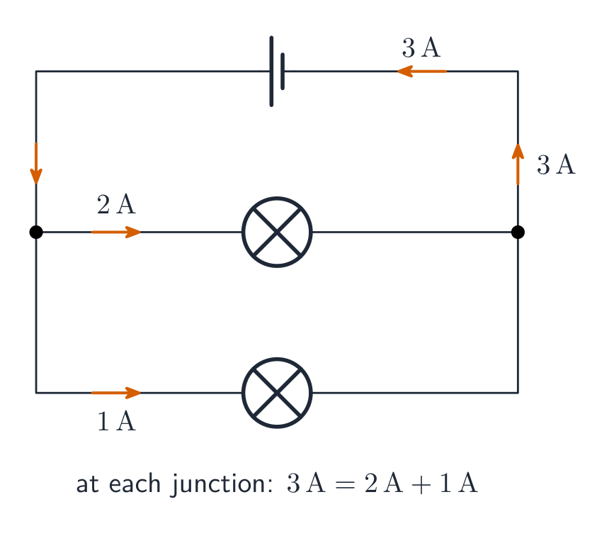
Arus terbagi di simpul: apa yang masuk sama dengan apa yang keluar
11.8

RC Circuits · ⁨Rangkaian RC⁩

Syllabus · ⁨Silabus⁩
English

Learning Objective 11.8.A: Describe the equivalent capacitance of multiple capacitors.

  • 11.8.A.1 A collection of capacitors in a circuit may be analyzed as though it were a single capacitor with an equivalent capacitance $C_{\text{eq}}$.
    • 11.8.A.1.i The inverse of the equivalent capacitance of a set of capacitors connected in series is equal to the sum of the inverses of the individual capacitances.
      • Equation: $\dfrac{1}{C_{\text{eq},s}} = \sum_i \dfrac{1}{C_i}$
    • 11.8.A.1.ii The equivalent capacitance of a set of capacitors in series is less than the capacitance of the smallest capacitor.
    • 11.8.A.1.iii The equivalent capacitance of a set of capacitors in parallel is the sum of the individual capacitances.
      • Equation: $C_{\text{eq},p} = \sum_i C_i$
  • 11.8.A.2 As a result of conservation of charge, each of the capacitors in series must have the same magnitude of charge on each plate.

Learning Objective 11.8.B: Describe the behavior of a circuit containing combinations of resistors and capacitors.

  • 11.8.B.1 The time constant $\tau$ is a significant feature of an RC circuit.
    • 11.8.B.1.i The time constant of an RC circuit is a measure of how quickly the capacitor will charge or discharge and is defined as $\tau = R_{\text{eq}} C_{\text{eq}}$.
    • 11.8.B.1.ii For a charging capacitor, the time constant represents the time required for the capacitor's charge to increase from zero to approximately 63 percent of its final asymptotic value.
    • 11.8.B.1.iii For a discharging capacitor, the time constant represents the time required for the capacitor's charge to decrease from fully charged to approximately 37 percent of its initial value.
  • 11.8.B.2 The potential difference across a capacitor and the current in the branch of the circuit containing the capacitor each change over time as the capacitor charges and discharges, but both will reach a steady state after a long time interval.
    • 11.8.B.2.i Immediately after being placed in a circuit, an uncharged capacitor acts like a wire, and charge can easily flow to or from the plates of the capacitor.
    • 11.8.B.2.ii As a capacitor charges, changes to the potential difference across the capacitor affect the charge on the plates of the capacitor, the current circuit branch in which the capacitor is located, and the electric potential energy stored in the capacitor.
    • 11.8.B.2.iii The potential difference across a capacitor, the current in the circuit branch in which the capacitor is located, and the electric potential energy stored in the capacitor all change with respect to time and asymptotically approach steady state conditions.
    • 11.8.B.2.iv After a long time, a charging capacitor approaches a state of being fully charged, reaching a maximum potential difference at which there is zero current in the circuit branch in which the capacitor is located.
    • 11.8.B.2.v Immediately after a charged capacitor begins discharging, the amount of charge on the capacitor plates and the energy stored in the capacitor begin to decrease.
    • 11.8.B.2.vi As a capacitor discharges, the amount of charge on the capacitor, the potential difference across the capacitor, and the current in the circuit branch in which the capacitor is located all decrease until a steady state is reached.
    • 11.8.B.2.vii After either charging or discharging for times much greater than the time constant, the capacitor and the relevant circuit branch may be modeled using steady-state conditions.

Boundary statement: Descriptions of charging/discharging RC circuits in AP Physics 2 are limited to qualitative descriptions and representations. While students should be able to mathematically describe initial and final states of RC circuits, students are not expected to mathematically model these behaviors with respect to time.

Bahasa Indonesia

Tujuan Pembelajaran 11.8.A: Deskripsikan kapasitansi ekuivalen dari beberapa kapasitor.

  • 11.8.A.1 Kumpulan kapasitor dalam suatu sirkuit dapat dianalisis seolah-olah merupakan sebuah kapasitor tunggal dengan kapasitansi ekuivalen $C_{\text{eq}}$.
    • 11.8.A.1.i Kebalikan dari kapasitansi ekuivalen dari sekumpulan kapasitor yang dirangkai seri sama dengan jumlah dari kebalikan dari kapasitansi-kapasitansi individual.
      • Persamaan: $\dfrac{1}{C_{\text{eq},s}} = \sum_i \dfrac{1}{C_i}$
    • 11.8.A.1.ii Kapasitansi ekuivalen dari sekumpulan kapasitor yang dirangkai seri kurang dari kapasitansi kapasitor terkecil.
    • 11.8.A.1.iii Kapasitansi ekuivalen dari sekumpulan kapasitor yang dirangkai paralel adalah jumlah dari kapasitansi-kapasitansi individual.
      • Persamaan: $C_{\text{eq},p} = \sum_i C_i$
  • 11.8.A.2 Akibat dari kekekalan muatan, masing-masing kapasitor dalam rangkaian seri harus memiliki besaran muatan yang sama pada setiap pelatnya.

Tujuan Pembelajaran 11.8.B: Deskripsikan perilaku sirkuit yang mengandung kombinasi resistor dan kapasitor.

  • 11.8.B.1 Konstanta waktu $\tau$ adalah fitur penting dari sirkuit RC.
    • 11.8.B.1.i Konstanta waktu dari sirkuit RC merupakan ukuran seberapa cepat kapasitor akan mengisi atau mengosongkan muatannya dan didefinisikan sebagai $\tau = R_{\text{eq}} C_{\text{eq}}$.
    • 11.8.B.1.ii Untuk kapasitor yang sedang mengisi, konstanta waktu mewakili waktu yang diperlukan agar muatan kapasitor meningkat dari nol menjadi sekitar 63 persen dari nilai asimtotik akhirnya.
    • 11.8.B.1.iii Untuk kapasitor yang sedang mengosongkan, konstanta waktu mewakili waktu yang diperlukan agar muatan kapasitor menurun dari kondisi terisi penuh menjadi sekitar 37 persen dari nilai awalnya.
  • 11.8.B.2 Beda potensial pada kapasitor dan arus dalam cabang rangkaian yang mengandung kapasitor masing-masing berubah seiring berjalannya waktu saat kapasitor mengisi dan mengosongkan, namun keduanya akan mencapai keadaan tunak setelah selang waktu yang lama.
    • 11.8.B.2.i Segera setelah dimasukkan ke dalam rangkaian, kapasitor yang belum bermuatan bertindak seperti kawat, dan muatan dapat mengalir dengan mudah masuk atau keluar dari pelat kapasitor.
    • 11.8.B.2.ii Saat kapasitor mengisi, perubahan beda potensial pada kapasitor memengaruhi muatan pada pelat kapasitor, arus dalam cabang rangkaian tempat kapasitor berada, dan energi potensial listrik yang tersimpan di dalamnya.
    • 11.8.B.2.iii Beda potensial pada kapasitor, arus dalam cabang rangkaian tempat kapasitor berada, dan energi potensial listrik yang tersimpan di dalamnya semuanya berubah terhadap waktu dan secara asimtotik mendekati kondisi keadaan tunak.
    • 11.8.B.2.iv Setelah selang waktu yang lama, kapasitor yang sedang mengisi mendekati keadaan terisi penuh, mencapai beda potensial maksimum di mana tidak ada arus dalam cabang rangkaian tempat kapasitor berada.
    • 11.8.B.2.v Segera setelah kapasitor yang bermuatan mulai mengosongkan, jumlah muatan pada pelat kapasitor dan energi yang tersimpan di dalamnya mulai berkurang.
    • 11.8.B.2.vi Saat kapasitor mengosongkan, jumlah muatan pada kapasitor, beda potensial pada kapasitor, dan arus dalam cabang rangkaian tempat kapasitor berada semuanya berkurang hingga keadaan tunak tercapai.
    • 11.8.B.2.vii Setelah pengisian atau pengosongan selama waktu yang jauh lebih besar daripada konstanta waktu, kapasitor dan cabang rangkaian yang relevan dapat dimodelkan menggunakan kondisi keadaan tunak.

Pernyataan Batas: Deskripsi tentang rangkaian RC pengisian/pengosongan dalam AP Physics 2 dibatasi pada deskripsi kualitatif dan representasi. Meskipun siswa harus mampu mendeskripsikan secara matematis keadaan awal dan akhir rangkaian RC, siswa tidak diharapkan untuk memodelkan perilaku ini secara matematis terhadap waktu.

Source: College Board AP Course and Exam Description · ⁨Sumber: Deskripsi Kursus dan Ujian College Board AP⁩

English
Charging a capacitor (RC)

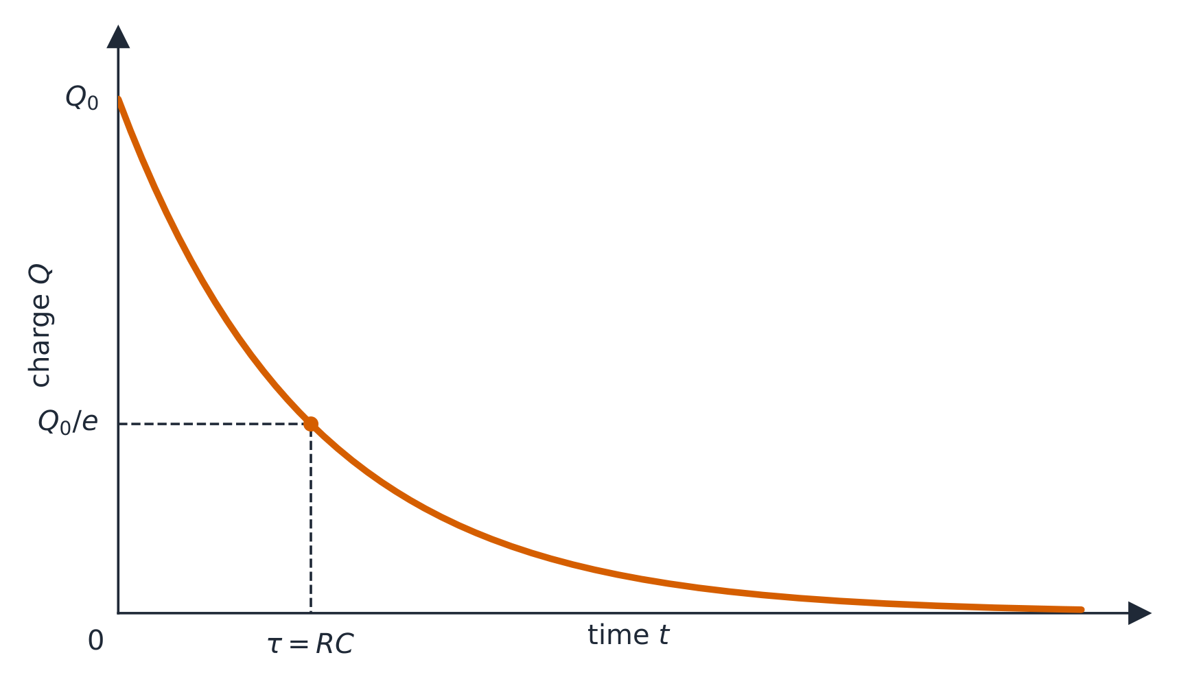
An RC circuit RC电路 contains a resistor and a capacitor. When charging, the capacitor's voltage rises and the current falls, both exponentially, over a characteristic time $\tau=RC$. Key limits: at the first instant the uncharged capacitor acts like a plain wire (maximum current); after a long time it is fully charged and blocks current (acts like a break).

Worked example. For $R=10\ \text{k}\Omega$ and $C=100\ \mu\text{F}$, the time constant is $\tau=RC=(10\times10^{3})(100\times10^{-6})=1.0\ \text{s}$. After one time constant the capacitor reaches about $63\%$ of the supply voltage; after about $5\tau$ it is essentially fully charged.

Bahasa Indonesia
Mengisi kapasitor (RC)

Sebuah rangkaian RC RC mengandung resistor dan kapasitor. Saat pengisian, tegangan kapasitor naik dan arus turun, keduanya secara eksponensial, selama waktu karakteristik $\tau=RC$. Batasan utama: pada detik pertama kapasitor yang belum terisi bertindak seperti kawat biasa (arus maksimum); setelah waktu yang lama ia terisi penuh dan memblokir arus (berperilaku seperti pemutus).

Muatan pada kapasitor meluruh secara eksponensial saat melepaskan muatan

Contoh soal. Untuk $R=10\ \text{k}\Omega$ dan $C=100\ \mu\text{F}$, konstanta waktu adalah $\tau=RC=(10\times10^{3})(100\times10^{-6})=1.0\ \text{s}$. Setelah satu konstanta waktu kapasitor mencapai sekitar $63\%$ dari tegangan suplai; setelah sekitar $5\tau$ ia pada dasarnya terisi penuh.

11.8

Exam tips · ⁨Tips ujian⁩

English
  • In series the current is the same throughout; in parallel the voltage is the same across each branch — never mix these up.
  • Combine resistors: series add; parallel $1/R_{\text{eq}}=\sum 1/R_i$ (the total is less than the smallest).
  • Apply Kirchhoff's rules: junction (current in = current out, charge conserved) and loop (voltages sum to zero, energy conserved).
  • Pick the power form that fits your knowns: $P=IV=I^2R=V^2/R$.
  • An ammeter goes in series (ideal: zero resistance); a voltmeter goes in parallel (ideal: infinite resistance). A real meter slightly disturbs the circuit it measures.
  • A bulb is brighter when it dissipates more power – in series the biggest resistance ($I^2R$) glows brightest; in parallel the smallest ($V^2/R$) does.
  • In an RC circuit the capacitor acts like a plain wire the instant it starts charging and like a break once fully charged.
Bahasa Indonesia
  • Dalam seri arusnya sama di seluruh tempat; dalam paralel tegangannya sama di setiap cabang – jangan pernah mencampur keduanya.
  • Gabungkan resistor: seri ditambah; paralel $1/R_{\text{eq}}=\sum 1/R_i$ (totalnya lebih kecil dari yang terkecil).
  • Terapkan aturan Kirchhoff: simpul (arus masuk = arus keluar, muatan kekal) dan loop (tegangan menjumlahkan nol, energi kekal).
  • Pilih bentuk daya yang sesuai dengan data yang Anda miliki: $P=IV=I^2R=V^2/R$.
  • Ammeter dipasang secara seri (ideal: hambatan nol); voltmeter dipasang secara paralel (ideal: hambatan tak hingga). Alat ukur nyata sedikit mengganggu rangkaian yang diukurnya.
  • Bohlam menyala lebih terang ketika menyerap lebih banyak daya – dalam seri hambatan terbesar ($I^2R$) menyala paling terang; dalam paralel yang terkecil ($V^2/R$) yang melakukan hal itu.
  • Dalam rangkaian RC kapasitor bertindak seperti kawat biasa pada detik pertama mulai mengisi dan seperti pemutus setelah terisi penuh.

Interactive lessons on this topic · ⁨Pelajaran interaktif untuk topik ini⁩

Work through it step by step, with instant-check exercises. · ⁨Kerjakan langkah demi langkah, dengan latihan pengecekan instan.⁩

Past Papers · ⁨Soal-Soil Masa Lalu⁩

More topics in AP Physics 2 · ⁨AP Fisika 2⁩ · ⁨Topik lain dalam AP Physics 2 · ⁨AP Fisika 2⁩⁩

Log in or create account · ⁨Masuk atau buat akun⁩

IGCSE, A-Level & AP