ซิลิกอนบริสุทธิ์นำไฟฟ้าได้ไม่ดี; การเจือสารเพิ่มตัวพาประจุ — Donor ทำให้เกิดชนิด n
(electrons), acceptors make p-type (holes). A pn junction PN conducts one
วิธี: การเบี่ยงเบนไปข้างหน้า (ด้าน p เป็นบวก) อนุญาตให้กระแสไหลแบบเอกซ์โพเนนเชียล; การเบี่ยงเบนย้อนกลับ
ความเอียงขยายเขตการขาดแคลนประจุและกั้นกระแส
ไดโอดมีลำดับของโมเดล — เลือกใช้ตามโจทย์คำถาม:
แบบอุดมคติ (Ideal): 0 V เมื่อมีการนำไฟฟ้า, เปิดวงจรเมื่อไม่ทำงาน
แบบ Drop คงที่ (Constant-drop): 0.7 V เมื่อมีการนำไฟฟ้า (ซิลิกอน)
แบบเส้นแบ่งช่วง (Piecewise-linear): 0.7 V + ความต้านทาน Slope $r_{d} = nV_{T}/I_{D}$
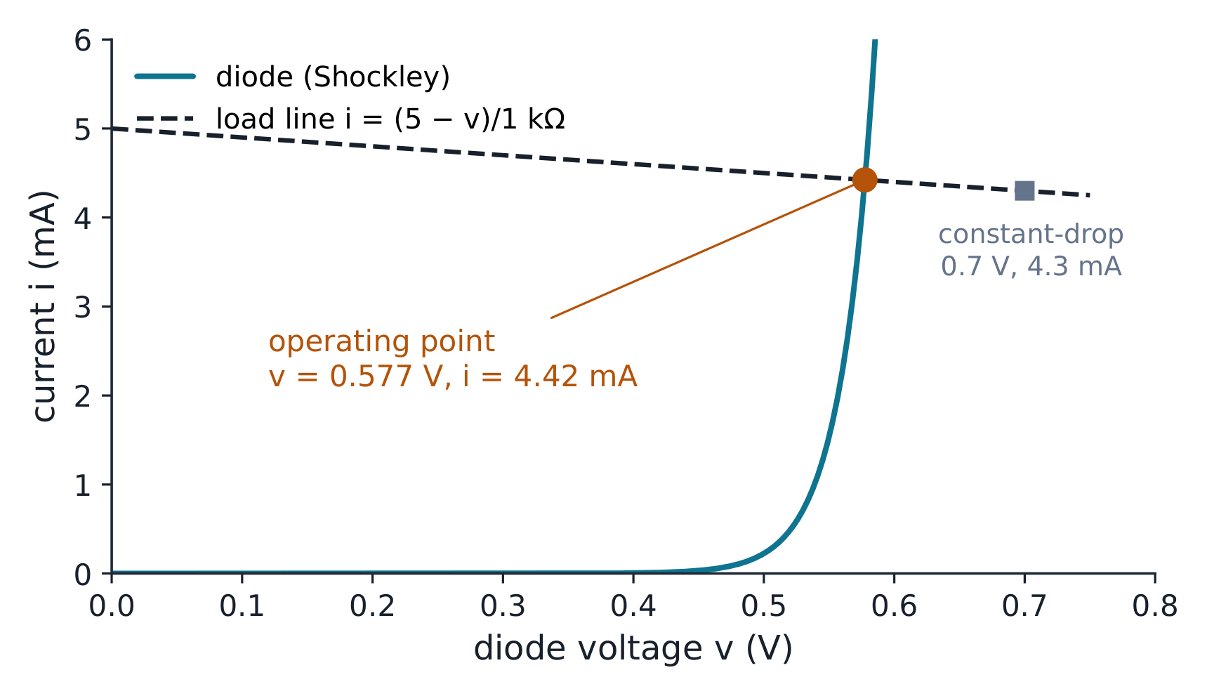
The 5 V and 1 kΩ circuit gives about 0.5775 V and 4.42 mA with Shockley, compared with 4.3 mA for the 0.7 V model. Change the source or resistor, then compare a +0.1 V source change with the local dynamic-resistance prediction. A low-supply case shows why a fixed drop can fail.
5.2
เครื่องเปลี่ยนกระแสสลับเป็นกระแสตรงและแหล่งจ่าย DC
For the 12 V to 5.1 V example, 560 Ω leaves 2.32 mA for the zener at a 10 mA load and about 63 mW at no load. With an illustrative 100 mW power rating, compare the lower power-bound resistance with the 575 Ω upper current bound. A smaller resistor can exceed the power rating; a larger one can lose regulation.
Keep the worked 12 V, 68 kΩ/12 kΩ divider, 2.2 kΩ collector resistor and 1 kΩ emitter resistor. Compare β = 100 and 200, then remove the emitter resistor or stiffen the divider. Check the active assumption before accepting any current or voltage as a Q-point.
The worked 3 V gate gives a valid saturation point at 1.125 mA and 6.625 V. At a 5 V gate the saturation assumption fails, and the triode equation has two algebraic roots. Only 1 V and 3 mA satisfies the assumed region; the larger positive root is rejected.
Start with the worked 0.99 mA BJT bias and recover gm about 38.1 mS, input resistance about 2.6 kΩ and bypassed gain about −80. Widen the input excursion to see the curved current law leave its tangent. Switch device at the same bias current to compare gm fairly, then select the MOSFET worked bias of 1.125 mA for gm 1.5 mS and gain −4.5.
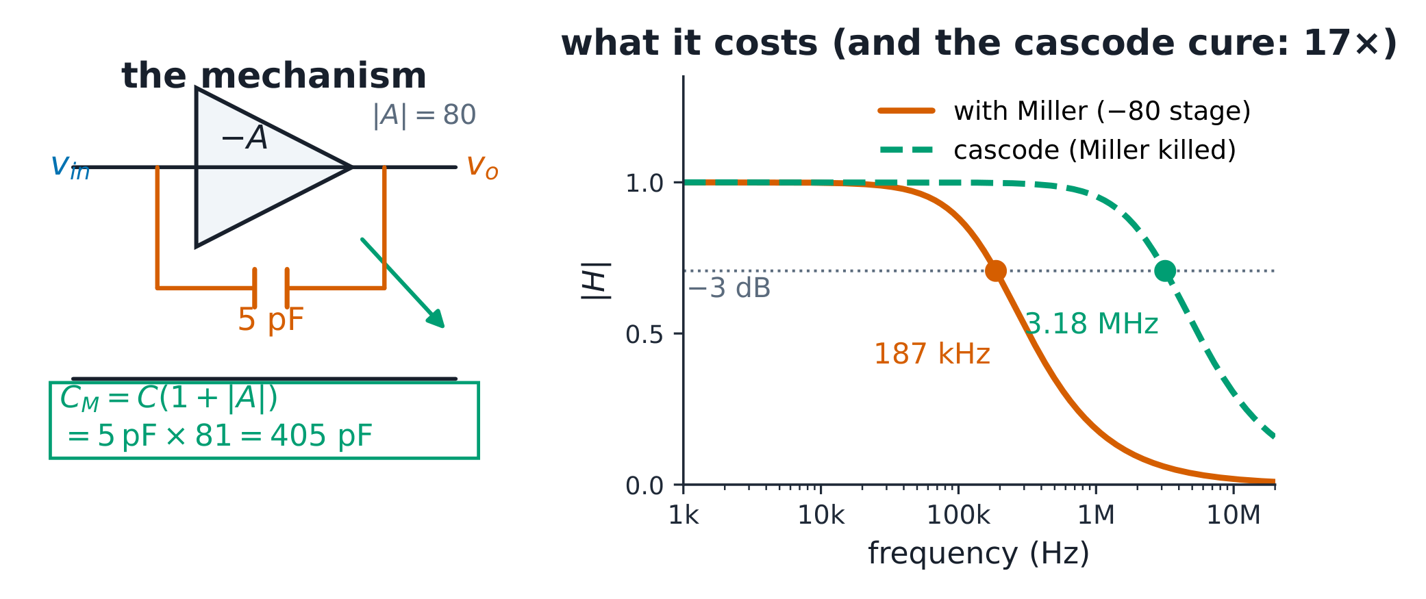
Miller moves the upper corner; cascades narrow both ends
$C_M=C(1+A),\quad f_H\approx\frac{1}{2\pi R C_{total}}$
Start with the worked gain magnitude 80, 5 pF feedback capacitor and 20 pF stray capacitance. Miller gives 425 pF in total and a high corner near 187 kHz. Suppress multiplication with the cascode idealisation to reach about 3.18 MHz. Then compare two buffered stages with one and probe the chain’s own half-power edge near 120 kHz. Changing the coupling capacitor moves the low corner independently.