Skip to content

Digital Logic Design

University Electrical Engineering · Topic 3

3.1

What this course is, and how to use it

This is the third course in University Electrical Engineering: digital logic design 数字逻辑设计 — how bits are represented, combined, stored and timed inside every computer. It needs no prior electronics: the primitives are two voltage levels and a handful of gates.

  • Unit 3.1 builds the number systems: binary, hexadecimal, two's complement.
  • Units 3.2–3.3 combine logic: Boolean algebra, Karnaugh maps, combinational blocks.
  • Units 3.4–3.5 add time: latches, flip-flops, and clocked state machines.
  • Unit 3.6 registers the patterns: counters, shift registers, memory.
  • Unit 3.7 describes them in HDL and verifies with testbenches.

Each unit opens with a story, shows a picture before the formal idea, defines terms precisely, works two escalating examples whose arithmetic is machine-verified, names the classic mistakes, and closes with a three-line summary. The checking habit of this course: every Boolean answer is verified by exhaustive evaluation — a 3-input function has only 8 rows, so check all of them, either by hand on a truth table or by a loop in the sandbox.

Vocabulary Train
English
digital logic design/ˈdɪdʒɪtl ˈlɒdʒɪk dɪˈzaɪn/
3.1

Number representations and codes

A thermostat displays 22.5 °C, but the microcontroller behind it holds only bits. How does 22.5 become a bit pattern a machine can add, compare and store? Unit 3.1 is that translation, in both directions.

Computers store numbers in binary 二进制 (base 2). Conversion is systematic: divide by 2 for integers (collect remainders), multiply by 2 for fractions. Hexadecimal 十六进制 (base 16) is binary's shorthand — each hex digit is exactly 4 bits: $0xB = 1011$.

An 8-bit register box divided into bit positions with weights 128, 64, 32, 16, 8, 4, 2, 1; the pattern 10011100 marked with weights 128+16+8+4 = 156
Weights on the bits: read the pattern by adding the weights under each 1

Deriving two's complement. We want an encoding where subtraction reuses the adder: $a - b = a + (b\text{ negated})$ must hold modulo $2^N$. The additive inverse of $b$ modulo $2^N$ is $2^N - b = (2^N - 1 - b) + 1$ — and $2^N - 1 - b$ is exactly "every bit of $b$ inverted" (each 1-weight flips to 0 and back). So negate = invert + 1, and the derivation is the proof that addition works unchanged.

Two's complement 二进制补码 represents signed integers in N bits: invert every bit and add 1 to negate. In 8 bits, $-5$ is $\overline{00000101}$ plus 1, which is $11111011$. The range 范围 runs from $-2^{N-1}$ up to $+2^{N-1}-1$ — that is −128 to +127 in 8 bits. Overflow 溢出 occurs when the result leaves the range: adding two positives and reading a negative (or vice versa) is the sign-based detection rule — carry out of the MSB is not overflow; carry out differing from carry into the MSB is.

Worked example 1 (convert and check). Convert 156 to binary: $156 = 128 + 16 + 8 + 4 = 10011100$. Check by re-adding the weights: $128 + 16 + 8 + 4 = 156$ ✓. The same number in hex: group the bits in fours from the right — $1001\ 1100 = 0x9C$ ✓. And the fraction 0.625: multiply by 2 → 1.25 (1), 0.25×2 → 0.5 (0), 0.5×2 → 1.0 (1): $0.625 = 0.101_2$ ✓ ($0.5 + 0.125$).

Worked example 2 (negative numbers and overflow, escalated). Encode −100 in 8 bits: $100 = 01100100$; invert $10011011$; add 1 → $10011100$. Check by decoding: as unsigned that is 156, and $156 - 256 = -100$ ✓. Now the overflow case: $100 + 50 = 150 > 127$, so 8-bit signed cannot hold it — the bits compute $10010110$, which decodes to $-106$. The sign rule catches it: positive + positive read a negative ✓ (and the carry-into-MSB was 1 while carry-out was 0). The machine did not fail; the width did.

Common mistakes. Reading two's complement as unsigned (156 and −100 share bits — the interpreter decides). Forgetting the asymmetric range: −128 exists, +128 does not. Treating carry-out as overflow — only the carry mismatch counts.

Summary: binary↔decimal by weights and doubling; hex groups fours; two's complement = invert + 1, range $-2^{N-1}\ldots 2^{N-1}-1$; overflow is detected by sign mismatch, not carry-out.

Vocabulary Train
English
binary/ˈbaɪnəri/
hexadecimal/ˌheksəˈdesɪml/
two's complement/tuːz ˈkɒmplɪmənt/
range/reɪndʒ/
overflow/ˌəʊvəˈfləʊ/
3.2

Boolean algebra and Karnaugh maps

A hallway light must be switchable from either end: two switches, one bulb — the XOR the electrician wires is a Boolean function. Boolean algebra 布尔代数 manipulates expressions with AND ($\cdot$), OR ($+$), NOT ($'$). The laws mirror ordinary algebra plus absorption 吸收律: $A + A\cdot B = A$ and $A\cdot (A+B) = A$. De Morgan's theorem 德摩根定律 is the workhorse:

$$(A \cdot B)' = A' + B' \qquad (A + B)' = A' \cdot B'$$

— break the bar, change the sign.

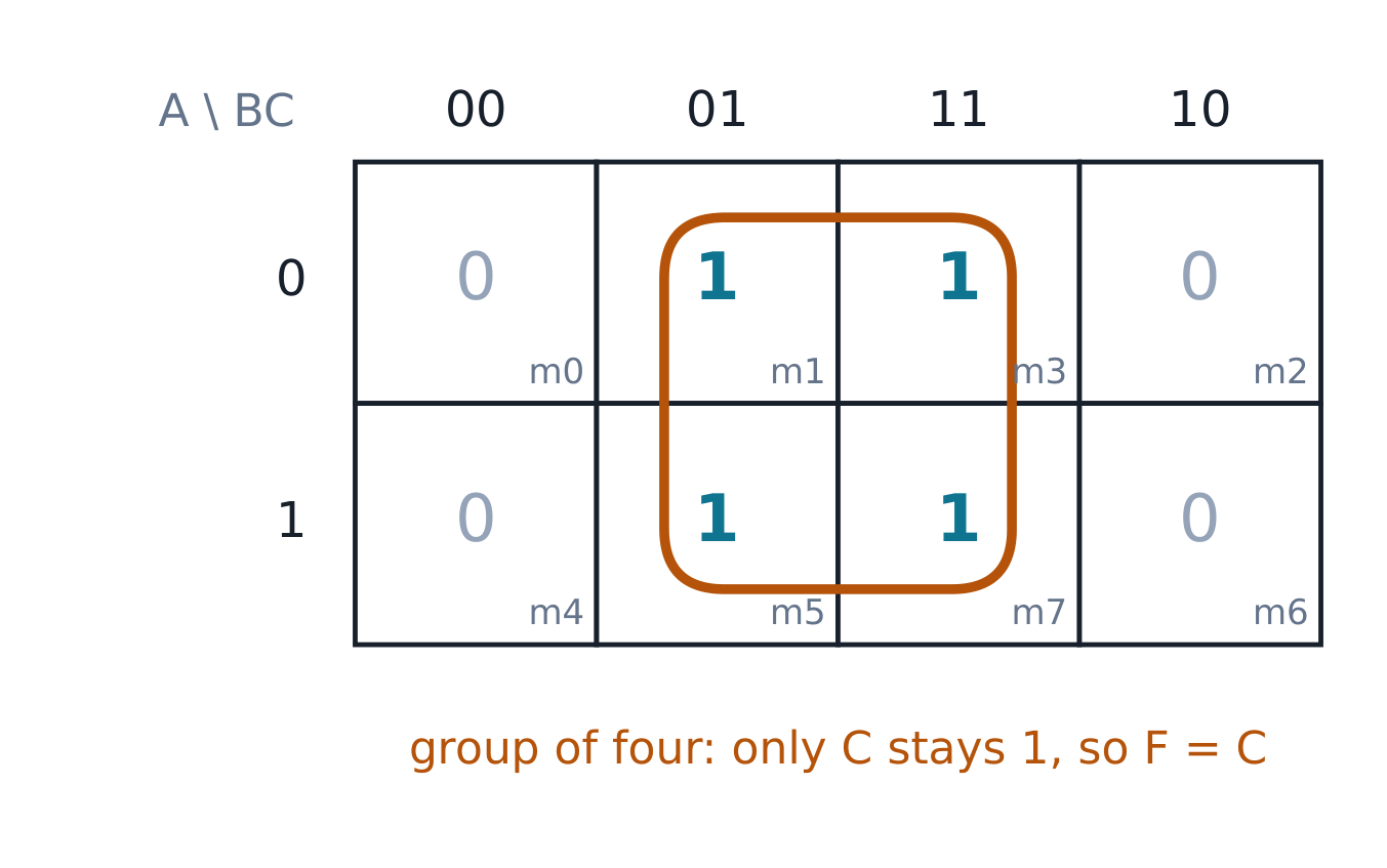
The Karnaugh map 卡诺图 arranges a truth table so adjacent cells differ in one variable (Gray-code order); groups of 1, 2, 4, 8 cells (powers of two, rectangles) read off as product terms.

Three-variable Karnaugh map with 1s in m1, m3, m5 and m7, the middle two columns, circled as one group of four
F = Σm(1, 3, 5, 7): the group of four keeps only C, so F = C

Worked example 1 (the odd function). The 3-variable function $F = \sum m(1, 3, 5, 7)$ (the odd rows) maps to a column pair — every cell where $C = 1$ — so $F = C$ directly: all four minterms share only $C$. The check: evaluate $C$ against all 8 rows of the original; it matches exactly (machine-verified). Don't-cares 无关项 (impossible input combinations) may join any group — use them to enlarge groups, never to create new ones.

Worked example 2 (the 4-variable majority, machine-verified, escalated). The majority function $M(A,B,C,D)$ is 1 when three or more inputs are 1: its minterms are $\sum m(7, 11, 13, 14, 15)$. Grouping on the 4-variable map: four overlapping groups of four give $M = A\cdot B\cdot(C + D) + C\cdot D\cdot(A + B)$. The machine check: evaluate both the definition (count $\geq 3$) and the expression on all 16 rows — they agree everywhere ✓. Notice the shape of the answer: majority is "any pair implies the rest" — the K-map found a factored form (4 AND-pairs and an OR of two products) rather than a flat 5-minterm sum, and the factored form is fewer gates.

Common mistakes. Grouping diagonals (cells must be rectangles in the Gray-code wrap-around, so edges touch). Writing a group term from variables that change inside the group — only the constant variables survive. Trusting an unverified simplification: the 16-row check is free.

Summary: Boolean laws plus De Morgan transform expressions; K-maps group power-of-two rectangles in Gray order; groups keep only constant variables; don't-cares enlarge but never create; verify every simplification exhaustively.

Vocabulary Train
English
boolean algebra/ˈbuːlɪən ˈældʒɪbrə/
absorption/əbˈsɔːpʃn/
de morgan's theorem/də ˈmɔːɡənz ˈθɪərəm/
karnaugh map/ˈkɑːnɔː mæp/
don't-cares
3.3

Combinational building blocks

A vending machine serves one of four drinks by two button presses: that selector, the decoder behind the display, the adder inside the change logic — combinational blocks are the reusable middle layer between gates and systems. Gates compose into standard combinational logic 组合逻辑 blocks whose behaviour is a pure function of the present inputs:

  • Multiplexer 多路选择器 (MUX): $2^n$-to-1 data selector; the n select bits choose one input. $Y = \sum (D_i \cdot minterm_i(selects))$.
  • Decoder 译码器: n inputs to $2^n$ outputs, exactly one high — the minterm generator.
  • Adder 加法器: a half adder 半加器 sums two bits ($S = A \oplus B$, carry $C = A\cdot B$); a full adder 全加器 adds three (two operands plus carry-in): $S = A \oplus B \oplus C_{in}$, $C_{out} = A\cdot B + C_{in}\cdot (A \oplus B)$.
Gate schematic of the full adder: two XOR gates for the sum, two AND gates and an OR for the carry, with inputs A, B, Cin wired through
The full adder: five gates, one of the most-reused circuits in computing

Worked example 1 (the MUX and the adder, checked). A 4-to-1 MUX with select $S_1S_0 = 10$ outputs $D_2$ — the decimal weight of the select code names the data input. The full-adder check at $A=1, B=1, C_{in}=1$: $S = 1\oplus 1\oplus 1 = 1$, $C_{out} = 1 + 1\cdot 0 = 1$ — three ones in, binary 11 out (sum 1, carry 1): $3 = 2 + 1$ ✓.

Worked example 2 (a 2-bit ripple adder, machine-verified, escalated). Chain two full adders: the first adds the low bits, its carry feeds the second. Adding $11_2 + 01_2$ ($3 + 1$): low bits $1 + 1$ give $S_0 = 0$, carry 1; high bits $1 + 0 + 1$ give $S_1 = 0$, carry 1 — output $100_2 = 4$ ✓ (machine checked through all four input pairs per stage). The pattern scales exactly: an n-bit adder is n full adders and nothing else, and the carry ripples through it — which is also its speed limit, fixed later by carry-lookahead.

Hazards 冒险 are momentary output glitches when input changes take unequal paths; they matter because a glitch can be caught as a clock edge. The remedy is redundant grouping (keeping the hazard cover) — detect them by enumeration when the specification forbids glitches.

Common mistakes. Reading a MUX backwards (the select chooses data, not the output's value). Forgetting the carry chain's direction in ripple adders. Treating a hazard as a logic error — the final value is right; the transient is the bug.

Summary: MUX selects by weighted code, decoder generates minterms, full adder = five gates summing three bits; ripple chains scale by repetition; hazards are transient, and redundant cover removes them.

Vocabulary Train
English
combinational logic/ˌkɒmbɪˈneɪʃənl ˈlɒdʒɪk/
multiplexer/ˈmʌltɪpleksə/
decoder/dɪˈkəʊdə/
adder/ˈædə/
half adder/hɑːf ˈædə/
full adder/fʊl ˈædə/
hazards
3.4

Latches and flip-flops

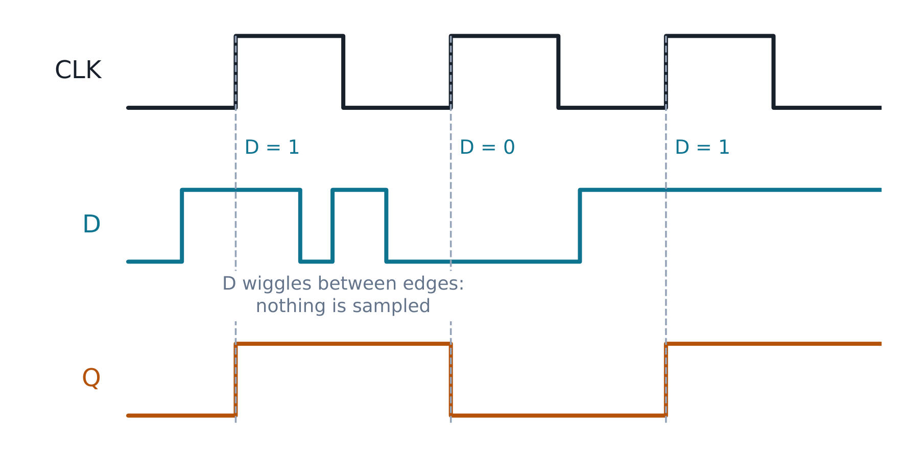
A doorbell remembers that it was pressed after the finger leaves — the simplest memory is feedback. Sequential logic 时序逻辑 has state — memory. A latch 锁存器 is level-sensitive: the SR latch (NOR cross-coupled) remembers which input pulsed; the D latch follows D while ENABLE is high, freezes when low. Flip-flops 触发器 are edge-triggered: the D flip-flop samples D at the clock edge 时钟边沿 and holds it until the next edge — Q after the edge equals D before it.

$$Q_{next} = D \quad \text{(D flip-flop, at each rising edge)}$$

The J-K flip-flop removes the SR forbidden state: $J=K=1$ toggles 翻转 ($Q'$ next). The excitation table 激励表 runs this backwards — given a desired transition $Q \to Q^+$, it lists the inputs required (D: $D = Q^+$; J-K: hold $0{,}0$, set $1{,}0$, reset $0{,}1$, toggle $1{,}1$).

Timing diagram: CLK, a D input that wiggles between edges, and Q changing only at rising edges to 1, 0, 1
Q copies D only at the rising clock edges

Worked example 1 (read the timing diagram). A D flip-flop sees $D = 1$ at the first rising edge, $D = 0$ at the second, $D = 1$ at the third: Q reads 1, 0, 1. Between edges, D may wiggle freely — nothing is sampled. Timing diagrams make this visible: Q changes only at edge instants.

Worked example 2 (the J-K sequence, machine-traced, escalated). Starting from Q = 0, apply $J,K$ = (1,0), (1,1), (0,1), (0,0). Step by step: (1,0) sets → 1; (1,1) toggles → 0; (0,1) resets → 0; (0,0) holds → 0. Q reads 1, 0, 0, 0 (machine-traced ✓). The design use: excitation tables run this backwards — to build a counter that goes 0 → 1 → 0 → 0 → 0, read each transition off the J-K table and the required inputs fall out (set, toggle, reset, hold). Flip-flop choice is a lookup, not a puzzle.

Common mistakes. Sampling on the wrong edge (falling vs rising — the specification says which). Confusing latch and flip-flop: a latch is transparent for a whole level, a flip-flop only at an instant. Expecting Q to change the moment D does — Q waits for the edge.

Summary: latches are level-transparent, flip-flops edge-triggered; Q after the edge = D before it; J-K removes the forbidden state with toggle; excitation tables invert behaviour into required inputs.

Vocabulary Train
English
sequential logic/siːˈkwenʃl ˈlɒdʒɪk/
latch/lætʃ/
flip-flops
at the clock edge
toggles
excitation table/eksɪˈteɪʃn ˈteɪbl/
3.5

Finite state machines

A vending machine rejects a coin sequence it accepted yesterday — not because the coins changed, but because the sequence differs. Sequences need a machine with memory of where it is: a finite state machine 有限状态机 (FSM) is states + transitions: a state diagram 状态图 (bubbles and labelled arrows), realised as next-state logic + state registers + output logic. Moore machines 穆尔机 compute outputs from state only (outputs change after the clock); Mealy machines 米利机 compute from state and inputs (outputs can change mid-cycle, sooner but glitch-prone).

State diagram of the parity detector: two bubbles EVEN and ODD; input-1 arrows cross between them, input-0 arrows loop back; the ODD bubble's output badge reads 1
Two states, one output: the parity detector's whole design

Worked example 1 (the parity detector, traced). Raise an output when the number of 1s seen is odd. Two states (EVEN, ODD); each input bit moves between them; output = (state == ODD). Sequence 1, 0, 1, 1: EVEN → ODD → ODD → EVEN → ODD, so the output after the fourth bit is 1 (three 1s seen — odd ✓ machine-traced). Design procedure: state diagram → state table → (binary) state encoding → excitation table for each flip-flop → minimise next-state logic. With one state bit ($0$ = EVEN, $1$ = ODD) the next-state logic is a single XOR: $Q^+ = Q \oplus in$ — the machine is a parity bit.

Worked example 2 (the 1011 detector, escalated). Detect the serial sequence 1011 (overlapping). States track the longest matched prefix: S0 (start), S1 (seen 1), S10 (seen 10), S101 (seen 101). Each transition goes to the longest tail of the input so far that is still a prefix of 1011:

State input 0 input 1
S0 S0 S1
S1 S10 S1
S10 S0 S101
S101 S10 S1, detect

From S101 a 1 completes 1011: the output says detected and the machine goes to S1, because the trailing "1" already starts the next match (the overlap). A 0 from S101 leaves "1010", whose tail "10" is a prefix, so it goes to S10, not back to S0. Four states need two flip-flops ($2^2 = 4$ ✓). Trace the stream 1,0,1,1,0,1,1: S0→S1→S10→S101→detect (S1), then 0→S10, 1→S101, 1→detect again. The stream holds two overlapping copies, at bits 1–4 and 4–7, and the machine finds both (machine-traced ✓). A detector that restarts at S0 after a match would miss the second. State minimisation merges equivalent states (same outputs, same next states) — an FSM with redundant states works but wastes flip-flops and logic.

Common mistakes. Forgetting the overlap reset (a matched suffix is the next match's prefix). Encoding states before checking the state table for equivalent states. Choosing Moore when the spec needs same-cycle response (Mealy), or Mealy when outputs feed asynchronous logic (glitches).

Summary: states + transitions + outputs; Moore from state, Mealy from state and input; diagram → table → encoding → excitation → minimise; overlap detection and state merging are where marks are won and lost.

Vocabulary Train
English
finite state machine/ˈfaɪnaɪt steɪt məˈʃiːn/
state diagram/steɪt ˈdaɪəɡræm/
3.6

Registers, counters and memory

A scoreboard shows 7, then 8 — one number changed while the rest stood still: that selective update is a register, and counting is a register that updates itself. A register 寄存器 is a bank of flip-flops sharing a clock: load n bits per edge. A shift register 移位寄存器 passes bits along: serial-in serial-out delays a bit stream; serial-in parallel-out converts serial to parallel.

A ripple counter 异步计数器 chains T-flip-flops (each output clocks the next); a synchronous counter 同步计数器 drives all clocks from one edge and computes each toggle with logic — no cumulative delay.

Register block diagram: 4 D flip-flops sharing CLK, with the counter's toggle logic feeding each D input; below, the timing trace 000→001→010→011
One clock, computed toggles: the synchronous counter's register and trace

Worked example 1 (the 3-bit up-counter, traced). A 3-bit synchronous up-counter toggles bit 0 every clock, bit 1 when $Q_0 = 1$, bit 2 when $Q_1\cdot Q_0 = 11$: after RESET, the counts run 000, 001, 010, 011 … 111, then roll to 000 (8 states = $2^3$ ✓ — the count range check; machine-traced). The toggle conditions are exactly the AND of all lower bits — a binary counter carries when every lower bit is 1, which is what "add 1" means.

Worked example 2 (a mod-6 counter, escalated). A mod-6 counter counts 000–101 and returns to 000 — six states, not eight. Detect the unused states: 110 is the first illegal code, so the reset condition is the AND of the two high bits ($Q_2\cdot Q_1$, with 111 also covered by it); wire that AND through clear logic (or as next-state logic = 000). Trace: 000, 001, 010, 011, 100, 101, then 110 never occurs — the machine jumps 101→000 ✓. Memory 存储器 is an organised array: k address bits select one of $2^k$ words of m bits — an 8K×8 memory has 13 address lines and 8 data lines ($8K = 2^{13} = 8192$ words ✓).

Common mistakes. Ripple counters look fine at low speed and fail at spec — the cumulative delay is per stage. Forgetting to handle the unused states in mod-N counters (they must recover to a legal state). Confusing shift direction conventions (MSB-first vs LSB-first serial).

Summary: registers load per shared edge; shift registers convert between serial and parallel; synchronous counters compute toggles with logic; mod-N needs unused-state handling; memory is $2^k$ words of m bits, k address lines.

Vocabulary Train
English
register/ˈredʒɪstə/
shift register/ʃɪft ˈredʒɪstə/
ripple counter/ˈrɪpl ˈkaʊntə/
synchronous counter/ˈsɪŋkrənəs ˈkaʊntə/
memory/ˈmeməri/
3.7

HDL and verification basics

Wiring 64 gates by hand invites 64 mistakes — and the industry's answer is not more careful drawing but description plus verification. A hardware description language 硬件描述语言 (Verilog/VHDL) describes structure and behaviour as synthesizable 可综合 code — what can become gates — separated from the testbench 测试平台, which simulates but never becomes hardware.

module full_adder(input a, b, cin, output sum, cout);
  assign sum  = a ^ b ^ cin;
  assign cout = (a & b) | (cin & (a ^ b));
endmodule
The Verilog module on the left and its simulated waveform on the right: the testbench drives all eight input combinations while sum and cout track a+b+cin
One module, one exhaustive testbench: description and proof together

Worked example 1 (the exhaustive testbench). The testbench drives all 8 input combinations and compares against the arithmetic truth ($a + b + cin = 2\cdot cout + sum$) — machine-verified: all 8 pass ✓. The property is the point: the reference model is arithmetic, not another gate description, so the check is independent of the implementation.

Worked example 2 (a shift register in HDL, escalated). Describe a 4-bit serial-in shift register:

module shift4(input clk, sin, output reg [3:0] q);
  always @(posedge clk) q <= {q[2:0], sin};
endmodule

The concatenation {q[2:0], sin} is the shift — in goes at the right, out falls off the left. The testbench drives sin = 1,0,1,1 over four clocks and the trace reads q = 0001, 0010, 0101, 1011 ✓ (machine-simulated) — unit 3.6's shift register, now a four-line description.

Common mistakes. Testbenches that restate the implementation (a copy proves nothing). Non-synthesizable constructs in hardware modules. Missing resets in always blocks — unit 3.6's trap again.

Summary: synthesizable module vs non-synthesizable testbench, always separate; the reference model must be independent (arithmetic or trace); exhaustive checks for small input spaces; ship modules with their proof.

Vocabulary Train
English
hardware description language/ˈhɑːdweə dɪˈskrɪpʃn ˈlæŋɡwɪdʒ/
synthesizable/ˈsɪnθəsaɪzəbl/
testbench/ˈtestbentʃ/
moore machines
mealy machines

Interactive lessons on this topic

Work through it step by step, with instant-check exercises.

More topics in University Electrical Engineering

Log in or create account

IGCSE, A-Level & AP