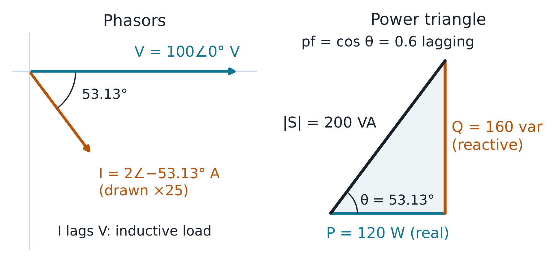
The 30 Ω resistor and +j40 Ω inductor give 50∠53.13° Ω in series, so a 100 V peak supply produces a 2 A peak current that lags by 53.13°. Compare the parallel example and a capacitive reactance, then connect each phasor to its instantaneous waveform.
At 100 V RMS, the 30 + j40 Ω load draws 2 A and uses 120 W plus 160 var. Compare no capacitor, exact correction and over-correction: supply current reaches a minimum at unity power factor, while load current and real power stay unchanged.
Summary: $\omega_{0} = 1/\sqrt{LC}$, $\alpha = R/2L$, three regimes by one
comparison; $\omega_{d}$ is the visible ringing; the slow root owns the tail;
แหล่งพลังงานสองแหล่ง → ค่าคงที่สองค่า → ตรวจสอบจุดปลายสองจุด
สำรวจ
One circuit, three damping regimes
$LC\ddot v_C+RC\dot v_C+v_C=0$
Release the 0.2 H and 0.05 F circuit from 1 V with zero current. Compare R = 2, 4 and 8 Ω on the same physical time axis, inspect the roots and energy, then change either initial condition to see why a second-order circuit needs both.
A radio's tuning circuit picks one station out of a crowded band by making one
ความถี่เป็นพิเศษ: ที่ ความถี่เรโซแนนซ์ ส่วนจินตภาพจะหักล้างกัน,
$\omega_{0}L = 1/(\omega_{0}C)$, นั่นคือ $\omega_{0} = 1/\sqrt{LC}$. มี
$Z = R$ (ต้านทานล้วนๆ, ต่ำสุด) กระแสไฟฟ้าจะมีค่าสูงสุด และมี
ความกว้างของแถบสัญญาณ$BW = R/L = \omega_{0}/Q$. ส่วนครึ่งของอิมพิแดนซ์หักล้างกัน
แม้ว่าแต่ละส่วนอาจมีค่าสูง — $V_{L}$ และ $V_{C}$ อาจเกินกว่า
แรงดันแหล่งจ่ายด้วยตัวคูณ Q.
|Z| ลดลงเหลือ R ที่ ω₀; จุดกำลังครึ่งอยู่ที่ที่ |Z| = √2·R
ตัวอย่างคำนวณ 1 (การขยายแรงดัน, ตรวจสอบแล้ว).$R = 5\ \Omega$,
$L = 0.1$ H, $C = 10\ \mu F$: $\omega_{0} = 1/\sqrt{0.1 \times 10^{-5}} =
1000$ rad/s; $Q = \omega_{0}L/R = 1000 \times 0.1/5 = 20$. At a source of
10 V, the current at resonance is $10/5 = 2$ A, and $V_{L} = \omega_{0}LI =
200$ V — twenty times the source. Check: $V_{C} = I/(\omega_{0}C) =
2/0.01 = 200$ V ✓; ทั้งสองมีค่า 200 V, แตกกัน 180° ผลรวมเป็นศูนย์
ตัวอย่างคำนวณ 2 (แถบกำลังครึ่ง, ขยายรายละเอียด). วงจรเดียวกันนี้
ความกว้างของแถบ: $BW = \omega_{0}/Q = 1000/20 = 50$ rad/s, และความถี่
กำลังครึ่งคำนวณได้ $\omega_{1} = 975.3$, $\omega_{2} = 1025.3$ rad/s —
their difference is 50.0 ✓ (machine-verified). They sit almost evenly either
side of 1000; exactly, $\omega_{1}\omega_{2} = \omega_{0}^{2}$ (symmetric on a
สถานีเพื่อนบ้านห่างออกไปสองช่วงความถี่กระแสไฟฟ้าลดลงเหลือ
ที่ขอบเขตแถบ $|Z| = \sqrt{2}R = 7.07\ \Omega$, กระแสมีค่า
$1/\sqrt{2}$ เท่าของค่าสูงสุด, และแต่ละองค์ประกอบรีแอกทีฟมีค่า
$Q/\sqrt{2} \approx 14$ เท่าของแรงดันแหล่งจ่าย — ยังเป็นการขยาย แต่ผ่าน
จุดสูงสุดไปแล้ว นี่คือคุณสมบัติการเลือก freq ที่เครื่องรับขาย: ที่ 900 rad/s (ซึ่ง
neighbouring station two bandwidths away) the current is down to
$10/\sqrt{R^{2} + (\omega L - 1/\omega C)^{2}} = 10/|5 + j(90 - 111.1)| =
10/21.7 = 0.46$ A — under a quarter of the resonant 2 A.
Common mistakes. Reporting $Q$-amplification without checking the other
element (both must match). Using $f_{0}$ where $\omega_{0}$ belongs (factor
$2\pi$). Believing resonance maximises power at any source impedance — it
ลดค่า |Z| ลงให้มากที่สุด ซึ่งเพิ่มกระแสได้สูงสุดเฉพาะเมื่อแหล่งจ่ายมีความแข็ง
A 10 V peak source drives the 5 Ω, 0.1 H and 10 µF circuit. At 1000 rad/s the current is 2 A and both reactive voltages are 200 V. Compare the half-power frequencies and the neighbouring 900 rad/s signal, then change resistance to connect Q with bandwidth.
การเพิ่มเสียงเบสคือฟิลเตอร์: แบนด์หนึ่งถูกยกขึ้น ส่วนที่เหลือไม่เปลี่ยนแปลง A filter
ส่งผ่านแบนด์หนึ่งและลดทอนส่วนที่เหลือ; ฟังก์ชันการถ่ายโอน $H(j\omega)$ มี
ตัวอย่างคำนวณ $20\log_{10}|H|$ (low-pass, ตรวจสอบจุดปลาย). Low-pass RC ที่มี
against log frequency: each pole contributes −20 dB/decade above its corner
frequency$\omega_{c} = 1/(RC)$; each zero +20 dB/decade.
สรุป: poles −20 dB/decade เหนือมุมตัด, zeros +20; −3 dB และ ±45° ที่
จุดตัด; เส้นประเป็นการออกแบบ, เส้นโค้งที่แท้จริงเป็นการตรวจสอบ.
สำรวจ
The exact curve rounds the Bode corner
$H_{total}=H_{stage}^{N}$
The 1.6 kΩ and 0.1 µF section has a 6250 rad/s corner. Compare exact gain and phase with straight-line approximations, swap the output to make a high-pass, and see how two buffered stages multiply gain and shift the overall half-power corner.
Shunt Y = −j0.1 S followed by series Z = j10 Ω gives A = 1 and D = 2. Reverse the blocks and those entries swap. Compare the z parameters and open-circuit input impedance, then connect a load and follow the opposite signs of I₂ and load current.