Skip to content · ⁨ข้ามไปยังเนื้อหา⁩

Electric Circuits · ⁨วงจรไฟฟ้า⁩

AP Physics C: Electricity and Magnetism · Topic 11 · ⁨หัวข้อ 11⁩

Video lesson for this topic · ⁨บทเรียนวิดีโอสำหรับหัวข้อนี้⁩ Open the video page · ⁨เปิดหน้าวิดีโอ⁩
8:44

วงจรไฟฟ้า

คุณสวิตช์ไฟ โคมไฟสว่างทันที อิเล็กตรอนต้องวิ่งตามสาย对吧? ไม่ hẳnเลย ภายในสายทองแดงนั้น ตัวพาประจุเคลื่อนที่ช้าๆ...

English narration · English + 中文 subtitles burned in · ⁨การบรรยายภาษาอังกฤษ · คำบรรยายภาษาอังกฤษ + 中文 ลอยตัวบนภาพ⁩

11.1

Electric Current · ⁨กระแสไฟฟ้า⁩

Syllabus · ⁨หลักสูตร⁩
English

Learning Objective 11.1.A: Describe the movement of electric charges through a medium.

  • 11.1.A.1 Current is the rate at which charge passes through a cross-sectional area of a wire.
    • Equation: $I = \dfrac{dq}{dt}$
    • 11.1.A.1.i Current within a conductor consists of charge carriers traveling through the conductor with an average drift velocity.
      • Equation: $I = nqv_d A$
    • 11.1.A.1.ii Electric charge moves in a circuit in response to an electric potential difference, sometimes referred to as electromotive force, or $\mathrm{emf}$ ($\mathcal{E}$).
    • 11.1.A.1.iii If the current is zero in a section of wire, the net motion of charge carriers in the wire is also zero, although individual charge carriers will not have zero speed.
  • 11.1.A.2 Current density is the flow of charge per unit area.
    • Equation: $I = \int \vec{J} \cdot d\vec{A}$
    • 11.1.A.2.i Current density is related to the motion of the charge carriers within a conductor.
      • Equation: $\vec{J} = nq\vec{v}_d$
    • 11.1.A.2.ii Current density is a vector quantity.
    • 11.1.A.2.iii A potential difference across a conductor creates an electric field within the conductor that is proportional to the resistivity of the conductor and the current density.
      • Equation: $\vec{E} = \rho\vec{J}$
  • 11.1.A.3 If a function of current density is given, the total current can be determined by integrating the current density over the area.
    • Equation: $I_{\text{tot}} = \int \vec{J}(r) \cdot d\vec{A}$
  • 11.1.A.4 Although current is a scalar quantity, it does have a direction. Because its direction is relative to the current carrier and not space, current does not obey the laws of vector addition and has no vector components.
    • 11.1.A.4.i The direction of conventional current is chosen to be the direction in which positive charge would move.
    • 11.1.A.4.ii In common circuits, the current is actually due to the movement of electrons (negative charge carriers).
ไทย

จุดประสงค์การเรียนรู้ 11.1.A: อธิบายการเคลื่อนที่ของประจุไฟฟ้าผ่านตัวกลาง

  • 11.1.A.1 กระแสไฟฟ้าคืออัตราการไหลของประจุไฟฟ้าที่ผ่านพื้นที่หน้าตัดของสายไฟ
    • สมการ: $I = \dfrac{dq}{dt}$
    • 11.1.A.1.i กระแสไฟภายในตัวนำประกอบด้วยตัวพาประจุที่เคลื่อนที่ผ่านตัวนำด้วยความเร็วลอยตัวเฉลี่ย (drift velocity)
      • สมการ: $I = nqv_d A$
    • 11.1.A.1.ii ประจุไฟฟ้าเคลื่อนที่ในวงจรตามผลต่างศักย์ไฟฟ้า บางครั้งเรียกว่า แรงดันไฟฟ้า หรือ $\mathrm{emf}$ ($\mathcal{E}$)
    • 11.1.A.1.iii หากกระแสไฟฟ้าเป็นศูนย์ในส่วนใดส่วนของลวด การเคลื่อนที่สุทธิของตัวพาประจุในลวดก็เป็นศูนย์เช่นกัน although ตัวพาประจุแต่ละตัวจะมีскорไม่เท่ากับศูนย์
  • 11.1.A.2 ความหนาแน่นของกระแสคืออัตราการไหลของประจุต่อหน่วยพื้นที่
    • สมการ: $I = \int \vec{J} \cdot d\vec{A}$
    • 11.1.A.2.i ความหนาแน่นกระแสสัมพันธ์กับการเคลื่อนที่ของพาหะประจุภายในตัวนำ
      • สมการ: $\vec{J} = nq\vec{v}_d$
    • 11.1.A.2.ii ความหนาแน่นกระแสเป็นปริมาณเวกเตอร์
    • 11.1.A.2.iii ความต่างศักย์ระหว่างปลายตัวนำจะสร้างสนามไฟฟ้าภายในตัวนำซึ่งแปรผันตรงกับค่าความต้านทานจำเพาะของความต้านทานและความหนาแน่นกระแส
      • สมการ: $\vec{E} = \rho\vec{J}$
  • 11.1.A.3 หากกำหนดฟังก์ชันของความหนาแน่นกระแสไว้ สามารถหากระแสรวมได้โดยการอินทิเกรตความหนาแน่นกระแสบนพื้นที่
    • สมการ: $I_{\text{tot}} = \int \vec{J}(r) \cdot d\vec{A}$
  • 11.1.A.4 แม้กระแสจะเป็นปริมาณสเกลาร์ แต่ก็มีทิศทาง เนื่องจากทิศทางขึ้นอยู่กับตัวพากระแสไม่ใช่ตำแหน่งในอวกาศ กระแสจึงไม่ปฏิบัติตามกฎการบวกเวกเตอร์และไม่มีส่วนประกอบของเวกเตอร์
    • 11.1.A.4.i ทิศทางของกระแสแบบดั้งเดิมถูกกำหนดให้เป็นทิศทางที่ประจุบวกจะเคลื่อนที่
    • 11.1.A.4.ii ในวงจรทั่วไป กระแสไฟฟ้าเกิดจากการเคลื่อนที่ของอิเล็กตรอน (พาหะประจุลบ)
Source: College Board AP Course and Exam Description · ⁨แหล่งที่มา: คำอธิบายหลักสูตรและข้อสอบ College Board AP⁩

English

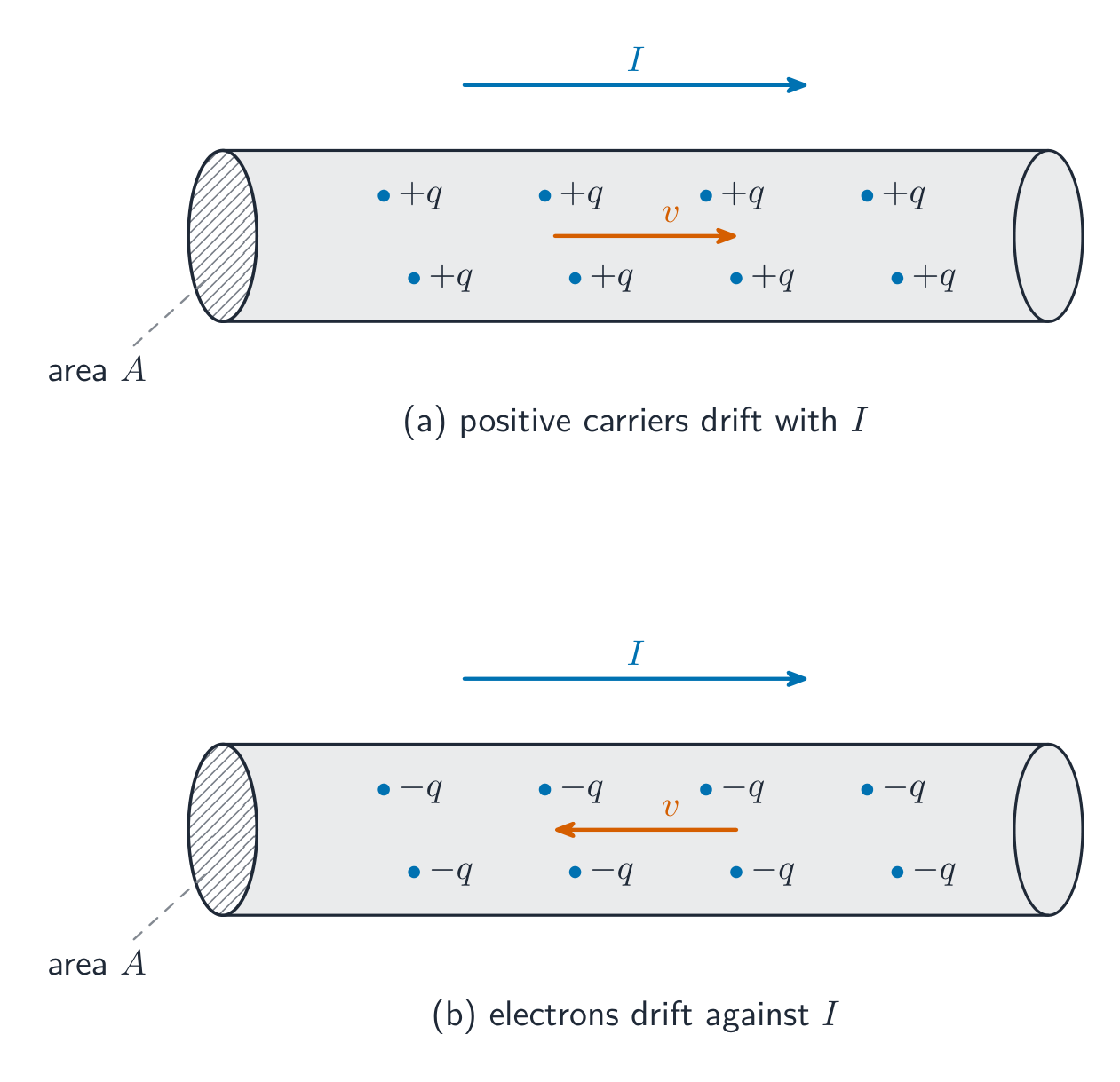
Electric current 电流 is the rate at which charge passes a cross-section of wire, $I=\dfrac{dq}{dt}$, measured in amperes 安培. Conventional current points the way positive charge would move. Microscopically, a current is a slow drift of many carriers:

$$I=nqv_dA,$$

with $n$ the number of carriers per volume, $q$ the charge each carries, $v_d$ the drift velocity 漂移速度, and $A$ the cross-sectional area 横截面积.

Worked example. A copper wire with $A=1.0\times10^{-6}\ \text{m}^2$ and $n=8.5\times10^{28}\ \text{m}^{-3}$ carries $1.7\ \text{A}$. Then $v_d=\dfrac{I}{nqA}=\dfrac{1.7}{(8.5\times10^{28})(1.6\times10^{-19})(1.0\times10^{-6})}\approx1.3\times10^{-4}\ \text{m/s}$ – the carriers drift slower than a snail, even though the signal travels near light speed.

Current density 电流密度 is charge flow per unit area, $\vec{J}=nq\vec{v}_d$, linked to the field driving it by $\vec{E}=\rho\vec{J}$. In general $I=\int\vec{J}\cdot d\vec{A}$; if $J(r)$ varies across the wire, integrate it over the cross-section to get the total current. One care point: current has a direction along its wire, but it is a scalar 标量 – currents do not add as vectors, and there are no "components of current".

ไทย

กระแสไฟฟ้า คืออัตราการไหลของประจุผ่านหน้าตัดของลวด, $I=\dfrac{dq}{dt}$, วัดในหน่วย แอมแปร์ กระแสปกติชี้ไปในทิศทางที่ ประจุบวก จะเคลื่อนที่ ในระดับจุลภาค กระแสคือการเคลื่อนที่ช้าๆ ของตัวพาจำนวนมาก:

$$I=nqv_dA,$$

โดยที่ $n$ คือจำนวนตัวพาต่อปริมาตร, $q$ เป็นประจุที่แต่ละตัวพาถือ, $v_d$ คือ ความเร็วลอยตัว, และ $A$ คือ พื้นที่หน้าตัด

ตัวพาประจุลอยตัวช้าๆ ผ่านตัวนำเพื่อสร้างกระแส

ตัวอย่างวิธีทำ ลวดทองแดงที่มี $A=1.0\times10^{-6}\ \text{m}^2$ และ $n=8.5\times10^{28}\ \text{m}^{-3}$ ไหลกระแส $1.7\ \text{A}$. แล้ว $v_d=\dfrac{I}{nqA}=\dfrac{1.7}{(8.5\times10^{28})(1.6\times10^{-19})(1.0\times10^{-6})}\approx1.3\times10^{-4}\ \text{m/s}$ – ตัวพาเคลื่อนที่ช้ากว่าเต่า แม้สัญญาณจะเดินทางด้วยความ接近แสงก็ตาม

ความหนาแน่นกระแส คือการไหลของประจุต่อหน่วยพื้นที่, $\vec{J}=nq\vec{v}_d$, เชื่อมโยงกับสนามที่ขับเคลื่อน它以 $\vec{E}=\rho\vec{J}$. โดยทั่วไป $I=\int\vec{J}\cdot d\vec{A}$; ถ้า $J(r)$ เปลี่ยนแปลงไปตามหน้าตัดลวด ให้อินทิกรัลมันเพื่อหากระแสรวม ข้อควรระวัง: กระแสมีทิศทางตามลวด但它เป็น สเกลาร์ – กระแสไม่รวมกันแบบเวกเตอร์ และไม่มี "องค์ประกอบของกระแส"

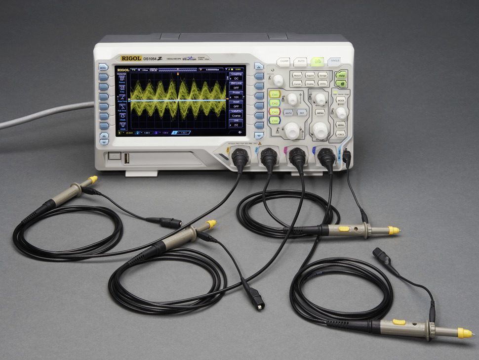
ออสซิลโลสโคป: แรงดันเทียบกับเวลาแสดงถึงวิวัฒนาการของกระแสและประจุในวงจร
ออสซิลโลสโคป: กราฟแรงดันไฟฟ้าเทียบกับเวลาแสดงการเปลี่ยนแปลงของกระแสและประจุในวงจร
Vocabulary · ⁨คำศัพท์⁩ Train · ⁨ฝึกฝน⁩
English ไทย
Electric current/ɪˈlektrɪk ˈkʌrənt/ กระแสไฟฟ้า
amperes/ˈæmpeəz/ แอมแปร์ (amperes)
drift velocity/drɪft vəˈlɒsɪti/ ความเร็วลอยตัว
cross-sectional area/krɒs ˈsekʃənl ˈeərɪə/ พื้นที่หน้าตัด
Current density/ˈkʌrənt ˈdensɪti/ ความหนาแน่นกระแส
scalar/ˈskeɪlə/ สเกลาร์
circuit diagram/ˈsɜːkɪt ˈdaɪəɡræm/ แผนวงจรไฟฟ้า
series/ˈsɪəriːz/ 串联电路中
11.2

Electric Circuits · ⁨วงจรไฟฟ้า⁩

Syllabus · ⁨หลักสูตร⁩
English

Learning Objective 11.2.A: Describe the behavior of a circuit.

  • 11.2.A.1 A circuit is composed of electrical loops, which can include wires, batteries, resistors, lightbulbs, capacitors, inductors, switches, ammeters, and voltmeters.
  • 11.2.A.2 A closed electrical loop is a closed path through which charges may flow.
    • 11.2.A.2.i A closed circuit is one in which charges would be able to flow.
    • 11.2.A.2.ii An open circuit is one in which charges would not be able to flow.
    • 11.2.A.2.iii A short circuit is one in which charges would be able to flow with no change in potential difference.
  • 11.2.A.3 A single circuit element may be part of multiple electrical loops.
  • 11.2.A.4 Circuit schematics are representations used to describe and analyze electric circuits.
    • 11.2.A.4.i The properties of an electric circuit are dependent on the physical arrangement of its constituent elements.
    • 11.2.A.4.ii Circuit elements have common symbols that are used to create schematic diagrams. Variable elements are indicated by a diagonal strikethrough arrow across the standard symbol for that element. (Symbols: Battery, Bulb, Switch, Capacitor, Resistor, Ammeter, Voltmeter, Inductor.)

Boundary statement: Unless otherwise specified, all circuit schematic diagrams will be drawn using conventional current.

ไทย

จุดประสงค์การเรียนรู้ 11.2.A: อธิบายพฤติกรรมของวงจรไฟฟ้า

  • 11.2.A.1 วงจรประกอบด้วยลูปไฟฟ้า ซึ่งอาจมีสายไฟ แบตเตอรี่ ตัวต้านทาน หลอดไฟ condensers Inductors สวิตช์ อมมิเตอร์ และโวลต์มิเตอร์
  • 11.2.A.2 วงจรรอบไฟฟ้าปิดคือเส้นทางปิดที่ประจุสามารถไหลผ่านได้
    • 11.2.A.2.i วงจรปิดคือวงจรที่ประจุจะสามารถไหลผ่านได้
    • 11.2.A.2.ii วงจรเปิดคือวงจรที่ประจุไม่สามารถไหลผ่านได้
    • 11.2.A.2.iii วงจรลัดคือวงจรที่ประจุจะสามารถไหลผ่านได้โดยไม่มีการเปลี่ยนแปลงของความต่างศักย์
  • 11.2.A.3 องค์ประกอบวงจรหนึ่งอาจเป็นส่วนหนึ่งของวงจรรอบไฟฟ้าหลายวง
  • 11.2.A.4 แผนภาพวงจรใช้เพื่ออธิบายและวิเคราะห์วงจรไฟฟ้า
    • 11.2.A.4.i คุณสมบัติของวงจรไฟฟ้าขึ้นอยู่กับการจัดวางทางกายภาพขององค์ประกอบต่างๆ ที่ประกอบกัน
    • 11.2.A.4.ii องค์ประกอบในวงจรมีสัญลักษณ์มาตรฐานที่ใช้ในการวาดแผนภาพวงจร องค์ประกอบที่ปรับค่าได้จะแสดงด้วยลูกศรขีดฆ่าเฉียงทับสัญลักษณ์มาตรฐานขององค์ประกอบนั้น (สัญลักษณ์: แบตเตอรี่, หลอดไฟ, สวิตช์, ตัวเก็บประจุ, ตัวต้านทาน, แอมมิเตอร์, โวลต์มิเตอร์, คอยล์เหนี่ยวนำ)

คำประกาศขอบเขต: เว้นแต่จะระบุไว้เป็นพิเศษ แผนภาพวงจรทั้งหมดจะถูกวาดโดยใช้กระแสไฟฟ้าแบบดั้งเดิม

Source: College Board AP Course and Exam Description · ⁨แหล่งที่มา: คำอธิบายหลักสูตรและข้อสอบ College Board AP⁩

English

A circuit is a set of closed loops built from wires, batteries, resistors, lightbulbs, capacitors, inductors, switches, and meters; charge can flow only around a closed path. One element can belong to several loops at once – that is what makes multi-loop problems interesting. Every analysis starts by reading the circuit diagram 电路图: trace each loop and identify which elements share the same current (series 串联) and which share the same potential difference (parallel 并联).

ไทย

วงจรคือชุดของวงปิดที่สร้างจากสายไฟ แบตเตอรี่ ตัวต้านทาน หลอดไฟ ตัวเก็บประจุ ตัวเหนี่ยวนำ สวิตช์ และมิเตอร์; ประจุสามารถไหลได้เฉพาะรอบเส้นทาง ปิด เท่านั้น องค์ประกอบหนึ่งอาจเป็นส่วนหนึ่งของหลายวงพร้อมกัน – นั่นคือสิ่งที่ทำให้ปัญหาหลายวงน่าสนใจ การวิเคราะห์ทุกแบบเริ่มต้นด้วยการอ่าน แผนภาพวงจร: ตามแต่ละวงและระบุว่าองค์ประกอบใดแบ่งกระแสเดียวกัน (อนุกรม) และองค์ประกอบใดแบ่งผลต่างศักย์เดียวกัน (ขนาน)

Explore · ⁨สำรวจ⁩

Build series and parallel circuits · ⁨สร้างวงจรแบบอนุกรมและขนาน⁩

In series the same current flows through every bulb and voltage divides; in parallel each branch gets the full voltage. Switch mode to see the bulbs' brightness change. · ⁨ใน แบบอนุกรม กระแสไฟเท่ากันไหลผ่านหลอดไฟทุกดวงและแรงดันไฟฟ้าแบ่งกัน; ใน แบบขนาน แต่ละสาขาได้รับแรงดันไฟฟ้าเต็ม สลับโหมดเพื่อดูความสว่างของหลอดไฟเปลี่ยนไป⁩

11.3

Resistance, Resistivity, and Ohm's Law · ⁨ความต้านทาน, ความต้านทานจำเพาะ, และกฎของโอห์ม⁩

Syllabus · ⁨หลักสูตร⁩
English

Learning Objective 11.3.A: Describe the resistance of an object using physical properties of that object.

  • 11.3.A.1 Resistance is a measure of the degree to which an object opposes the movement of electric charge.
  • 11.3.A.2 The resistance of a resistor with uniform geometry is proportional to its resistivity and length and is inversely proportional to its cross-sectional area.
    • Equation: $R = \dfrac{\rho\ell}{A}$
    • 11.3.A.2.i Resistivity is a fundamental property of a material that depends on its atomic and molecular structure and quantifies how strongly the material opposes the motion of electric charge.
    • 11.3.A.2.ii The resistivity of a conductor typically increases with temperature.
    • 11.3.A.2.iii The total resistance of a resistor with uniform geometry, but that is made of a material whose resistivity varies along the length of the resistor, is given by $R = \int \dfrac{\rho(\ell)\,d\ell}{A}$.

Learning Objective 11.3.B: Describe the electrical characteristics of elements of a circuit.

  • 11.3.B.1 Ohm's law relates current, resistance, and potential difference across a conductive element of a circuit.
    • Equation: $I = \dfrac{\Delta V}{R}$
    • 11.3.B.1.i Materials that obey Ohm's law have constant resistance for all currents and are called ohmic materials.
    • 11.3.B.1.ii The resistivity of an ohmic material is constant regardless of temperature.
    • 11.3.B.1.iii Resistors can also convert electrical energy to thermal energy, which may change the temperature of both the resistor and the resistor's environment.
    • 11.3.B.1.iv The resistance of an ohmic circuit element can be determined from the slope of a graph of the current in the element as a function of the potential difference across the element.
ไทย

จุดประสงค์การเรียนรู้ 11.3.A: อธิบายความต้านทานของวัตถุโดยใช้คุณสมบัติทางกายภาพของวัตถุนั้น

  • 11.3.A.1 ความต้านทานคือตัวบ่งชี้ถึงระดับที่วัตถุขัดขวางการเคลื่อนที่ของประจุไฟฟ้า
  • 11.3.A.2 ความต้านทานของตัวต้านทานที่มีรูปทรงสม่ำเสมอจะแปรผันตรงกับค่าความต้านทานจำเพาะและความยาวของมัน และแปรผกผันกับพื้นที่หน้าตัดของมัน
    • สมการ: $R = \dfrac{\rho\ell}{A}$
    • 11.3.A.2.i ความต้านทานจำเพาะเป็นคุณสมบัติพื้นฐานของวัสดุที่ขึ้นอยู่กับโครงสร้างอะตอมและโมเลกุลของวัสดุนั้น และวัดระดับที่วัสดุนั้นขัดขวางการเคลื่อนที่ของประจุไฟฟ้า
    • 11.3.A.2.ii ความต้านทานจำเพาะของตัวนำมักเพิ่มขึ้นเมื่ออุณหภูมิสูงขึ้น
    • 11.3.A.2.iii ความต้านทานรวมของตัวต้านทานที่มีเรขาคณิตสม่ำเสมอแต่ทำจากวัสดุwhoseความต้านทานจำเพาะแปรผันตามความยาวของตัวต้านทาน ให้โดย $R = \int \dfrac{\rho(\ell)\,d\ell}{A}$

จุดประสงค์การเรียนรู้ 11.3.B: อธิบายลักษณะทางไฟฟ้าขององค์ประกอบในวงจร

  • 11.3.B.1 กฎของโอห์มเชื่อมโยงความสัมพันธ์ระหว่างกระแสไฟฟ้า ความต้านทาน และความต่างศักย์ข้ามองค์ประกอบนำไฟฟ้าในวงจร
    • สมการ: $I = \dfrac{\Delta V}{R}$
    • 11.3.B.1.i วัสดุที่ปฏิบัติตามกฎของโอห์มมีความต้านทานคงที่สำหรับทุกกระแสและเรียกว่า วัสดุแบบโอห์มิก
    • 11.3.B.1.ii ความต้านทานจำเพาะของวัสดุแบบโอห์มิกจะคงที่ไม่ว่าอุณหภูมิจะเปลี่ยนแปลงหรือไม่
    • 11.3.B.1.iii ตัวต้านทานยังสามารถแปลงพลังงานไฟฟ้าเป็นพลังงานความร้อนได้ ซึ่งอาจทำให้ทั้งตัวต้านทานและสภาพแวดล้อมรอบตัวมันมีอุณหภูมิเปลี่ยนแปลงไป
    • 11.3.B.1.iv ความต้านทานขององค์ประกอบวงจรแบบโอห์มิกสามารถหาได้จากความชันของกราฟที่แสดงความสัมพันธ์ระหว่างกระแสในองค์ประกอบกับความต่างศักย์ข้ามองค์ประกอบนั้น

Source: College Board AP Course and Exam Description · ⁨แหล่งที่มา: คำอธิบายหลักสูตรและข้อสอบ College Board AP⁩

English

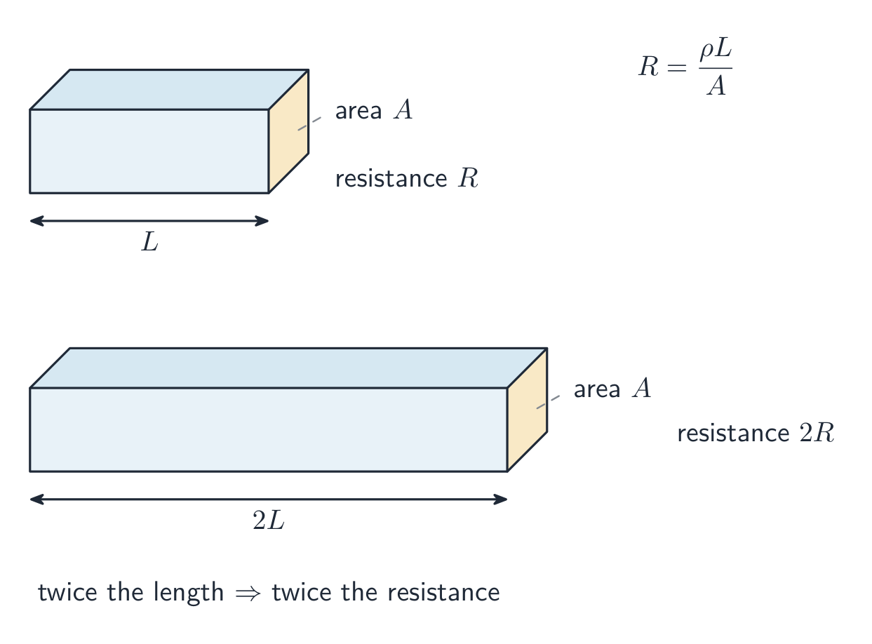
Resistance 电阻 measures how strongly an object opposes charge flow. It grows with the material's resistivity 电阻率 and the conductor's length, and shrinks with its area:

$$R=\frac{\rho\,\ell}{A}.$$

Ohm's law 欧姆定律 relates the current through an element to the potential difference across it:

$$I=\frac{\Delta V}{R}.$$

Worked example. Stretch a wire to double its length: the volume is fixed, so the area halves, and $R=\rho\ell/A$ becomes $\rho(2\ell)/(A/2)=4R$ – four times the resistance. An element is ohmic 欧姆性 if $R$ stays constant (a straight line through the origin on an $I$–$\Delta V$ graph); a lightbulb filament, which heats up, is not.

ไทย

ความต้านทาน บ่งบอกถึงความสามารถในการขัดขวางการไหลของประจุ มันเพิ่มขึ้นตาม ความต้านทานจำเพาะ ของวัสดุและความยาวของตัวนำ และลดลงตามพื้นที่หน้าตัด:

$$R=\frac{\rho\,\ell}{A}.$$

กฎของโอห์ม เชื่อมโยงกระแสที่ผ่านองค์ประกอบกับผลต่างศักย์ที่ตกคร่อมมัน:

$$I=\frac{\Delta V}{R}.$$
ตัวนำที่ยาวขึ้นมีความต้านทานมากกว่า; ตัวนำที่กว้างขึ้นมีความต้านทานน้อยกว่า

ตัวอย่างวิธีทำ. ดึงลวดให้ยาวเป็นสองเท่า: ปริมาตรคงที่ ดังนั้นพื้นที่หน้าตัดจะเหลือครึ่งหนึ่ง, และ $R=\rho\ell/A$ จะกลายเป็น $\rho(2\ell)/(A/2)=4R$ – ความต้านทานเพิ่มสี่เท่า องค์ประกอบที่เป็น โอห์มิก คือเมื่อ $R$ คงที่ (เส้นตรงผ่านจุดกำเนิดบนกราฟ $I$–$\Delta V$); เกลียวหลอดไฟซึ่งร้อนขึ้น就不是.

Explore · ⁨สำรวจ⁩

Apply Ohm's law · ⁨ใช้กฎของโอห์ม⁩

Ohm's law $V=IR$: for a fixed resistance, current is proportional to voltage. Raise the resistance and the same voltage pushes less current. · ⁨กฎของโอห์ม $V=IR$: สำหรับความต้านทานคงที่ กระแสไฟแปรผันตรงกับแรงดันไฟฟ้า เพิ่มความต้านทานแล้วแรงดันไฟฟ้าเท่าเดิมจะดันกระแสไฟได้น้อยลง⁩

Vocabulary · ⁨คำศัพท์⁩ Train · ⁨ฝึกฝน⁩
English ไทย
resistivity/ˌriːzɪˈstɪvəti/ ความต้านทานจำเพาะ
Ohm's law/əʊmz lɔː/ กฎของโอห์ม
ohmic/ˈəʊmɪk/ ohmic ohmic
equivalent resistance/ɪˈkwɪvələnt rɪˈzɪstəns/ ความต้านทานเทียบเท่า
ideal battery/aɪˈdɪəl ˈbætəri/ แบตเตอรี่ในอุดมคติ
internal resistance/ɪnˈtɜːnl rɪˈzɪstəns/ ความต้านทานภายใน
terminal voltage/ˈtɜːmɪnl ˈvəʊltɪdʒ/ แรงดันขั้ว
ammeter/ˈæmiːtə/ แอมมิเตอร์
voltmeter/ˈvəʊltmiːtə/ โวลต์มิเตอร์
Kirchhoff's loop rule/ˈkɜːkhɒfs luːp ruːl/ กฎวงจรของเคิร์ชโฮฟฟ์
Kirchhoff's junction rule/ˈkɜːkhɒfs ˈdʒʌŋkʃn ruːl/ กฎโหนดของเคิร์ชโฮฟฟ์
junction/ˈdʒʌŋkʃn/ จุดแยก
equivalent capacitance/ɪˈkwɪvələnt kəˈpæsɪtəns/ ความจุเทียบเท่า
RC circuit/ˌɑː ˈsiː ˈsɜːkɪt/ วงจร RC
11.4

Electric Power · ⁨กำลังไฟฟ้า⁩

Syllabus · ⁨หลักสูตร⁩
English

Learning Objective 11.4.A: Describe the transfer of energy into, out of, or within an electric circuit, in terms of power.

  • 11.4.A.1 The rate at which energy is transferred, converted, or dissipated by a circuit element depends on the current in the element and the electric potential difference across it.
    • Equation: $P = I\Delta V$
    • Equation: $P = I^2 R = \dfrac{\Delta V^2}{R}$
  • 11.4.A.2 The brightness of a lightbulb increases with power, so power can be used to qualitatively predict the brightness of lightbulbs in a circuit.

Boundary statement: AP Physics C: Electricity & Magnetism only expects students to analyze the transfer of mechanical and electrical energy, although students should be aware that electrical energy can also be dissipated in the form of thermal energy.

ไทย

จุดประสงค์การเรียนรู้ 11.4.A: อธิบายการถ่ายโอนพลังงานเข้าสู่ ออก หรือภายในวงจรไฟฟ้า โดยใช้หน่วยกำลังไฟฟ้า

  • 11.4.A.1 อัตราที่พลังงานถูกถ่ายโอน แปลงสภาพ หรือสูญเสียโดยองค์ประกอบวงจรขึ้นอยู่กับกระแสไฟฟ้าในองค์ประกอบและความต่างศักย์ไฟฟ้าข้ามองค์ประกอบนั้น
    • สมการ: $P = I\Delta V$
    • สมการ: $P = I^2 R = \dfrac{\Delta V^2}{R}$
  • 11.4.A.2 ความสว่างของหลอดไฟเพิ่มขึ้นตามกำลังไฟฟ้า ดังนั้นกำลังไฟฟ้าจึงสามารถใช้ทำนายความสว่างของหลอดไฟในวงจรได้อย่างเชิงคุณภาพ

คำชี้ขอบเขต: AP Physics C: ไฟฟ้าและแม่เหล็ก จะเน้นให้ผู้เรียนวิเคราะห์การถ่ายโอนพลังงานกลและไฟฟ้าเท่านั้น แม้ว่าผู้เรียนควรทราบว่าพลังงานไฟฟ้าสามารถสูญเสียไป的形式เป็นพลังงานความร้อนได้เช่นกัน

Source: College Board AP Course and Exam Description · ⁨แหล่งที่มา: คำอธิบายหลักสูตรและข้อสอบ College Board AP⁩

English

A charge $q$ falling through a potential difference $\Delta V$ gives up energy $q\Delta V$, so the rate of energy transfer in an element is

$$P=I\,\Delta V=I^2R=\frac{(\Delta V)^2}{R}.$$

In a resistor all of it becomes heat. Use the form whose quantities you actually know – and use power to rank lightbulb brightness: brighter = more power, not necessarily more resistance. In series, the larger resistance is brighter ($P=I^2R$, same $I$); in parallel, the smaller one is ($P=\Delta V^2/R$, same $\Delta V$).

ไทย

ประจุ $q$ ที่ตกลงผ่านผลต่างศักย์ $\Delta V$ จะปล่อยพลังงาน $q\Delta V$, ดังนั้นอัตราการถ่ายโอนพลังงานในองค์ประกอบคือ

$$P=I\,\Delta V=I^2R=\frac{(\Delta V)^2}{R}.$$

ในตัวต้านทานทั้งหมดจะเปลี่ยนเป็นความร้อน ใช้รูปแบบที่มีปริมาณที่คุณรู้จริง – และใช้กำลังไฟเพื่อจัดอันดับความสว่างของหลอดไฟ: สว่างกว่า = กำลังไฟมากกว่า ไม่ใช่ความต้านทานมากกว่าเสมอไป ในอนุกรม, ตัวต้านทานที่ ใหญ่กว่า จะสว่างกว่า ($P=I^2R$, กระแส $I$ เดียวกัน); ในขนาน, ตัวที่ เล็กกว่า จะสว่างกว่า ($P=\Delta V^2/R$, ผลต่างศักย์ $\Delta V$ เดียวกัน).

Explore · ⁨สำรวจ⁩

Read an I-V characteristic · ⁨อ่านกราฟลักษณะ I-V⁩

Power is $P=IV$. A resistor's I-V line is straight, but a lamp curves as it heats and its resistance rises. The area under I-V relates to the energy delivered. · ⁨กำลังคือ $P=IV$. กราฟ I-V ของตัวต้านทานเป็นเส้นตรง แต่ โคมไฟ มีเส้นโค้งเมื่อร้อนขึ้นและความต้านทานเพิ่มขึ้น พื้นที่ใต้กราฟ I-Vสัมพันธ์กับพลังงานที่ส่งมอบ⁩

11.5

Compound Direct Current Circuits · ⁨วงจรกระแสตรงแบบผสม⁩

Syllabus · ⁨หลักสูตร⁩
English

Learning Objective 11.5.A: Describe the equivalent resistance of multiple resistors connected in a circuit.

  • 11.5.A.1 Circuit elements may be connected in series and/or in parallel.
    • 11.5.A.1.i A series connection is one in which any charge passing through one circuit element must proceed through all elements in that connection and has no other path available. The current in each element in series must be the same.
    • 11.5.A.1.ii A parallel connection is one in which charges may pass through one of two or more paths. Across each path, the potential difference is the same.
  • 11.5.A.2 A collection of resistors in a circuit may be analyzed as though it were a single resistor with an equivalent resistance $R_{\text{eq}}$.
    • 11.5.A.2.i The equivalent resistance of a set of resistors in series is the sum of the individual resistances.
      • Equation: $R_{\text{eq},s} = \sum_{i} R_i$
    • 11.5.A.2.ii The inverse of the equivalent resistance of a set of resistors connected in parallel is equal to the sum of the inverses of the individual resistances.
      • Equation: $\dfrac{1}{R_{\text{eq},p}} = \sum_{i} \dfrac{1}{R_i}$
    • 11.5.A.2.iii When resistors are connected in parallel, the number of paths available to charges increases, and the equivalent resistance of the group of resistors decreases.

Learning Objective 11.5.B: Describe a circuit with resistive wires and a battery with internal resistance.

  • 11.5.B.1 Ideal batteries have negligible internal resistance. Ideal wires have negligible resistance.
    • 11.5.B.1.i The resistance of wires that are good conductors may normally be neglected, because their resistance is much smaller than that of other elements of a circuit.
    • 11.5.B.1.ii The resistance of wires may only be neglected if the circuit contains other elements that do have resistance.
    • 11.5.B.1.iii The potential difference a battery would supply if it were ideal is the potential difference measured across the terminals when there is no current in the battery and is sometimes referred to as its $\mathrm{emf}$ ($\mathcal{E}$).
  • 11.5.B.2 The internal resistance of a nonideal battery may be treated as the resistance of a resistor in series with an ideal battery and the remainder of the circuit.
  • 11.5.B.3 When there is current in a nonideal battery with internal resistance $r$, the potential difference across the terminals of the battery is reduced relative to the potential difference when there is no current in the battery.
    • Equation: $\Delta V_{\text{terminal}} = \mathcal{E} - Ir$

Learning Objective 11.5.C: Describe the measurement of current and potential difference in a circuit.

  • 11.5.C.1 Ammeters are used to measure current at a specific point in a circuit.
    • 11.5.C.1.i Ammeters must be connected in series with the element in which current is being measured.
    • 11.5.C.1.ii Ideal ammeters have zero resistance so that they do not affect the current in the element that they are in series with.
  • 11.5.C.2 Voltmeters are used to measure electric potential difference between two points in a circuit.
    • 11.5.C.2.i Voltmeters must be connected in parallel with the element across which potential difference is being measured.
    • 11.5.C.2.ii Ideal voltmeters have infinite resistance so that no charge flows through them.
  • 11.5.C.3 Nonideal ammeters and voltmeters will change the properties of the circuit being measured.

Boundary statement: Unless otherwise stated, all batteries, wires, and meters are assumed to be ideal. Circuits with batteries of different potential differences connected in parallel will not be assessed.

ไทย

จุดประสงค์การเรียนรู้ 11.5.A: อธิบายความต้านทานเทียบเท่าของตัวต้านทานหลายตัวที่ต่ออยู่ในวงจร

  • 11.5.A.1 องค์ประกอบวงจรอาจต่อกันแบบอนุกรมและ/หรือแบบขนาน
    • 11.5.A.1.i การต่อแบบอนุกรมคือการเชื่อมต่อที่ประจุใดๆ ที่ไหลผ่านองค์ประกอบวงจรหนึ่งจะต้องไหลผ่านองค์ประกอบทั้งหมดในการต่อนั้นและไม่ไม่มีเส้นทางอื่นให้เลือก กระแสไฟฟ้าในแต่ละองค์ประกอบที่ต่อกันแบบอนุกรมต้องมีค่าเท่ากัน
    • 11.5.A.1.ii การต่อขนานคือการจัดวางที่ประจุสามารถไหลผ่านเส้นทางหนึ่งใด路径หนึ่งจากสองหรือหลายเส้นทางAcrossแต่ละเส้นทางมีความต่างศักย์เท่ากัน
  • 11.5.A.2 ชุดตัวต้านทานในวงจรอาจวิเคราะห์เสมือนว่าเป็นตัวต้านทานเดี่ยวที่มีค่าความต้านทานสมมูล $R_{\text{eq}}$
    • 11.5.A.2.i ความต้านทานสมมูลของชุดตัวต้านทานที่ต่อกันแบบอนุกรมคือผลบวกของความต้านทานแต่ละตัว
      • สมการ: $R_{\text{eq},s} = \sum_{i} R_i$
    • 11.5.A.2.ii ค่าผกผันของความต้านทานสมมูลของชุดตัวต้านทานที่ต่อกันแบบขนานเท่ากับผลบวกของค่าผกผันของความต้านทานแต่ละตัว
      • สมการ: $\dfrac{1}{R_{\text{eq},p}} = \sum_{i} \dfrac{1}{R_i}$
    • 11.5.A.2.iii เมื่อตัวต้านทานต่อแบบขนาน จำนวนเส้นทางที่ประจุไฟฟ้าสามารถไหลผ่านจะเพิ่มขึ้น และค่าความต้านทานเทียบเท่าของชุดตัวต้านทานจะลดลง

วัตถุประสงค์การเรียนรู้ 11.5.B: อธิบายวงจรที่มีสายไฟที่มีความต้านทานและแบตเตอรี่ที่มีความต้านทานภายใน

  • 11.5.B.1 แบตเตอรี่ในอุดมคติมีความต้านทานภายในน้อยมากจนละเลยได้ สายไฟในอุดมียก็มีความต้านทานต่ำมากจนละเลยได้
    • 11.5.B.1.i ความต้านทานของสายไฟที่เป็นตัวนำที่ดีมักถูกมองข้ามได้ เนื่องจากมีความต้านทานน้อยกว่าองค์ประกอบอื่นๆ ในวงจรอย่างมาก
    • 11.5.B.1.ii สามารถมองข้ามความต้านทานของสายไฟได้ก็ต่อเมื่อวงจรมีองค์ประกอบอื่นที่มีค่าความต้านทานอยู่ด้วย
    • 11.5.B.1.iii แรงดันไฟฟ้าที่แบตเตอรี่จะจ่ายออกมาหากเป็นแบตเตอรี่ในอุดมคติ คือแรงดันไฟฟ้าที่วัดได้ระหว่างขั้วแบตเตอรี่เมื่อไม่มีกระแสไฟฟ้าไหลผ่าน และบางครั้งเรียกว่า $\mathrm{emf}$ ($\mathcal{E}$)
  • 11.5.B.2 ความต้านทานภายในของแบตเตอรี่ที่ไม่ใช่ในอุดมียสามารถพิจารณา等效เป็นความต้านทานของตัวต้านทานที่ต่อกับแบตเตอรี่ในอุดมียและส่วนที่เหลือของวงจรแบบอนุกรม
  • 11.5.B.3 เมื่อมีกระแสไหลผ่านแบตเตอรี่ที่ไม่ใช่ในอุดมียที่มีความต้านทานภายใน $r$ ความต่างศักย์ระหว่างขั้วทั้งสองของแบตเตอรี่จะลดลงเมื่อเทียบกับความต่างศักย์เมื่อไม่มีกระแสไหลผ่านแบตเตอรี่
    • สมการ: $\Delta V_{\text{terminal}} = \mathcal{E} - Ir$

วัตถุประสงค์การเรียนรู้ 11.5.C: อธิบายการวัดกระแสและความต่างศักย์ในวงจร

  • 11.5.C.1 อะมมิเตอร์ใช้เพื่อวัดกระแสที่จุดเฉพาะในวงจร
    • 11.5.C.1.i อะมมิเตอร์ต้องต่อแบบอนุกรมกับองค์ประกอบที่ต้องการวัดกระแสไฟฟ้า
    • 11.5.C.1.ii อะมมิเตอร์ในอุดมคติมีความต้านทานเป็นศูนย์เพื่อให้ไม่รบกวนกระแสไฟฟ้าในองค์ประกอบที่ต่อแบบอนุกรมด้วยกัน
  • 11.5.C.2 โวลต์มิเตอร์ใช้เพื่อวัดความต่างศักย์ไฟฟ้าระหว่างสองจุดในวงจร
    • 11.5.C.2.i โวลต์มิเตอร์ต้องต่อแบบขนานกับองค์ประกอบที่ต้องการวัดแรงดันไฟฟ้าตกคร่อม
    • 11.5.C.2.ii โวลต์มิเตอร์ในอุดมคติมีความต้านทานเป็นอนันต์ดังนั้นไม่มีประจุไหลผ่านมัน
  • 11.5.C.3 อะมมิเตอร์และโวลต์มิเตอร์ที่ไม่ใช่ในอุดมียจะทำให้คุณสมบัติของวงจรที่ต้องการวัดเปลี่ยนแปลงไป

คำชี้ขอบเขต: เว้นแต่จะระบุไว้เป็นอย่างอื่น สมมติว่าแบตเตอรี่ สายไฟ และเครื่องวัดทั้งหมดเป็นแบบอุดมคติ วงจรที่มีแบตเตอรี่ที่มีค่าความต่างศักย์ต่างกันต่อแบบขนานจะไม่อยู่ในขอบเขตการประเมิน

Source: College Board AP Course and Exam Description · ⁨แหล่งที่มา: คำอธิบายหลักสูตรและข้อสอบ College Board AP⁩

English

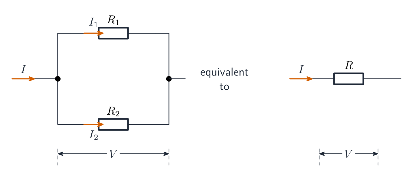
Reduce resistor networks to an equivalent resistance 等效电阻: series resistances add ($R_{\text{eq}}=R_1+R_2+\cdots$), while parallel resistances add as reciprocals ($\tfrac{1}{R_{\text{eq}}}=\tfrac{1}{R_1}+\tfrac{1}{R_2}+\cdots$ – always less than the smallest branch). Collapse the network step by step to find the battery current, then expand back out to find each element's current and voltage.

Worked example. A $12\ \text{V}$ battery drives a $4.0\ \Omega$ and a $2.0\ \Omega$ resistor in series: $R_{\text{eq}}=6.0\ \Omega$, $I=2.0\ \text{A}$, the voltages split $8.0\ \text{V}$ and $4.0\ \text{V}$, and the $4.0\ \Omega$ resistor dissipates $P=I^2R=16\ \text{W}$.

Real batteries are not ideal. Model a battery as an ideal battery 理想电池 of emf $\varepsilon$ in series with its own internal resistance 内阻 $r$. When current flows, some emf is used up inside, so the terminal voltage 端电压 – what a voltmeter across the battery actually reads – drops:

$$\Delta V_{\text{terminal}}=\varepsilon-Ir.$$

Worked example. A battery with $\varepsilon=12\ \text{V}$ and $r=0.50\ \Omega$ supplies $2.0\ \text{A}$: the terminals sit at $\Delta V=12-2.0(0.50)=11\ \text{V}$. With no current, a voltmeter reads the full $12\ \text{V}$.

Meters: an ammeter 电流表 goes in series at the point whose current you want (ideal ammeter: zero resistance); a voltmeter 电压表 goes in parallel across the element (ideal voltmeter: infinite resistance). Non-ideal meters disturb the circuit they measure – a real ammeter adds series resistance, a real voltmeter steals current.

ไทย

ลดเครือข่ายตัวต้านทานให้เป็น ความต้านทานสมมูล: ตัวต้านทานแบบ อนุกรม บวกกัน ($R_{\text{eq}}=R_1+R_2+\cdots$), ส่วนตัวต้านทานแบบ ขนาน บวกกันด้วยค่าผกผัน ($\tfrac{1}{R_{\text{eq}}}=\tfrac{1}{R_1}+\tfrac{1}{R_2}+\cdots$ – น้อยกว่าสาขาที่น้อยที่สุดเสมอ) รวมนetwork แบบขั้นตอนเพื่อหากระแสแบตเตอรี่ แล้วขยายกลับออกมาเพื่อหากระแสและแรงดันของแต่ละองค์ประกอบ

ตัวอย่างวิธีทำ. แบตเตอรี่ $12\ \text{V}$ ขับเคลื่อนตัวต้านทาน $4.0\ \Omega$ และ $2.0\ \Omega$ แบบอนุกรม: $R_{\text{eq}}=6.0\ \Omega$, $I=2.0\ \text{A}$, แรงดันแยกเป็น $8.0\ \text{V}$ และ $4.0\ \text{V}$, และตัวต้านทาน $4.0\ \Omega$ กระจายพลังงาน $P=I^2R=16\ \text{W}$.

ตัวต้านทานแบบขนานรวมกันเป็นความต้านทานสมมูลที่น้อยลง

แบตเตอรี่จริงไม่ใช่แบตเตอรี่ในอุดมคติ สร้างโมเดลแบตเตอรี่เป็น แบตเตอรี่ในอุดมคติ ที่มี emf $\varepsilon$ ต่ออนุกรมกับความต้านทานภายในของตัวเอง $r$ เมื่อมีกระแสไหล Some emf ถูกใช้ไปในภายใน, ดังนั้น แรงดันขั้ว – สิ่งที่โวลต์มิเตอร์วัดข้ามแบตเตอรี่ได้จริง – จะลดลง:

$$\Delta V_{\text{terminal}}=\varepsilon-Ir.$$

ตัวอย่างวิธีทำ. แบตเตอรี่ที่มี $\varepsilon=12\ \text{V}$ และ $r=0.50\ \Omega$ จ่าย $2.0\ \text{A}$: ขั้วอยู่ที่ $\Delta V=12-2.0(0.50)=11\ \text{V}$. เมื่อไม่มีกระแส โวลต์มิเตอร์จะอ่านค่าเต็ม $12\ \text{V}$.

มิเตอร์: แอมมิเตอร์ ต่อ แบบอนุกรม ที่จุดที่มีกระแสที่ต้องการ (แอมมิเตอร์ในอุดมคติ: ความต้านทานเป็นศูนย์); โวลต์มิเตอร์ ต่อ แบบขนาน ข้ามองค์ประกอบ (โวลต์มิเตอร์ในอุดมคติ: ความต้านทานเป็นอนันต์) มิเตอร์ที่ไม่ใช่ในอุดมคติรบกวนวงจรที่กำลังวัด – แอมมิเตอร์จริงเพิ่มความต้านทานแบบอนุกรม, โวลต์มิเตอร์จริงดึงกระแสไป

Vocabulary · ⁨คำศัพท์⁩ Train · ⁨ฝึกฝน⁩
English ไทย
parallel/ˈpærəlel/ 并联电路中
Resistance/rɪˈzɪstəns/ การต่อต้าน
11.6

Kirchhoff's Loop Rule · ⁨กฎวงจรรอบของเคอร์ชอฟฟ์⁩

Syllabus · ⁨หลักสูตร⁩
English

Learning Objective 11.6.A: Describe a circuit or elements of a circuit by applying Kirchhoff's loop rule.

  • 11.6.A.1 Energy changes in simple electrical circuits may be represented in terms of charges moving through electric potential differences within circuit elements.
    • Equation: $\Delta U_E = q\Delta V$
  • 11.6.A.2 Kirchhoff's loop rule is a consequence of the conservation of energy.
    • 11.6.A.2.i Kirchhoff's loop rule states that the sum of potential differences across all circuit elements in a single closed loop must equal zero.
      • Equation: $\sum \Delta V = 0$
    • 11.6.A.2.ii The values of electric potential at points in a circuit can be represented by a graph of electric potential as a function of position within a loop.
ไทย

วัตถุประสงค์การเรียนรู้ 11.6.A: อธิบายวงจรหรือองค์ประกอบของวงจรโดยใช้กฎลูปของคีร์ชฮอฟฟ์

  • 11.6.A.1 การเปลี่ยนแปลงพลังงานในวงจรรวมไฟฟ้าอย่างง่ายสามารถแสดงได้ในรูปของประจุที่เคลื่อนที่ผ่านความต่างศักย์ไฟฟ้าภายในองค์ประกอบของวงจร
    • สมการ: $\Delta U_E = q\Delta V$
  • 11.6.A.2 กฎลูปของคีร์ชฮอฟฟ์เป็นผลมาจากการอนุรักษ์พลังงาน
    • 11.6.A.2.i กฎลูปของเคอร์ชอฟฟ์ระบุว่าผลรวมของความต่างศักย์Acrossองค์ประกอบทั้งหมดในวงจรบนลูปปิดเดียวมีค่าเท่ากับศูนย์
      • สมการ: $\sum \Delta V = 0$
    • 11.6.A.2.ii ค่าศักย์ไฟฟ้าที่จุดต่างๆในวงจรสามารถแสดงได้ด้วยกราฟของศักย์ไฟฟ้าในฐานะฟังก์ชันของตำแหน่งภายในลูป

Source: College Board AP Course and Exam Description · ⁨แหล่งที่มา: คำอธิบายหลักสูตรและข้อสอบ College Board AP⁩

English

Charges moving through potential differences exchange energy ($\Delta U_E=q\Delta V$), and energy must balance around any closed path. That is Kirchhoff's loop rule 基尔霍夫回路定则:

$$\sum\Delta V=0\ \text{around any closed loop}.$$

Sign discipline wins these problems: crossing a battery from $-$ to $+$ is $+\varepsilon$; crossing a resistor with the assumed current is $-IR$ (against it, $+IR$). Write one equation per independent loop.

ไทย

ประจุที่เคลื่อนที่ผ่านผลต่างศักย์แลกเปลี่ยนพลังงาน ($\Delta U_E=q\Delta V$), และพลังงานต้องสมดุลรอบเส้นทางปิดใดๆ นั่นคือ กฎวงของเคอร์ชอฟฟ์:

$$\sum\Delta V=0\ \text{around any closed loop}.$$

วินัยเรื่องเครื่องหมายชนะโจทย์เหล่านี้: ผ่านแบตเตอรี่จาก $-$ ไป $+$ คือ $+\varepsilon$; ผ่าน resistor ตาม ทิศทางกระแสที่สมมติไว้คือ $-IR$ (ตรงข้ามกัน, $+IR$) เขียนสมการหนึ่งต่อหนึ่ง loop ที่ไม่ซ้ำกัน

11.7

Kirchhoff's Junction Rule · ⁨กฎจุดต่อของเคอร์ชอฟฟ์⁩

Syllabus · ⁨หลักสูตร⁩
English

Learning Objective 11.7.A: Describe a circuit or elements of a circuit by applying Kirchhoff's junction rule.

  • 11.7.A.1 Kirchhoff's junction rule is a consequence of the conservation of electric charge.
  • 11.7.A.2 Kirchhoff's junction rule states that the total amount of charge entering a junction per unit time must equal the total amount of charge exiting that junction per unit time.
    • Equation: $\sum I_{\text{in}} = \sum I_{\text{out}}$
ไทย

วัตถุประสงค์การเรียนรู้ 11.7.A: อธิบายวงจรหรือองค์ประกอบของวงจรโดยใช้กฎจุดต่อของคีร์ชฮอฟฟ์

  • 11.7.A.1 กฎจุดต่อของคีร์ชฮอฟฟ์เป็นผลมาจากการอนุรักษ์ประจุไฟฟ้า
  • 11.7.A.2 กฎจุดต่อของคีร์ชฮอฟฟ์ระบุว่าปริมาณประจุทั้งหมดที่เข้าสู่จุดต่อต่อหน่วยเวลาต้องเท่ากับปริมาณประจุทั้งหมดที่ออกจากจุดต่อนั้นต่อหน่วยเวลา
    • สมการ: $\sum I_{\text{in}} = \sum I_{\text{out}}$

Source: College Board AP Course and Exam Description · ⁨แหล่งที่มา: คำอธิบายหลักสูตรและข้อสอบ College Board AP⁩

English

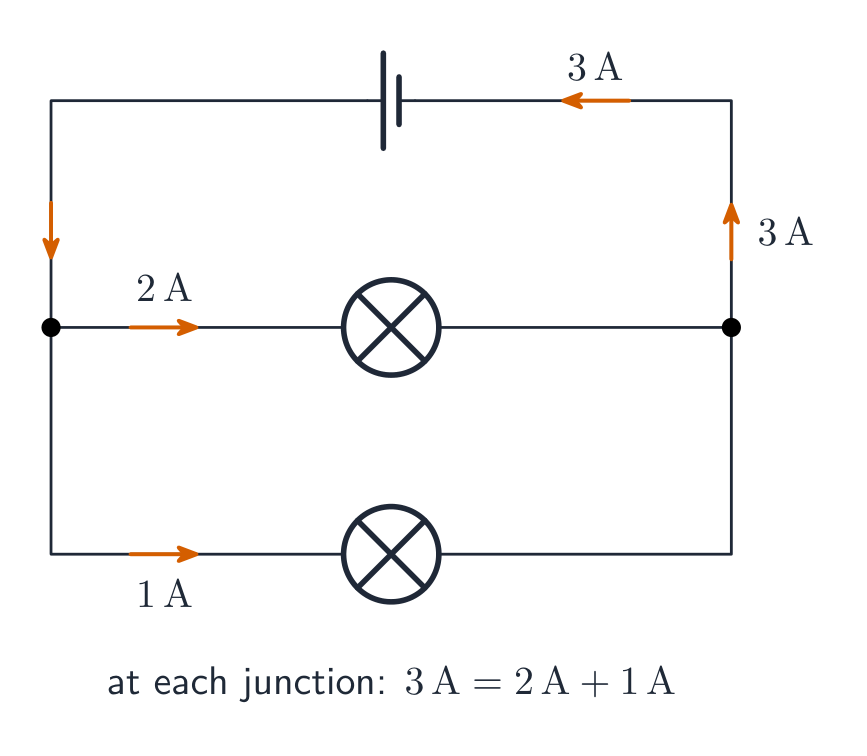
Kirchhoff's junction rule 基尔霍夫节点定则 is conservation of charge at a junction 节点:

$$\sum I_{\text{in}}=\sum I_{\text{out}}.$$

Together the two rules solve any multi-loop circuit: assign a current to each branch, write junction equations, then loop equations, and solve. A negative answer just means that current flows opposite to your assumed direction.

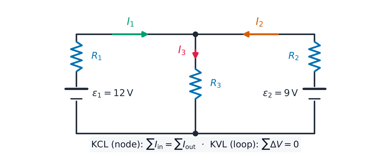
Worked example. In the circuit above, $\varepsilon_1=12\ \text{V}$ with $R_1=1.0\ \Omega$ on the left, $\varepsilon_2=9.0\ \text{V}$ with $R_2=1.0\ \Omega$ on the right, and a shared middle resistor $R_3=2.0\ \Omega$ carrying $I_3=I_1+I_2$ (junction rule). The two loop equations are

$$12=I_1+2(I_1+I_2)=3I_1+2I_2,\qquad 9=I_2+2(I_1+I_2)=2I_1+3I_2.$$

Solving: $I_1=3.6\ \text{A}$, $I_2=0.60\ \text{A}$, so $I_3=4.2\ \text{A}$ through the middle. Check with the second loop: $2(3.6)+3(0.60)=9.0$ ✓.

ไทย

กฎจุดต่อของเคอร์ชอฟฟ์ คือการอนุรักษ์ประจุที่ จุดต่อ:

$$\sum I_{\text{in}}=\sum I_{\text{out}}.$$
กระแสแยกที่จุดต่อ:สิ่งที่ไหลเข้าเท่ากับสิ่งที่ไหลออก

ทั้งสองกฎร่วมกันแก้วงจรหลายวงได้ทุกชนิด: กำหนดกระแสให้แต่ละสาขา, เขียนสมการจุดต่อ, จากนั้นสมการวง, และแก้สมการ คำตอบติดลบหมายความว่ากระแสไหลทวนทิศทางที่คุณสมมติไว้

สมการวงสองสมการและสมการจุดต่อหนึ่งสมการแก้วงจรแบตเตอรี่สองตัวนี้

ตัวอย่างวิธีทำ. ในวงจรข้างต้น, $\varepsilon_1=12\ \text{V}$ พร้อม $R_1=1.0\ \Omega$ ทางซ้าย, $\varepsilon_2=9.0\ \text{V}$ พร้อม $R_2=1.0\ \Omega$ ทางขวา, และตัวต้านทานกลาง shared $R_3=2.0\ \Omega$ Mangsten $I_3=I_1+I_2$ (กฎจุดเชื่อมต่อ) สมการสอง loop คือ

$$12=I_1+2(I_1+I_2)=3I_1+2I_2,\qquad 9=I_2+2(I_1+I_2)=2I_1+3I_2.$$

การแก้: $I_1=3.6\ \text{A}$, $I_2=0.60\ \text{A}$, ดังนั้น $I_3=4.2\ \text{A}$ ผ่านทางกลาง ตรวจสอบด้วยวงที่สอง: $2(3.6)+3(0.60)=9.0$ ✓.

11.8

Resistor-Capacitor (RC) Circuits · ⁨วงจรตัวต้านทาน-ตัวเก็บประจุ (RC)⁩

Syllabus · ⁨หลักสูตร⁩
Learning ObjectiveEssential Knowledge

11.8.A
Describe the equivalent capacitance of multiple capacitors.

  • 11.8.A.1 A collection of capacitors in a circuit may be analyzed as though it was a single capacitor with an equivalent capacitance $C_{\text{eq}}$.
    • 11.8.A.1.i The inverse of the equivalent capacitance of a set of capacitors connected in series is equal to the sum of the inverses of the individual capacitances.
      • Equation: $\dfrac{1}{C_{\text{eq},s}} = \sum_{i} \dfrac{1}{C_i}$
    • 11.8.A.1.ii The equivalent capacitance of a set of capacitors in series is less than the capacitance of the smallest capacitor.
    • 11.8.A.1.iii The equivalent capacitance of a set of capacitors in parallel is the sum of the individual capacitances.
      • Equation: $C_{\text{eq},p} = \sum_{i} C_i$
  • 11.8.A.2 As a result of conservation of charge, each of the capacitors in series must have the same magnitude of charge on each plate.

11.8.B
Describe the behavior of a circuit containing combinations of resistors and capacitors.

  • 11.8.B.1 The charge on a capacitor or the current in a resistor in an RC circuit can be described by a fundamental differential equation derived from Kirchhoff's loop rule.
    • Equation: $\mathcal{E} = \dfrac{dq}{dt}R + \dfrac{q}{C}$
  • 11.8.B.2 The time constant ($\tau$) is a significant feature of an RC circuit.
    • 11.8.B.2.i The time constant of an RC circuit is a measure of how quickly the capacitor will charge or discharge and is defined as $\tau = R_{\text{eq}}C_{\text{eq}}$.
    • 11.8.B.2.ii For a charging capacitor, the time constant represents the time required for the capacitor's charge to increase from zero to approximately 63 percent of its final asymptotic value.
    • 11.8.B.2.iii For a discharging capacitor, the time constant represents the time required for the capacitor's charge to decrease from fully charged to approximately 37 percent of its initial value.
  • 11.8.B.3 The potential difference across a capacitor and the current in the branch of the circuit containing the capacitor each change over time as the capacitor charges and discharges, but both will reach a steady state after a long time interval.
    • 11.8.B.3.i Immediately after being placed in a circuit, an uncharged capacitor acts like a wire, and charge can easily flow to or from the plates of the capacitor.
    • 11.8.B.3.ii As a capacitor charges, changes to the potential difference across the capacitor affect the charge on the plates of the capacitor, the current in the circuit branch in which the capacitor is located, and the electric potential energy stored in the capacitor.
    • 11.8.B.3.iii The potential difference across a capacitor, the current in the circuit branch in which the capacitor is located, and the electric potential energy stored in the capacitor all change with respect to time and asymptotically approach steady state conditions.
    • 11.8.B.3.iv After a long time, a charging capacitor approaches a state of being fully charged, reaching a maximum potential difference at which there is zero current in the circuit branch in which the capacitor is located.
    • 11.8.B.3.v Immediately after a charged capacitor begins discharging, the amount of charge on the capacitor and the energy stored in the capacitor begin to decrease.
    • 11.8.B.3.vi As a capacitor discharges, the amount of charge on the capacitor, the potential difference across the capacitor, and the current in the circuit branch in which the capacitor is located all decrease until a steady state is reached.
    • 11.8.B.3.vii After either charging or discharging for times much greater than the time constant, the capacitor and the relevant circuit branch may be modeled using steady-state conditions.

Source: College Board AP Course and Exam Description · ⁨แหล่งที่มา: คำอธิบายหลักสูตรและข้อสอบ College Board AP⁩

English
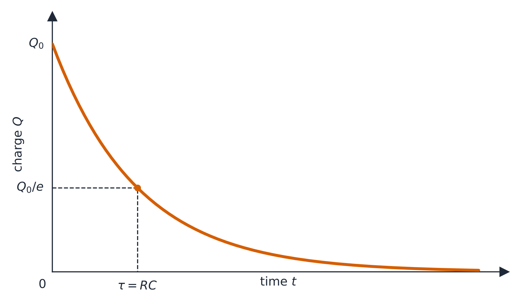
Discharging a capacitor: τ = RC
Charging a capacitor (RC)

Capacitor networks reduce like resistors but with the rules swapped: parallel capacitances add ($C_{\text{eq}}=C_1+C_2$), series add as reciprocals – and capacitors in series must carry the same charge on each plate, by conservation of charge. Use the equivalent capacitance 等效电容 to analyse the network, then expand back.

In an RC circuit RC电路, Kirchhoff's loop rule gives the differential equation

$$\varepsilon=R\frac{dq}{dt}+\frac{q}{C},$$

whose solutions are exponentials with time constant 时间常数 $\tau=RC$:

$$q(t)=Q\big(1-e^{-t/RC}\big)\ \text{(charging)},\qquad q(t)=Q\,e^{-t/RC}\ \text{(discharging)},\qquad i(t)=\frac{\varepsilon}{R}e^{-t/RC}.$$

The current is largest at the first instant and decays – it never "waits" for the capacitor. Learn the two limits: at $t=0$ an uncharged capacitor acts like a plain wire (maximum current); after a long time it is fully charged, no current flows in its branch, and it acts like a break. In any steady state 稳态, cover the capacitor branch with your finger, solve the resistor circuit, then read the capacitor's voltage from the element it sits across.

Worked example. With $R=5.0\ \text{k}\Omega$, $C=200\ \mu\text{F}$, and a $10\ \text{V}$ battery: $\tau=RC=1.0\ \text{s}$; initial current $\dfrac{\varepsilon}{R}=2.0\ \text{mA}$; after one time constant the charge is $q=CV(1-e^{-1})\approx1.3\times10^{-3}\ \text{C}$, about $63\%$ of full charge, and the current has fallen to $37\%$ of its initial value.

ไทย
การคายประจุของตัวเก็บประจุ: τ = RC
การชาร์จตัวเก็บประจุ (RC)

เครือข่ายตัวเก็บประจุลดรูปเหมือนตัวต้านทานแต่สลับกฎ: ความจุแบบขนานบวกกัน ($C_{\text{eq}}=C_1+C_2$), แบบอนุกรมบวกกันด้วยค่าผกผัน – และตัวเก็บประจุแบบอนุกรมต้องมี ประจุเดียวกัน บนแต่ละแผ่น, โดยหลักการอนุรักษ์ประจุ ใช้ ความจุสมมูล เพื่อวิเคราะห์ network แล้วขยายกลับ

ใน วง RC RC, กฎวงของเคอร์ชอฟฟ์ให้สมการเชิงอนุพันธ์

$$\varepsilon=R\frac{dq}{dt}+\frac{q}{C},$$

ซึ่งคำตอบเป็นฟังก์ชันเอกซ์โพเนนเชียลที่มี ค่าคงที่เวลา $\tau=RC$:

$$q(t)=Q\big(1-e^{-t/RC}\big)\ \text{(charging)},\qquad q(t)=Q\,e^{-t/RC}\ \text{(discharging)},\qquad i(t)=\frac{\varepsilon}{R}e^{-t/RC}.$$

กระแสมีค่ามากที่สุดในช่วงแรกแล้วลดลง – มันไม่ "รอ" ให้ตัวเก็บประจุ learning了两个极限: ที่ $t=0$ ตัวเก็บประจุที่ไม่มีประจุ behaves like a plain wire (maximum current); หลังจากระยะเวลานานมันจะถูกชาร์จเต็ม, ไม่มีกระแสไหลในสาขาของมัน, และ behaves like a break. ใน任何 steady state, ******************** capacitor branch with your finger, solve the resistor circuit, then read the capacitor's voltage from the element it sits across.

ประจุบนตัวเก็บประจุลดลงแบบเอ็กซ์โพเนนเชียลขณะคายประจุ

ตัวอย่างวิธีทำ. ด้วย $R=5.0\ \text{k}\Omega$, $C=200\ \mu\text{F}$, และแบตเตอรี่ $10\ \text{V}$: $\tau=RC=1.0\ \text{s}$; กระแสเริ่มต้น $\dfrac{\varepsilon}{R}=2.0\ \text{mA}$; หลังหนึ่ง time constant ประจุคือ $q=CV(1-e^{-1})\approx1.3\times10^{-3}\ \text{C}$, ประมาณ $63\%$ ของประจุเต็ม, และกระแสลดลงเหลือ $37\%$ ของค่าเริ่มต้น

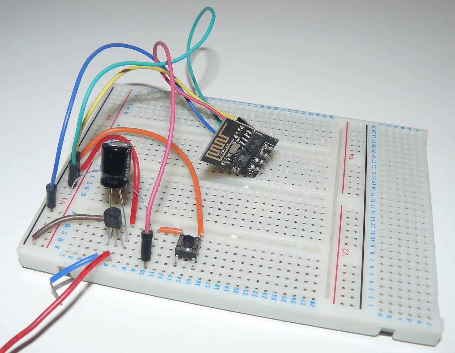
วงจรอิเล็กทรอนิกส์ที่สร้างบนบอร์ดทดลอง
วงจรจริงบนบอร์ดทดลอง: ตัวต้านทานและตัวเก็บประจุร่วมกันกำหนดความเร็วในการเพิ่มขึ้นและลดลงของแรงดันไฟฟ้า
Vocabulary · ⁨คำศัพท์⁩ Train · ⁨ฝึกฝน⁩
English ไทย
time constant/taɪm ˈkɒnstənt/ ค่าคงที่เวลา
steady state/ˈstedi steɪt/ สถานะคงที่
11.8

Exam tips · ⁨ข้อแนะนำสำหรับการสอบ⁩

English
  • Relate current to charge flow $I=\tfrac{dQ}{dt}$ and use $J=\sigma E$, $R=\tfrac{\rho L}{A}$ for resistance.
  • Apply Kirchhoff's laws (junction: charge; loop: energy) with consistent sign conventions.
  • Analyse RC circuits with calculus: charging/discharging give exponentials with time constant $\tau=RC$.
  • Combine resistors (series add, parallel reciprocal) and track power $P=IV=I^2R$.
  • At $t=0$ a capacitor acts like a wire; after a long time ($t\to\infty$) it acts like an open branch.
ไทย
  • เชื่อมโยงกระแสไฟฟ้ากับการไหลของประจุ $I=\tfrac{dQ}{dt}$ และใช้ $J=\sigma E$, $R=\tfrac{\rho L}{A}$ สำหรับความต้านทาน
  • ใช้ กฎของเคอร์ชอฟฟ์ (จุดต่อ: ประจุ; ลูป: พลังงาน) พร้อมเครื่องหมายที่สอดคล้องกัน
  • วิเคราะห์ วงจร RC ด้วยแคลคูลัส: การชาร์จ/การคายประจุให้กราฟเอกซ์โพเนนเชียลที่มีค่าคงที่เวลา $\tau=RC$
  • รวมตัวต้านทาน (แบบอนุกรมบวกกัน, แบบขนานหาส่วนกลับ) และติดตามกำลัง $P=IV=I^2R$
  • ที่ $t=0$ ตัวเก็บประจุ behaves เหมือนสายไฟ; หลังผ่านไปนาน ($t\to\infty$) จะ behaves เหมือนวงจรเปิด

Interactive lessons on this topic · ⁨บทเรียนเชิงโต้ตอบสำหรับหัวข้อนี้⁩

Work through it step by step, with instant-check exercises. · ⁨ทำทีละขั้นตอน พร้อมแบบฝึกหัดตรวจสอบผลทันที⁩

Past Papers · ⁨ข้อสอบย้อนหลัง⁩

More topics in AP Physics C: Electricity and Magnetism · ⁨หัวข้อเพิ่มเติมใน AP Physics C: Electricity and Magnetism⁩

Log in or create account · ⁨เข้าสู่ระบบหรือสร้างบัญชี⁩

IGCSE, A-Level & AP