| Learning Objective | Essential Knowledge |
|---|---|
13.1.A |
|
Electromagnetic Induction
AP Physics C: Electricity and Magnetism · Topic 13
 9:11
9:11
Electromagnetic Induction
Almost every watt of electricity you have ever used began the same way, with a magnet and a coil of wire moving past each other. No fuel, no burning: only…
English narration · English + 中文 subtitles burned in
13.1
Magnetic Flux
Syllabus
Source: College Board AP Course and Exam Description
Magnetic flux 磁通量 measures how much magnetic field passes through a surface. For a uniform field through a flat loop it is the dot product $\Phi_B=\vec{B}\cdot\vec{A}=BA\cos\theta$; in general it is the surface integral 面积分
$$\Phi_B=\int \vec{B}\cdot d\vec{A}.$$
The area vector 面积矢量 is perpendicular to the surface (outward from a closed one), and the sign of the flux comes from the dot product. Flux changes if $B$ changes, the area changes, or the loop turns – keep all three routes in mind, because each one is an exam question.
Vocabulary
Train
| English |
|---|
| Magnetic flux/mæɡˈnetɪk flʌks/ |
| surface integral/ˈsɜːfɪs ˈɪntɪɡrəl/ |
| area vector/ˈeərɪə ˈvektə/ |
13.2
Electromagnetic Induction
Syllabus
| Learning Objective | Essential Knowledge |
|---|---|
13.2.A |
Boundary statement: AP Physics C: Electricity & Magnetism does not expect students to mathematically derive the speed of light in free space from Maxwell's equations. This relationship is included above solely as an indication of the further applications, implications, and connections to physical phenomena that students may study in more advanced physics courses. |
Source: College Board AP Course and Exam Description
A changing flux induces an emf 电动势 – Faraday's law 法拉第定律:
$$\varepsilon=-\frac{d\Phi_B}{dt}.$$
With constant area, $\varepsilon=-A\,\dfrac{dB_\perp}{dt}$; with constant field, $\varepsilon=-B\,\dfrac{dA_\perp}{dt}$. A coil of $N$ turns multiplies the single-loop emf: $|\varepsilon_{\text{sol}}|=N\left|\dfrac{d\Phi_B}{dt}\right|$.
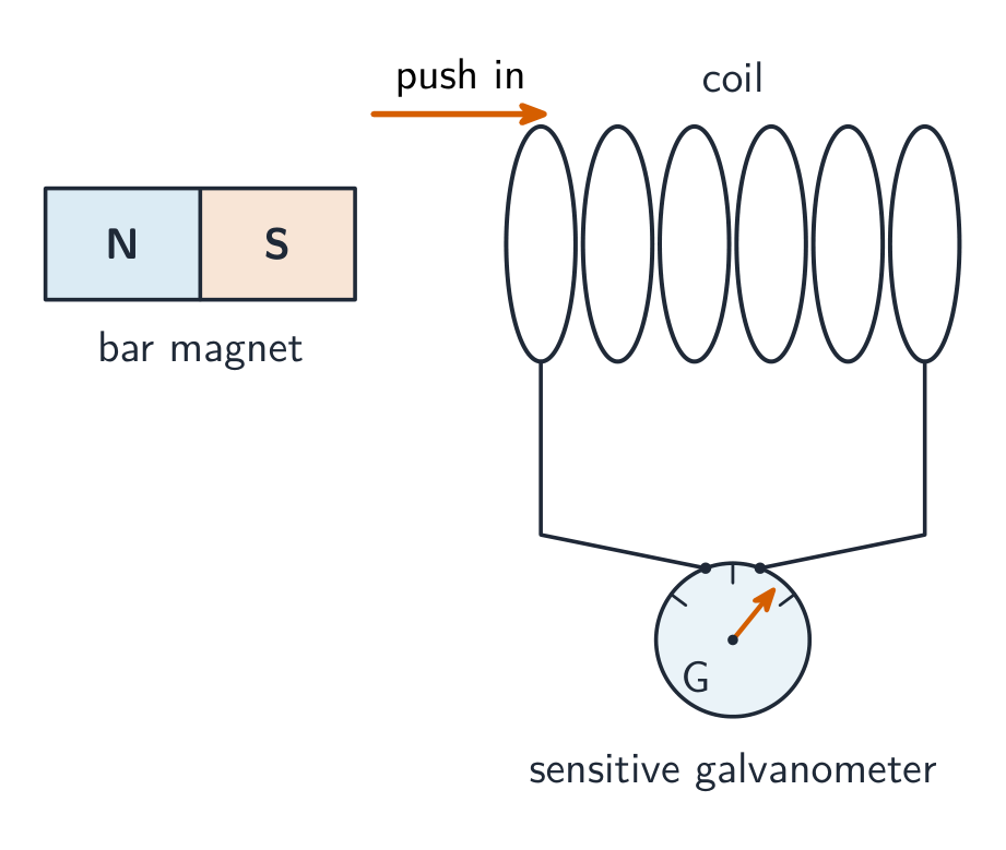
Lenz's law 楞次定律 is the minus sign: the induced current 感应电流 flows so that its own magnetic field opposes the change in flux that created it. Push a magnet toward a loop and the loop pushes back; pull it away and the loop pulls it in. Use the right-hand rule 右手定则 to turn "oppose the change" into a current direction.
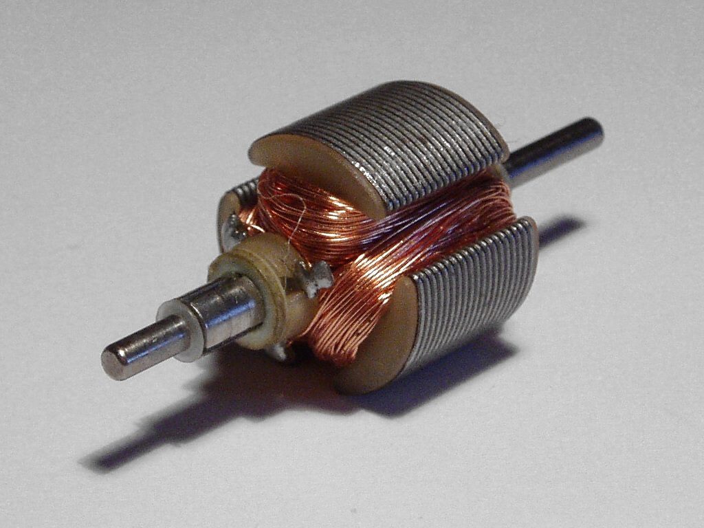
A rod of length $L$ sliding at speed $v$ across a field is the special case worth memorising – the motional emf 动生电动势 $\varepsilon=BLv$.
Worked example. A $0.20\ \text{m}$ rod slides at $3.0\ \text{m/s}$ across a $0.50\ \text{T}$ field: $\varepsilon=BLv=0.50(0.20)(3.0)=0.30\ \text{V}$. Equivalently, if a single loop's flux drops from $0.020\ \text{Wb}$ to $0.008\ \text{Wb}$ in $0.030\ \text{s}$, the average emf is $\varepsilon=\dfrac{0.012}{0.030}=0.40\ \text{V}$.
Faraday's law is also the third of Maxwell's equations 麦克斯韦方程组, in a deeper form: a changing magnetic flux creates a circulating electric field, $\oint\vec{E}\cdot d\vec{l}=-\dfrac{d\Phi_B}{dt}$ – that field is what pushes the charges around the loop. Together, Maxwell's equations predict electromagnetic waves 电磁波 travelling at $c=1/\sqrt{\varepsilon_0\mu_0}$ (you should know this connection, but AP will not ask you to derive it).
Explore
Induce a current by moving a magnet
A changing magnetic flux through a coil induces an EMF (Faraday's law); its direction opposes the change (Lenz's law). Move the magnet faster for a bigger EMF.
Vocabulary
Train
| English |
|---|
| emf/emf/ |
| Faraday's law/ˈfærədeɪz lɔː/ |
| Lenz's law/ˈlentsɪz lɔː/ |
| induced current/ɪnˈdjuːst ˈkʌrənt/ |
| right-hand rule/raɪt hænd ruːl/ |
| motional emf/ˈməʊʃənl emf/ |
| Maxwell's equations/ˈmækswelz ɪˈkweɪʒnz/ |
| electromagnetic waves/ɪˌlektrəʊməɡˈnetɪk weɪvz/ |
13.3
Induced Currents and Magnetic Forces
Syllabus
| Learning Objective | Essential Knowledge |
|---|---|
13.3.A |
|
Source: College Board AP Course and Exam Description
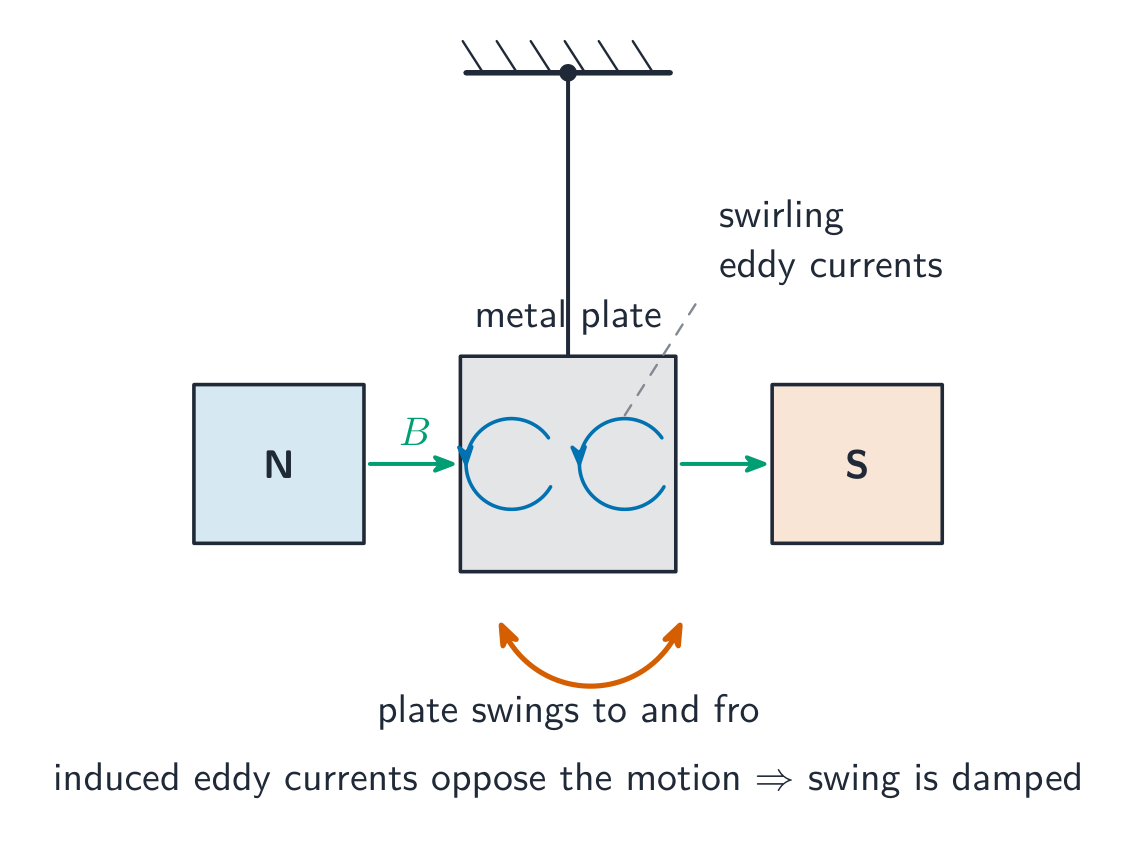
Once an induced current flows, the external field exerts forces on it ($\vec{F}=\int I\,d\vec{l}\times\vec{B}$) – and by Lenz's law those forces always resist the motion that causes the induction. Only the segments of the loop actually inside the field feel a force, which can make a loop accelerate, rotate, or brake. This is the origin of eddy currents 涡电流 braking, and you can apply Newton's second law to a moving loop or rod like any other mechanics problem.
The classic setup is a rod sliding on conducting rails connected by a resistor:

Worked example (the full chain). Rails $L=0.20\ \text{m}$ apart with resistance $R=0.60\ \Omega$ sit in a $0.50\ \text{T}$ field into the page. The rod is pushed at a constant $3.0\ \text{m/s}$. Then: $\varepsilon=BLv=0.30\ \text{V}$; $I=\varepsilon/R=0.50\ \text{A}$; the field pushes back on the rod with $F=BIL=0.50(0.50)(0.20)=0.050\ \text{N}$. The pushing force does work at $P=Fv=0.15\ \text{W}$ – exactly the $P=I^2R=0.15\ \text{W}$ dissipated in the resistor. Mechanical work becomes electrical energy: that is a generator 发电机, and energy is conserved. Released with no push, the rod slows exponentially: $ma=-\dfrac{B^2L^2}{R}v$.
Exam skill. FRQs walk this exact chain: flux $\to$ emf $\to$ current $\to$ force $\to$ Newton's second law. Write each link separately and check the direction with Lenz's law at the end.
Vocabulary
Train
| English |
|---|
| eddy currents/ˈedi ˈkʌrənts/ |
| generator/ˈdʒenəreɪtə/ |
13.4
Inductance
Syllabus
| Learning Objective | Essential Knowledge |
|---|---|
13.4.A |
|
Source: College Board AP Course and Exam Description
Inductance 电感 is a conductor's tendency to oppose a change in its own current: changing current changes its own flux, which self-induces an emf. From Faraday's law,
$$\varepsilon=-L\frac{dI}{dt}.$$
An inductor 电感器 is a circuit element built to have large inductance – usually a solenoid 螺线管, where geometry gives
$$L_{\text{sol}}=\frac{\mu_{\text{core}}N^2A}{\ell},$$
with $N$ total turns, area $A$, length $\ell$, and the magnetic permeability 磁导率 of the core. (Straight wires are modelled as having zero inductance.) An inductor carrying current $I$ stores energy in its magnetic field:
$$U_L=\tfrac{1}{2}LI^2,$$
which can later be dissipated in a resistor or moved into a capacitor – conservation of energy applies as usual.
Vocabulary
Train
| English |
|---|
| inductance/ɪnˈdʌktəns/ |
| inductor/ɪnˈdʌktə/ |
| solenoid/ˈsəʊlənɔɪd/ |
| magnetic permeability/mæɡˈnetɪk ˌpɜːməˈbɪlɪti/ |
13.5
Circuits with Resistors and Inductors
Syllabus
| Learning Objective | Essential Knowledge |
|---|---|
13.5.A |
|
Source: College Board AP Course and Exam Description
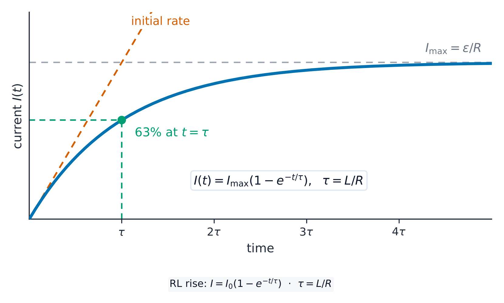
In an RL circuit RL电路, Kirchhoff's loop rule for a battery $\varepsilon$, resistor $R$, and inductor $L$ in series gives a differential equation 微分方程:
$$\varepsilon=IR+L\frac{dI}{dt}\quad\Rightarrow\quad I(t)=\frac{\varepsilon}{R}\big(1-e^{-t/\tau}\big),\qquad \tau=\frac{L}{R}.$$
The time constant 时间常数 $\tau$ sets the pace: after one $\tau$ a rising current reaches about $63\%$ of its final value (a decaying one falls to $37\%$); it is also how long the change would take at the initial rate. Learn the two limits – they answer most conceptual questions:
- Just after the switch closes ($t=0$): current cannot jump, so the inductor momentarily blocks it, self-inducing an emf equal and opposite to the applied potential difference.
- Long after ($t\gg\tau$): the current is steady, $dI/dt=0$, and the inductor behaves as a plain wire – the exact opposite of a capacitor.
Worked example. $\varepsilon=12\ \text{V}$, $R=6.0\ \Omega$, $L=3.0\ \text{H}$: final current $\varepsilon/R=2.0\ \text{A}$, $\tau=L/R=0.50\ \text{s}$. At $t=0.50\ \text{s}$ the current is $2.0(1-e^{-1})\approx1.3\ \text{A}$. At $t=0$ the inductor's potential difference is the full $12\ \text{V}$; as $t\to\infty$ it falls to zero. Current, inductor voltage, and stored energy are all exponential in time.
Vocabulary
Train
| English |
|---|
| RL circuit/ˌɑː ˈel ˈsɜːkɪt/ |
| differential equation/ˌdɪfəˈrenʃl ɪˈkweɪʒn/ |
| time constant/taɪm ˈkɒnstənt/ |
13.6
Circuits with Capacitors and Inductors
Syllabus
| Learning Objective | Essential Knowledge |
|---|---|
13.6.A |
|
Source: College Board AP Course and Exam Description
An LC circuit LC电路 has no resistance, so nothing dissipates energy: it oscillates 振荡, sloshing energy between the capacitor's electric field and the inductor's magnetic field. The loop rule gives
$$\frac{d^2q}{dt^2}=-\frac{1}{LC}\,q,$$
the same equation as a mass on a spring – simple harmonic motion 简谐运动 with charge playing the role of displacement and
$$\omega=\frac{1}{\sqrt{LC}}.$$
The total energy $\dfrac{q^2}{2C}+\tfrac12LI^2$ stays constant: all in the capacitor at maximum charge, all in the inductor at maximum current.
Worked example. $L=2.0\ \text{H}$, $C=8.0\ \mu\text{F}$: $\omega=\dfrac{1}{\sqrt{2.0(8.0\times10^{-6})}}=250\ \text{rad/s}$, period $T=2\pi/\omega\approx0.025\ \text{s}$. If the capacitor starts charged to $12\ \text{V}$, then $U=\tfrac12CV^2=5.8\times10^{-4}\ \text{J}$, and the maximum current follows from $\tfrac12LI_{\max}^2=U$: $I_{\max}=\sqrt{2U/L}=0.024\ \text{A}$ – conservation of energy 能量守恒, no calculus needed.
Vocabulary
Train
| English |
|---|
| LC circuit/ˌel ˈsiː ˈsɜːkɪt/ |
| oscillates/ˈɒsɪleɪts/ |
| simple harmonic motion/ˈsɪmpl hɑːˈmɒnɪk ˈməʊʃn/ |
| conservation of energy/ˌkɒnsəˈveɪʃn ɒv ˈenədʒi/ |
13.6
Exam tips
- Compute flux $\Phi_B=\int \vec B\cdot d\vec A$ and get the induced EMF from Faraday's law $\varepsilon=-\tfrac{d\Phi_B}{dt}$.
- Use Lenz's law (the minus sign) to fix the direction: the induced current opposes the change in flux.
- Flux changes three ways — changing $B$, changing area, or changing angle — identify which and differentiate.
- For a rod of length $L$ moving at speed $v$, the motional EMF is $BLv$.
- An inductor stores energy $\tfrac12 LI^2$ and resists changes in current (RL time constant $\tau=L/R$).
Interactive lessons on this topic
Work through it step by step, with instant-check exercises.