A student measures the resistance of a light-emitting diode (LED) when the current in it changes.
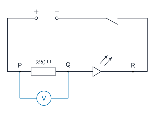
The student sets up the circuit shown in Fig. 2.1.

The student:
- connects a voltmeter to measure the potential difference across the 220 $\Omega$ resistor
- closes the switch
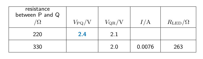
- records the voltmeter reading $V_{PQ}$ in the top row of Table 2.1
- opens the switch.
On Fig. 2.1, draw the symbol for a voltmeter connected to measure the potential difference across the 220 $\Omega$ resistor.[2]
The voltmeter reading is shown in Fig. 2.2.

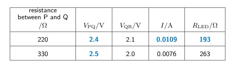
Write down the reading in the top row of Table 2.1 under the heading $V_{PQ}$.[1]
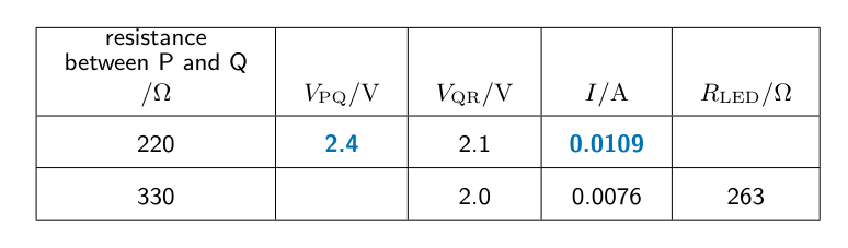
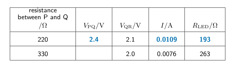
| resistance between P and Q /$\Omega$ | $V_{PQ}$ /V | $V_{QR}$ /V | $I$ /A | $R_{LED}$ /$\Omega$ |
| 220 | 2.1 | |||
| 330 | 2.0 | 0.0076 | 263 |
Table 2.1
The student:
- disconnects the voltmeter from points P and Q
- reconnects the voltmeter across the LED between points Q and R
- closes the switch.
- records the voltmeter reading $V_{QR}$ in the top row of Table 2.1
- opens the switch.
Calculate the current $I$ in the circuit in part (a) using the equation
$I = \frac{V_{PQ}}{R}$
where $R = 220 \Omega$.
Record your answer in the top row of Table 2.1.[1]
Calculate the resistance $R_{LED}$ of the LED using the equation
$R_{LED} = \frac{V_{QR}}{I}$
Record your answer to a suitable number of significant figures for this experiment in the top row of Table 2.1.[2]
The student:
- removes the 220 $\Omega$ resistor from the circuit and replaces it with a 330 $\Omega$ resistor
- reconnects the voltmeter across the resistor between points P and Q
- repeats parts (a) to (c) for the 330 $\Omega$ resistor.
Use the information in Table 2.1 to calculate the value of the potential difference $V_{PQ}$ across the 330 $\Omega$ resistor.
Show your working and record your answer in Table 2.1.[1]
As the resistance between points P and Q changes, the current in the circuit changes.
Use your results in Table 2.1 to write a conclusion, stating how the change in current affects the potential difference $V_{QR}$ across the LED and the resistance $R_{LED}$ of the LED.[2]
Another student uses a variable resistor to control the current in the circuit.
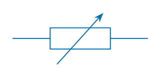
Draw the symbol for a variable resistor.[1]
Explain one advantage of using a variable resistor for this purpose rather than the procedure carried out in (a) and (b).[1]