In this experiment, you will investigate the resistance of a light-emitting diode (LED) when the current in it changes.
The supervisor has set up the circuit as shown in Fig. 2.1.

• Close the switch.
Record the voltmeter reading $V_{PQ}$ across the $220\,\Omega$ resistor in the top row of Table 2.1.
- Open the switch. [1]
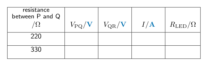
Table 2.1
| resistance between P and Q /$\Omega$ | $V_{PQ}$/ | $V_{QR}$/ | $I$/ | $R_{LED}$/$\Omega$ |
| 220 | ||||
| 330 |
• Disconnect the voltmeter from points P and Q.
- Reconnect the voltmeter across the LED between points Q and R.
- Ensure that the positive terminal of the voltmeter is connected to Q.
- Close the switch.
Record the voltmeter reading $V_{QR}$ in the top row of Table 2.1.
- Open the switch. [1]
Calculate the current $I$ in the circuit in part (a) using the equation
$I = \frac{V_{PQ}}{R}$
where $R = 220\,\Omega$.
Record your answer in the top row of Table 2.1.[1]
Calculate the resistance $R_{LED}$ of the LED using the equation
$R_{LED} = \frac{V_{QR}}{I}$
Record your answer to a suitable number of significant figures for this experiment in the top row of Table 2.1.[2]
Complete the column headings in Table 2.1 by inserting the missing units.[1]
• Remove the $220\,\Omega$ resistor from the circuit and replace it with the $330\,\Omega$ resistor.
- Reconnect the voltmeter across the resistor between points P and Q. Ensure that the positive terminal is connected to P.
Repeat parts (a) to (d) for the $330\,\Omega$ resistor.[2]
As the resistance between terminals P and Q changes, the current in the circuit changes.
Use your results in Table 2.1 to write a conclusion, stating how the change in current affects the voltmeter reading $V_{QR}$ across the LED and the resistance $R_{LED}$ of the LED.[2]
A student attempts to set up the circuit shown in Fig. 2.1. The student finds that when the switch is closed, the LED does not light up.
Suggest what the student may have done incorrectly while setting up the circuit.[1]
[Total: 11]