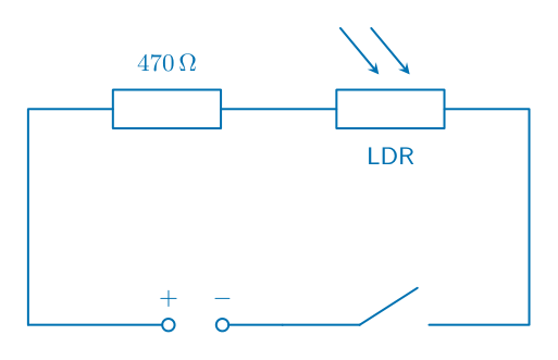
In this experiment, you will investigate a light-dependent resistor (LDR).
You are provided with a series circuit consisting of a power supply, a switch, a 470 $\Omega$ resistor and an LDR.
Draw a circuit diagram of the circuit that has been set up for you. Choose symbols from the list in Fig. 2.1.

[2]
• Close the switch.
- Connect the voltmeter between points X and Y.
Record the voltmeter reading $V_{XY}$.
$V_{XY} =$ $V$[1]
• Connect the voltmeter between points Y and Z.
Record the voltmeter reading $V_{YZ}$.
$V_{YZ} =$ $V$
- Open the switch. [1]
The current $I$ in the circuit is calculated using the equation:
$I = \frac{V_{XY}}{R}$
where $R = 470 \Omega$.
Use your voltmeter reading in (b)(i) to calculate the current $I$.
$I =$ $A$[1]
The resistance of the LDR is calculated using the equation:
$R = \frac{V_{YZ}}{I}$
Use your voltmeter reading in (b)(ii) to calculate the resistance $R$ of the LDR.
$R =$ $\Omega$[1]
• Disconnect the voltmeter from points Y and Z.
- Place the piece of card on top of the LDR.
Repeat the measurements made in (b).
$V_{XY} =$ $V$
$V_{YZ} =$ $V$[1]
• Ensure that the voltmeter is connected between points Y and Z.
- Close the switch.
- Hold the card horizontally about 50 cm above the LDR.
- Slowly move the card towards the LDR until it rests on top of the LDR.
- Observe the reading on the voltmeter as you move the card.
Describe your observations.[1]
When the LDR is covered by the card, the current in the circuit changes.
Use your results in (b) and (d) to state how this change in current affects the total potential difference ($V_{XY} + V_{YZ}$).[1]
Compare your value for the potential difference $V_{YZ}$ across the LDR in bright light in (b) with the value for the potential difference $V_{YZ}$ across the LDR in the dark in (d).
Suggest what causes the change in the readings as the intensity of the light reaching the LDR decreases.[1]
[Total: 10]