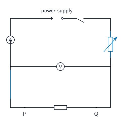
In this experiment, you will investigate a circuit containing different combinations of resistors. The circuit has been set up for you. Carry out the following instructions, referring to Fig. 2.1.

Switch on.
Measure the potential difference $V_1$ and the current $I_1$ in the circuit.
$V_1 =$
$I_1 =$ [1]
Switch off.
Calculate a resistance $R_1$ using your values from (a)(i) and the equation $R_1 = \frac{V_1}{I_1}$.
$R_1 =$ [1]
Connect both resistors in series between terminals P and Q as shown in Fig. 2.2.

Switch on.
Measure the potential difference $V_2$ and the current $I_2$ in the circuit.
$V_2 =$
$I_2 =$ [1]
Switch off.
Calculate a resistance $R_2$ using your values from (b)(i) and the equation $R_2 = \frac{V_2}{(I_2 \times 2)}$.
$R_2 =$ [1]
Connect both resistors in parallel between terminals P and Q as shown in Fig. 2.3.

Switch on.
Measure the potential difference $V_3$ and the current $I_3$ in the circuit.
$V_3 =$
$I_3 =$ [1]
Switch off.
Calculate a resistance $R_3$ using your values from (c)(i) and the equation $R_3 = \frac{(V_3 \times 2)}{I_3}$.
$R_3 =$ [1]
A student suggests that $R_1$, $R_2$ and $R_3$ should be equal. State whether your results support this suggestion. Justify your statement with reference to your results.
statement
justification [2]
A student wants to determine $R_1$ by using a variable resistor to control the current in the circuit. Complete the circuit in Fig. 2.4 to show a variable resistor connected for this purpose. You are not required to do this experiment.

[2]
Briefly explain how using the circuit in Fig. 2.4 will give a more reliable value for $R_1$ than using the procedure you were asked to carry out in (a).[1]
[Total: 11]