In this experiment, you will investigate circuits containing different combinations of three resistors connected between terminals P and Q.
Circuit A has been set up for you. It is shown in Fig. 2.1.
The protective resistor must remain in place throughout the experiment.

Circuit A
Close the switch.
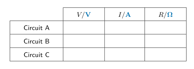
Measure and record in Table 2.1:
- the potential difference (p.d.) $V$ across terminals P and Q
- the current $I$ in the circuit.
[3]
Open the switch.
Table 2.1
| $V /$ | $I /$ | $R /$ | |
| Circuit A | |||
| Circuit B | |||
| Circuit C |
Calculate and record in Table 2.1 a resistance $R$. Use your values of $V$ and $I$ and the equation $R = \frac{V}{I}$.[1]
Add units to the column headings in Table 2.1.[1]
Circuit B
Connect the resistors between terminals P and Q as shown in Fig. 2.2.

Repeat the procedures in (a)(i) and (a)(ii).[1]
Circuit C
Connect the resistors between terminals P and Q as shown in Fig. 2.3.

Repeat the procedures in (a)(i) and (a)(ii).[1]
Calculate a resistance $R_A$. Use the value of $R$ from Circuit A and the equation
...............................................................
Calculate a resistance $R_B$. Use the value of $R$ from Circuit B and the equation
...............................................................
Calculate a resistance $R_C$. Use the value of $R$ from Circuit C and the equation
...............................................................[2]
A student suggests that $R_A$, $R_B$ and $R_C$ should all be equal.
State whether your results support this suggestion. Justify your statement with reference to values from your results.
statement
justification [2]
[Total: 11]