Skip to content

IGCSE Physics · November 2025 · Paper 52 · Difficulty 3 · Standard

Question 2

2

In this experiment, you will investigate an electric circuit and find the resistance of an unknown resistor Z.

The incomplete circuit shown in Fig. 2.1 has been set up for you. There is a gap between the points labelled X and Y.

Fig. 2.1
(a)

• Close the switch.

  • Without making any changes to the circuit, record the voltmeter reading $V_0$.
  • Open the switch.

$V_0 =$ V[1]

(b)

• Connect the $10\,\Omega$ resistor between points X and Y.

  • Close the switch.
  • Record, in Table 2.1, the reading $V$ on the voltmeter.
  • Open the switch.

Table 2.1

resistance $R/\Omega$voltmeter reading $V/\text{V}$current $I/\text{A}$
10
22
39
47
68

[1]

(c)

Remove the $10\,\Omega$ resistor from the circuit.

Repeat part (b), by replacing the $10\,\Omega$ resistor with resistors of $22\,\Omega$, $39\,\Omega$, $47\,\Omega$ and $68\,\Omega$ in turn.[2]

(d)

For each pair of values of $R$ and $V$ in Table 2.1, calculate the current $I$ in the circuit. Use the equation:

$$I = \frac{V}{R}$$

Record your values of $I$ in Table 2.1 to 2 significant figures.[2]

(e)

Plot a graph of $V/\text{V}$ ($y$-axis) against $I/\text{A}$ ($x$-axis). Start your axes at the origin $(0,\, 0)$.

Draw a best-fit straight line.

[3]

(f)

Determine the gradient $G$ of your line. Show all working and indicate on the graph the values you use.

$G =$ [1]

(g)

The gradient of your line is numerically equal to the resistance $R_Z$ of the unknown resistor Z.

Write down the value of the resistance $R_Z$.

Record your answer to the nearest ohm.

$R_Z =$ $\Omega$[1]

[Total: 11]
Show the mark scheme

These are the official mark-scheme rows. Each point that matches your answer earns a mark.

Tap the mark scheme to open it full size.

Show a worked answer

How to reach each mark, step by step. Try the question yourself first.

2(a)

  • With X and Y still disconnected, read the voltmeter with the switch closed. Record your own $V_0$ to at least $0.1\,\mathrm{V}$.
  • For example, the reading could be $V_0 = \mathbf{3.0}\,\mathrm{V}$; the actual value depends on the supply.

2(b)

  • Connect the $10\,\mathrm{\Omega}$ resistor and record your voltmeter reading. It should be less than $V_0$ because current now flows through Z.
  • For example, if $V_0 = 3.0\,\mathrm{V}$, the reading could be $V = \mathbf{0.94}\,\mathrm{V}$. Your reading may differ.

2(c)

  • Record a voltage for each of the four resistors. The voltage should increase as $R$ increases, because a larger share of the supply voltage is across $R$.
  • For example, readings for $22$, $39$, $47$ and $68\,\mathrm{\Omega}$ could be $\mathbf{1.50}$, $\mathbf{1.92}$, $\mathbf{2.04}$ and $\mathbf{2.27}\,\mathrm{V}$, respectively. Use your own readings.

2(d)

  • Use $I = V/R$ for each row, then round each current to 2 significant figures.
  • For example, if $V = 0.94\,\mathrm{V}$ and $R = 10\,\mathrm{\Omega}$, then $I = (0.94\,\mathrm{V})/(10\,\mathrm{\Omega}) = \mathbf{0.094}\,\mathrm{A}$.

2(e)

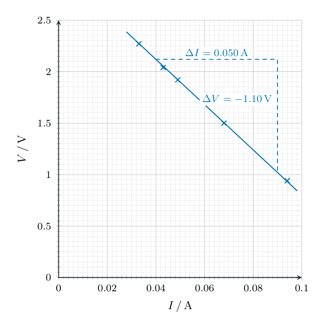
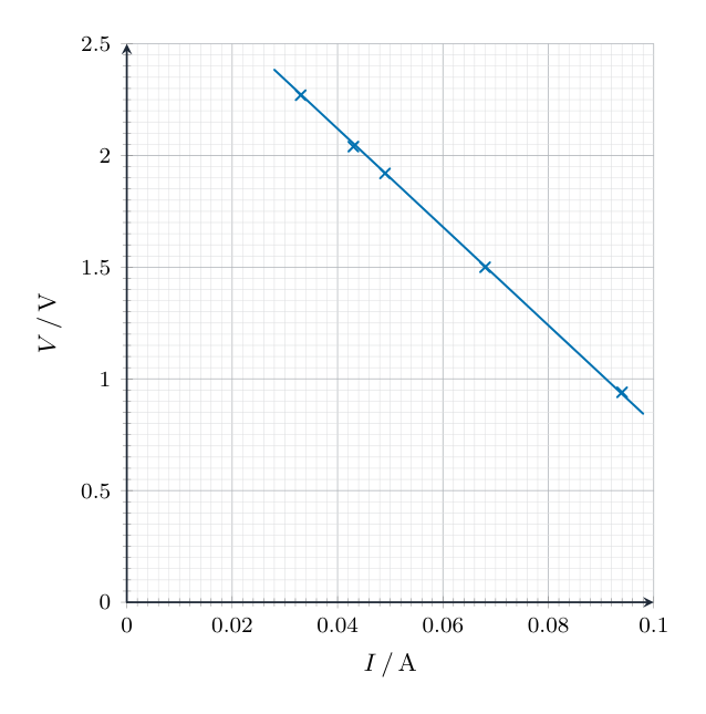
  • Plot $I$ horizontally and $V$ vertically, starting at zero. The example graph below uses the voltages from (b) and (c); use your own readings.
  • The example currents are $0.094$, $0.068$, $0.049$, $0.043$ and $0.033\,\mathrm{A}$. Draw a thin best-fit straight line.
Worked answer drawing

2(f)

  • Mark a large gradient triangle on the best-fit line, as shown for the example graph.
  • $G = \Delta V/\Delta I = (1.02-2.12)/(0.090-0.040) = \mathbf{-22}\,\mathrm{\Omega}$. Use values from your own line.
Worked answer drawing

2(g)

  • Use the size of the gradient: $R_Z = |G|$. For example, if $G = -22\,\mathrm{\Omega}$, then $R_Z = \mathbf{22}\,\mathrm{\Omega}$ to the nearest ohm.
Original question

Log in or create account

IGCSE, A-Level & AP