| 考生应能: | 注释与指导 |
|---|---|
| 1 识别并使用逻辑门的标准符号 | • 见第4节关于逻辑门符号的内容 |
| 2 定义并理解逻辑门的功能 | • 包括:– 非门(NOT)– 与门(AND)– 或门(OR)– 与非门(NAND)– 或非门(NOR)– 异或门(XOR / EOR)– 所有可能二进制输入所产生的二进制输出 • 非门是单输入门 • 所有其他门均限制为两个输入 |
| 3 (a) 使用逻辑门根据以下来源构建指定的逻辑电路:(i) 问题描述 (ii) 逻辑表达式 (iii) 真值表 (b) 根据以下来源完成真值表:(i) 问题描述 (ii) 逻辑表达式 (iii) 逻辑电路 | • 电路图必须严格按照给定语句绘制,不得化简 • 逻辑电路最多包含三个输入和一个输出 • 供完成的三输入真值表示例:A B C 输出 | 0 0 0 | 0 | 0 0 1 | 0 | 0 1 0 | 0 | 0 1 1 | 0 | 1 0 0 | 0 | 1 0 1 | 0 | 1 1 0 | 0 | 1 1 1 | 0 |
| (c) 根据以下来源写出逻辑表达式:(i) 问题描述 (ii) 逻辑电路 (iii) 真值表 |
布尔逻辑
IGCSE 计算机科学 · 知识点 10
 8:30
布尔逻辑
仔细看这个芯片。里面没有任何聪明之处。它不能思考。内部有数百万个微型开关,每个开关只能是两种状态之一…
英语旁白 · 英中内嵌字幕
教学大纲
来源:Cambridge International 教学大纲
10.1
什么是布尔逻辑?

English
Boolean logic 布尔逻辑 works with values that are either true or false. In electronics these are shown as 1 (true) and 0 (false). A logic gate 逻辑门 takes one or more of these inputs and gives one output, following a fixed rule.
A truth table 真值表 lists every possible set of inputs and the output for each. You build it by writing out all the input combinations.
词汇
训练
| English | 中文 | 拼音 |
|---|---|---|
| Boolean logic/ˈbuːlɪən ˈlɒdʒɪk/ | 布尔逻辑 | bù ěr luó jí |
| logic gate/ˈlɒdʒɪk ɡeɪt/ | 逻辑门 | luó jí mén |
| truth table/truːθ ˈteɪbl/ | 真值表 | zhēn zhí biǎo |
10.2
六种逻辑门
English
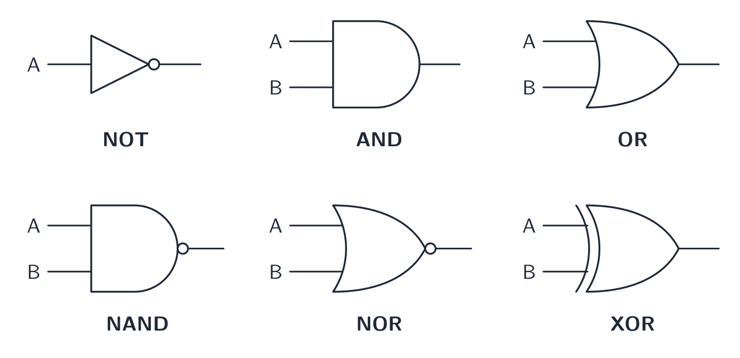
You must know six gates. NOT has one input; all the others have two inputs (A and B).

NOT gate
The NOT gate 非门 reverses the input. Output is 1 when the input is 0.
| A | Output |
|---|---|
| 0 | 1 |
| 1 | 0 |
AND gate
The AND gate 与门 gives output 1 only when both inputs are 1.

| A | B | Output |
|---|---|---|
| 0 | 0 | 0 |
| 0 | 1 | 0 |
| 1 | 0 | 0 |
| 1 | 1 | 1 |
OR gate
The OR gate 或门 gives output 1 when at least one input is 1.

| A | B | Output |
|---|---|---|
| 0 | 0 | 0 |
| 0 | 1 | 1 |
| 1 | 0 | 1 |
| 1 | 1 | 1 |
NAND gate
The NAND gate 与非门 is AND followed by NOT. The output is the opposite of AND.
| A | B | Output |
|---|---|---|
| 0 | 0 | 1 |
| 0 | 1 | 1 |
| 1 | 0 | 1 |
| 1 | 1 | 0 |
NOR gate
The NOR gate 或非门 is OR followed by NOT. The output is the opposite of OR.
| A | B | Output |
|---|---|---|
| 0 | 0 | 1 |
| 0 | 1 | 0 |
| 1 | 0 | 0 |
| 1 | 1 | 0 |
XOR gate
The XOR gate 异或门 (exclusive OR) gives output 1 when the inputs are different.
| A | B | Output |
|---|---|---|
| 0 | 0 | 0 |
| 0 | 1 | 1 |
| 1 | 0 | 1 |
| 1 | 1 | 0 |
探索
逻辑门
切换输入并选择门以查看输出——与门、或门、非门、与非门、或非门、异或门。
词汇
训练
| English | 中文 | 拼音 |
|---|---|---|
| NOT gate/nɒt ɡeɪt/ | 非门 | fēi mén |
| AND gate/ænd ɡeɪt/ | 与门 | yǔ mén |
| OR gate/ɔː ɡeɪt/ | 或门 | huò mén |
| NAND gate/nænd ɡeɪt/ | 与非门 | yǔ fēi mén |
| NOR gate/nɔː ɡeɪt/ | 或非门 | huò fēi mén |
| XOR gate/ˈeksɔː ɡeɪt/ | 异或门 | yì huò mén |
10.3
逻辑表达式
English
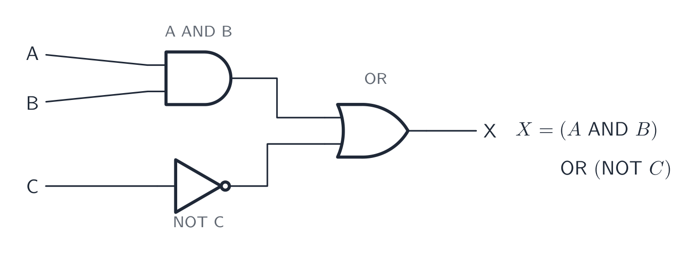
A logic expression 逻辑表达式 writes a circuit using letters and gate words. The usual way to write the gates:
| Gate | In words |
|---|---|
| NOT A | NOT A |
| A AND B | A AND B |
| A OR B | A OR B |
For example, the expression (A AND B) OR (NOT C) means: do A AND B, do NOT C, then OR the two results together.
探索
真值表
构建与门、或门、异或门和非门的真值表——每个表达式背后的逻辑。
词汇
训练
| English | 中文 | 拼音 |
|---|---|---|
| logic expression/ˈlɒdʒɪk ekˈspreʃn/ | 逻辑表达式 | luó jí biǎo dá shì |
10.4
逻辑电路
English
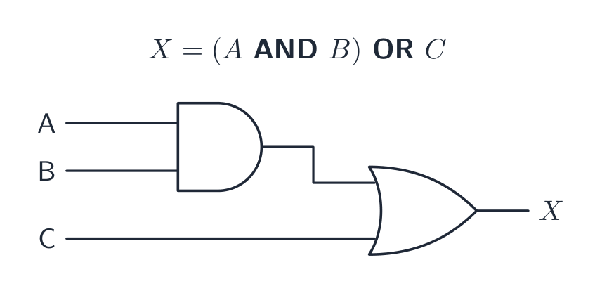
A logic circuit 逻辑电路 joins gates together to carry out a task. The output of one gate can become the input of another. At IGCSE a circuit has up to three inputs and one output.
You must be able to move between four forms:
- a problem statement 问题陈述 (a description in words),
- a logic expression,
- a logic circuit,
- a truth table.
From a problem statement to a circuit
Read the statement and pick out the conditions and the logic words (and, or, not). For example:
An alarm (X) sounds when the door is open (A) AND the system is switched on (B).
This is X = A AND B, so you draw one AND gate with inputs A and B.
Completing a truth table from a circuit or expression
To fill in a truth table:
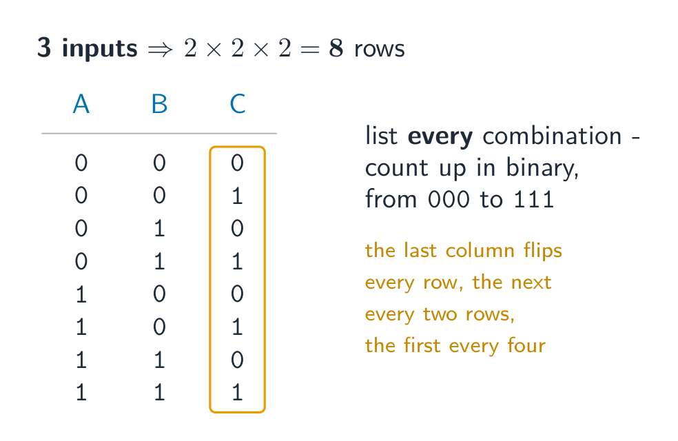
- Write all the input combinations. For three inputs there are 8 rows (000 up to 111).
- Work out each gate's output in order, one column at a time.
- The last column is the final output.
| A | B | C | A AND B | (A AND B) OR C |
|---|---|---|---|---|
| 0 | 0 | 0 | 0 | 0 |
| 0 | 0 | 1 | 0 | 1 |
| 0 | 1 | 0 | 0 | 0 |
| 0 | 1 | 1 | 0 | 1 |
| 1 | 0 | 0 | 0 | 0 |
| 1 | 0 | 1 | 0 | 1 |
| 1 | 1 | 0 | 1 | 1 |
| 1 | 1 | 1 | 1 | 1 |
Adding a middle "working" column for each gate makes the final output easy to fill in. Always draw the circuit exactly as the statement says, without simplifying it.
Worked example. Complete the truth table for X = (A AND B) OR (NOT C) for the row A = 1, B = 0, C = 0. Work outwards from the brackets, one gate at a time. First A AND B = 1 AND 0 = 0, because AND needs both inputs to be 1. Next NOT C = NOT 0 = 1. Finally OR the two results: 0 OR 1 = 1. So X = 1. Give each intermediate gate its own column rather than trying to do the whole expression in one step: with three inputs there are $2^3 = 8$ rows, and those intermediate columns are where the method marks live even if the final answer slips.
Worked example (all four forms). A greenhouse fan (X) switches on if the temperature is high (T) and the window is not open (W), or if the humidity is high (H).
Step 1: expression. “and the window is not open” is T AND NOT W; “or” joins H: X = (T AND NOT W) OR H.
Step 2: circuit. W goes through a NOT gate first; its output and T go into an AND gate; the AND output and H go into an OR gate.
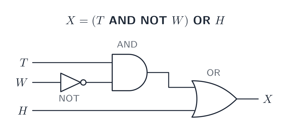
Step 3: truth table. Eight rows, with a working column for each gate:
| T | W | H | NOT W | T AND NOT W | X |
|---|---|---|---|---|---|
| 0 | 0 | 0 | 1 | 0 | 0 |
| 0 | 0 | 1 | 1 | 0 | 1 |
| 0 | 1 | 0 | 0 | 0 | 0 |
| 0 | 1 | 1 | 0 | 0 | 1 |
| 1 | 0 | 0 | 1 | 1 | 1 |
| 1 | 0 | 1 | 1 | 1 | 1 |
| 1 | 1 | 0 | 0 | 0 | 0 |
| 1 | 1 | 1 | 0 | 0 | 1 |
Step 4: check against the words. Whenever H = 1 the fan is on (rows 2, 4, 6, 8); otherwise it is on only for T = 1, W = 0 (row 5). Five rows give X = 1.
Going the other way, from a circuit to an expression, start at the inputs and write each gate's output on its wire, then join them at the last gate. Use brackets around each gate's result so the order is clear.
词汇
训练
| English | 中文 | 拼音 |
|---|---|---|
| logic circuit/ˈlɒdʒɪk ˈsɜːkɪt/ | 逻辑电路 | luó jí diàn lù |
| problem statement/ˈprɒbləm ˈsteɪtmənt/ | 问题陈述 | wèn tí chén shù |
10.5
考试技巧
English
- Learn all six gates and their truth tables: NOT, AND, OR, NAND (NOT AND), NOR (NOT OR), XOR (output 1 when the inputs are different).
- Build a truth table with all input rows (2 inputs → 4 rows, 3 inputs → 8), counting up in binary, and add a working column for each gate.
- Turn a problem statement into a logic expression by picking out the AND / OR / NOT words, then draw it exactly as written — do not simplify it.
- NAND and NOR give the opposite output to AND and OR; a small circle on a gate's output means the result is inverted.
该知识点的互动课程
逐步完成,配合即时检查练习。