各単位は物語で始まり、形式的な概念の前に図を示し、定義
用語を正確に定義し、数字が増加する2つの例題を解き進めます。
機械による検証で、古典的なミスを列挙し、3行の
summary. The checking habit: every phasor answer verifies in a second
極座標対直交座標、または時間領域対複素数のような表現において。
複素算術は単なる帳簿付けに過ぎず、検証がそれを正しく保ちます。
誠実さを担保します。
The mains voltage crosses zero a hundred times a second, yet a resistor there
一定の電力を消費します。なぜなら、振幅と位相が繰り返しの
パターンに収束するためです。正弦波$v(t) = V_{m}\cos(\omega t + \varphi)$はフェーザになります。
$V = V_{m}\angle\varphi$ — 振幅と位相、および周波数
が既知である。微分は $j\omega$ を乗算するため、単一周波数において
各要素には インピーダンス が与えられ、
$$Z_R = R \qquad Z_L = j\omega L \qquad Z_C = \frac{1}{j\omega C}$$
Summary: one frequency → phasors; $Z_R$ flat, $Z_L$ up 90°, $Z_C$ down 90°;
すべてのDC手法が適用され、各解答を別の表現で検証すること。
探索
Complex impedance sets the current phase
$\mathbf{I}=\mathbf{V}/Z$
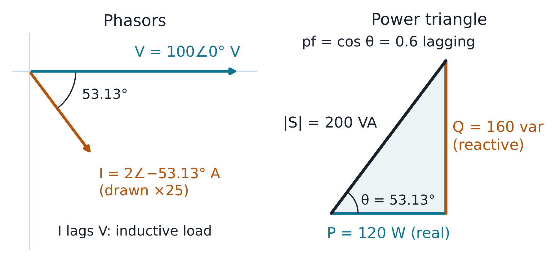
The 30 Ω resistor and +j40 Ω inductor give 50∠53.13° Ω in series, so a 100 V peak supply produces a 2 A peak current that lags by 53.13°. Compare the parallel example and a capacitive reactance, then connect each phasor to its instantaneous waveform.
** worked example 2 (三相モーター、拡大版 )**。バランスされたスター接続
モーターが415 V(線間)、50 Hzの電源に接続され、相インピーダンスが相あたり$10 + j10\ \Omega$である場合。
相電圧$= 415/\sqrt{3} = 239.6$ V;相電流
$= 239.6/\sqrt{10^{2} + 10^{2}} = 239.6/14.14 = 16.94$ A(ライン電流と等しい)
45 W — そして
$P = 3 \times 239.6 \times 16.94 \times \cos 45^{\circ} = 8611$ W — および
ライン公式 $\sqrt{3} \times 415 \times 16.94 \times 0.7071 = 8611$ W ✓ は
2つの経路が一致する。相単独計算でも欠損部分を導出:$Q = 3
\times 239.6 \times 16.94 \times \sin 45^{\circ} = 8611$ var、力率 pf 0.707
lagging, and (for a delta-connected motor of the same impedance) the phase
current would be $415/14.14 = 29.3$ A with line current $\sqrt{3} \times
29.3 = 50.8$ A — the star/delta factor is exactly the $\sqrt{3}$ bookkeeping.
At 100 V RMS, the 30 + j40 Ω load draws 2 A and uses 120 W plus 160 var. Compare no capacitor, exact correction and over-correction: supply current reaches a minimum at unity power factor, while load current and real power stay unchanged.
Release the 0.2 H and 0.05 F circuit from 1 V with zero current. Compare R = 2, 4 and 8 Ω on the same physical time axis, inspect the roots and energy, then change either initial condition to see why a second-order circuit needs both.
** worked example 1 (電圧増幅、確認済み)。$R = 5\ \Omega$,
$L = 0.1$ H, $C = 10\ \mu F$: $\omega_{0} = 1/\sqrt{0.1 \times 10^{-5}} =
1000$ rad/s; $Q = \omega_{0}L/R = 1000 \times 0.1/5 = 20$ 。源電圧が
10 V, the current at resonance is $10/5 = 2$ A, and $V_{L} = \omega_{0}LI =
200$ V — twenty times the source. Check: $V_{C} = I/(\omega_{0}C) =
2/0.01 = 200$ V ✓; どちらも 200 V で、位相は 180° ずれているため、和はゼロになる。
** worked example 2 (半電力帯域、拡大版)。同一回路の
帯域幅は $BW = \omega_{0}/Q = 1000/20 = 50$ rad/s であり、半電力周波数は
$\omega_{1} = 975.3$, $\omega_{2} = 1025.3$ rad/s に計算される —
their difference is 50.0 ✓ (machine-verified). They sit almost evenly either
side of 1000; exactly, $\omega_{1}\omega_{2} = \omega_{0}^{2}$ (symmetric on a
対称である)。
帯域端 $|Z| = \sqrt{2}R = 7.07\ \Omega$ において、電流は
最大値の $1/\sqrt{2}$ となり、各反応素子には源電圧の
$Q/\sqrt{2} \approx 14$ 倍の電源電圧 — まだ増幅であり、単に
past its peak. This is the selectivity a tuner sells: at 900 rad/s (a
neighbouring station two bandwidths away) the current is down to
$10/\sqrt{R^{2} + (\omega L - 1/\omega C)^{2}} = 10/|5 + j(90 - 111.1)| =
10/21.7 = 0.46$ A — under a quarter of the resonant 2 A.
よくある間違い。 増幅係数$Q$のみを報告し、他の要素を確認しない(両方の要素が一致している必要がある)。
element (both must match). Using $f_{0}$ where $\omega_{0}$ belongs (factor
$2\pi$). Believing resonance maximises power at any source impedance — it
minimises |Z|, which maximises current only for a stiff source.
A 10 V peak source drives the 5 Ω, 0.1 H and 10 µF circuit. At 1000 rad/s the current is 2 A and both reactive voltages are 200 V. Compare the half-power frequencies and the neighbouring 900 rad/s signal, then change resistance to connect Q with bandwidth.
** worked example 1(ローパス、端点確認済み)。ローパスRCに
$R = 1.6$ kΩ、$C = 0.1\ \mu F$: $\omega_{c} = 1/(1600 \times 10^{-7}) =
6250$ rad/s (995 Hz). At $\omega_{c}$ the gain is $1/\sqrt{2} = -3$ dB および
位相 −45°;$10\omega_{c}$ における直線近似は −20 dB を示す
(exact −20.04)。端点を確認する:低周波 $H = 1$ (0 dB) において、
$100\omega_{c}$ ≈ −40 dB — コーナーを越えた各デケードあたり 20 dB ずつ減衰する。これは
デシベル演算の$20\log_{10}10 = 20$である。
** worked example 2(ハイパスの鏡像、機械検証済み、拡張版)。**
出力を抵抗器に切り替えると、同じ
$\omega_{c} = 6250$ rad/s のハイパス回路が得られる:$H(j\omega) = (j\omega/\omega_{c})/(1 +
j\omega/\omega_{c})$. At $0.1\omega_{c}$: $-20.04$ dB at $+84.3^{\circ}$;
$\omega_{c}$ において:$-3.01$ dB at $+45^{\circ}$;$10\omega_{c}$ において:$-0.04$ dB at
$+5.7^{\circ}$(すべて機械検証済み)— ロウパスの完全な鏡像であり、
位相は 先行 し、ストップバンドは上方ではなく下方にある。設計の要点:
より急な 40 dB/decade の減衰には、2段の級聯が必要であり、(その
間の負荷影響を考慮すると)、級聯は利得を掛け合わせるため、dB値は
加算される——単位 4.7 のABCD行列と同じ連鎖論理である。
よくある間違い。 角周波数において −3 dB を「フィルタ内で損失する半分の電力」と読み取る(これは「ミッドバンドに対する負荷への出力電力の半分」である)。混同する
コーナー(これは負荷への 送られる電力の半分 vs 中央帯域 です)。混合する
$\omega$ と $f$ を同じ軸に配置する。位相を忘れる:振幅が平坦なフィルタでも、位相の傾きによってパルスを破壊することがある。
振幅は位相勾配によってパルスを壊す可能性があります。
Summary: poles −20 dB/decade above their corner, zeros +20; −3 dB and ±45° at
コーナー;アスペクトは設計ツールであり、正確な曲線は検証用です。
探索
The exact curve rounds the Bode corner
$H_{total}=H_{stage}^{N}$
The 1.6 kΩ and 0.1 µF section has a 6250 rad/s corner. Compare exact gain and phase with straight-line approximations, swap the output to make a high-pass, and see how two buffered stages multiply gain and shift the overall half-power corner.
Shunt Y = −j0.1 S followed by series Z = j10 Ω gives A = 1 and D = 2. Reverse the blocks and those entries swap. Compare the z parameters and open-circuit input impedance, then connect a load and follow the opposite signs of I₂ and load current.