Fig. 8.1 shows the single turn coil of a simple direct current (d.c.) motor.

Explain the direction of the turning effect as seen by an observer at O.[2]
The coil is replaced by an otherwise identical new coil with three turns and the same current in the coil.
State how the turning effect compares with the turning effect in (i).[1]
A third coil is identical to the coil in (i) except that its resistance is three times greater. The potential difference (p.d.) across the coil is the same as the p.d. in (i).
State how the turning effect compares with the turning effect in (i).[1]
Fig. 8.2 is a voltage–time graph showing the output of a simple alternating current (a.c.) generator at times $t_{0}$, $t_{1}$, $t_{2}$ and $t_{3}$.

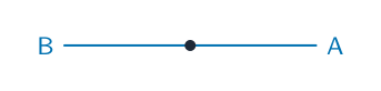
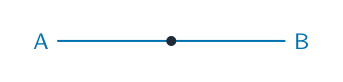
Fig. 8.3 is an end view of the plane of the coil of the generator at time $t_{0}$. The coil is rotating clockwise.

Draw an end view of the position of the plane of the coil at time $t_{1}$. Include the labels A and B.[1]
Draw an end view of the position of the plane of the coil at time $t_{2}$. Include the labels A and B.[1]
Draw an end view of the position of the plane of the coil at time $t_{3}$. Include the labels A and B.[1]
[Total: 7]