A student investigates circuits containing different combinations of resistors.
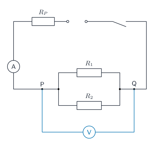
Circuit A is shown in Fig. 3.1. Circuit A is not complete.

On Fig. 3.1, complete the circuit to show a voltmeter connected to measure the potential difference (p.d.) across the terminals P and Q.[1]
The student measures the potential difference $V$ across the parallel combination of resistors $R_1$ and $R_2$ and measures the current $I$ in the circuit.
His readings are shown in Fig. 3.2 and Fig. 3.3.


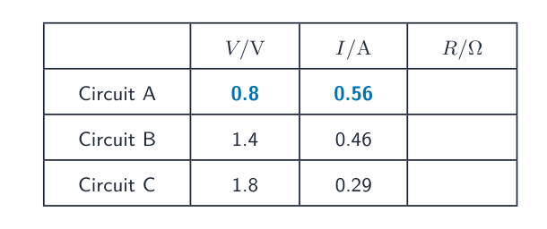
Read, and record in the first line of Table 3.1, the values of $V$ and $I$ shown on the meters in Fig. 3.2 and Fig. 3.3.[2]
Table 3.1
| $V$ / V | $I$ / A | $R$ / $\Omega$ | |
| circuit A | |||
| circuit B | 1.4 | 0.46 | |
| circuit C | 1.8 | 0.29 |
The student rearranges the resistors between terminals P and Q, as shown in Fig. 3.4, to form circuit B and circuit C. The new values of $V$ and $I$ are shown in Table 3.1.

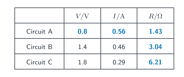
For each circuit, calculate and record in Table 3.1 a resistance $R$. Use the values of $V$ and $I$ in Table 3.1 and the equation:
[1]
Calculate resistance $R_A$. Use the value of $R$ from circuit A and the equation:
$R_A =$ $\Omega$
Record resistance $R_B$. $R_B$ is equal to the value of $R$ from circuit B.
$R_B =$ $\Omega$
Calculate resistance $R_C$. Use the value of $R$ from circuit C and the equation:
$R_C =$ $\Omega$[2]
A student suggests that $R_A$, $R_B$ and $R_C$ should all be equal.
State whether your results support this suggestion. Justify your statement with reference to values from your results.
statement
justification [2]
The circuits use a 3 V power supply.
Briefly explain why resistor $R_P$, shown in Fig. 3.1, must remain in place throughout the experiment.
$R_P$ has a resistance of $4.0\,\Omega$. Use Fig. 3.3 and the values in Table 3.1 to support your answer.[1]
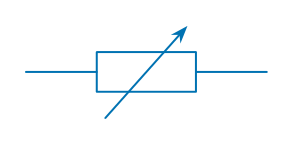
A student determines the resistance of $R_1$. He uses a variable resistor in circuit B to control the current and draws a graph of $V$ against $I$.
Draw the circuit symbol for a variable resistor.[1]
Briefly explain one advantage of using a variable resistor to control the current.[1]
[Total: 11]