A student investigates the refraction of light by a transparent block.
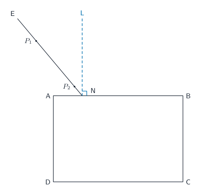
The student’s ray-trace sheet is shown full-size in Fig. 3.1.

The student places a transparent block ABCD near the centre of the ray-trace sheet as indicated in Fig. 3.1.
Draw a normal to point N, extending above AB. Label the upper end of the normal with the letter L.[1]
The student draws line EN as shown in Fig. 3.1.
On Fig. 3.1, measure the acute angle $\theta$ between the lines LN and EN.
An acute angle is an angle of less than 90°.
$\theta$ = [1]
The student places two pins $P_1$ and $P_2$ on line EN as shown in Fig. 3.1.
Measure distance $d$ between pins $P_1$ and $P_2$.
$d$ = cm[1]
State whether the two pins are a suitable distance apart for accurate ray tracing.
Explain your answer.
statement
explanation [1]
The student views the images of $P_1$ and $P_2$ through the block.
He places two pins $P_3$ and $P_4$ so that pins $P_3$ and $P_4$ and the images of $P_1$ and $P_2$ all appear exactly one behind the other.
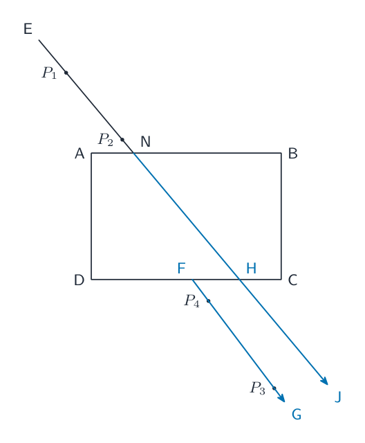
Draw a line through $P_3$ and $P_4$. Extend this line to meet CD.
Label the point at which this line meets CD with the letter F. Label the lower end of this line with the letter G.
Extend line EN to approximately 5 cm below line CD.
Label the point at which this line crosses CD with the letter H. Label the lower end of this line with the letter J.[1]
Measure the acute angle $\alpha$ between lines CD and GF.
$\alpha$ = °
Measure the acute angle $\beta$ between lines CD and JH.
$\beta$ = °[1]
A student suggests that angle $\alpha$ should be equal to angle $\beta$.
State whether your results support this suggestion. Justify your answer by reference to values from your results.
statement
justification [2]
Describe two techniques to use in this type of experiment to ensure results are accurate.
1
2
[2]
Suggest one reason why different students, all doing this experiment carefully, may not obtain identical results.
[1]
[Total: 11]