Skip to content

Electric Circuits

AP Physics C: Electricity and Magnetism · Topic 11

Train
11.1

Electric Current

Syllabus
Learning ObjectiveEssential Knowledge

11.1.A
Describe the movement of electric charges through a medium.

  • 11.1.A.1 Current is the rate at which charge passes through a cross-sectional area of a wire.
    • Equation: $I = \dfrac{dq}{dt}$
    • 11.1.A.1.i Current within a conductor consists of charge carriers traveling through the conductor with an average drift velocity.
      • Equation: $I = nqv_d A$
    • 11.1.A.1.ii Electric charge moves in a circuit in response to an electric potential difference, sometimes referred to as electromotive force, or $\mathrm{emf}$ ($\mathcal{E}$).
    • 11.1.A.1.iii If the current is zero in a section of wire, the net motion of charge carriers in the wire is also zero, although individual charge carriers will not have zero speed.
  • 11.1.A.2 Current density is the flow of charge per unit area.
    • Equation: $I = \int \vec{J} \cdot d\vec{A}$
    • 11.1.A.2.i Current density is related to the motion of the charge carriers within a conductor.
      • Equation: $\vec{J} = nq\vec{v}_d$
    • 11.1.A.2.ii Current density is a vector quantity.
    • 11.1.A.2.iii A potential difference across a conductor creates an electric field within the conductor that is proportional to the resistivity of the conductor and the current density.
      • Equation: $\vec{E} = \rho\vec{J}$
  • 11.1.A.3 If a function of current density is given, the total current can be determined by integrating the current density over the area.
    • Equation: $I_{\text{tot}} = \int \vec{J}(r) \cdot d\vec{A}$
  • 11.1.A.4 Although current is a scalar quantity, it does have a direction. Because its direction is relative to the current carrier and not space, current does not obey the laws of vector addition and has no vector components.
    • 11.1.A.4.i The direction of conventional current is chosen to be the direction in which positive charge would move.
    • 11.1.A.4.ii In common circuits, the current is actually due to the movement of electrons (negative charge carriers).

Source: College Board AP Course and Exam Description

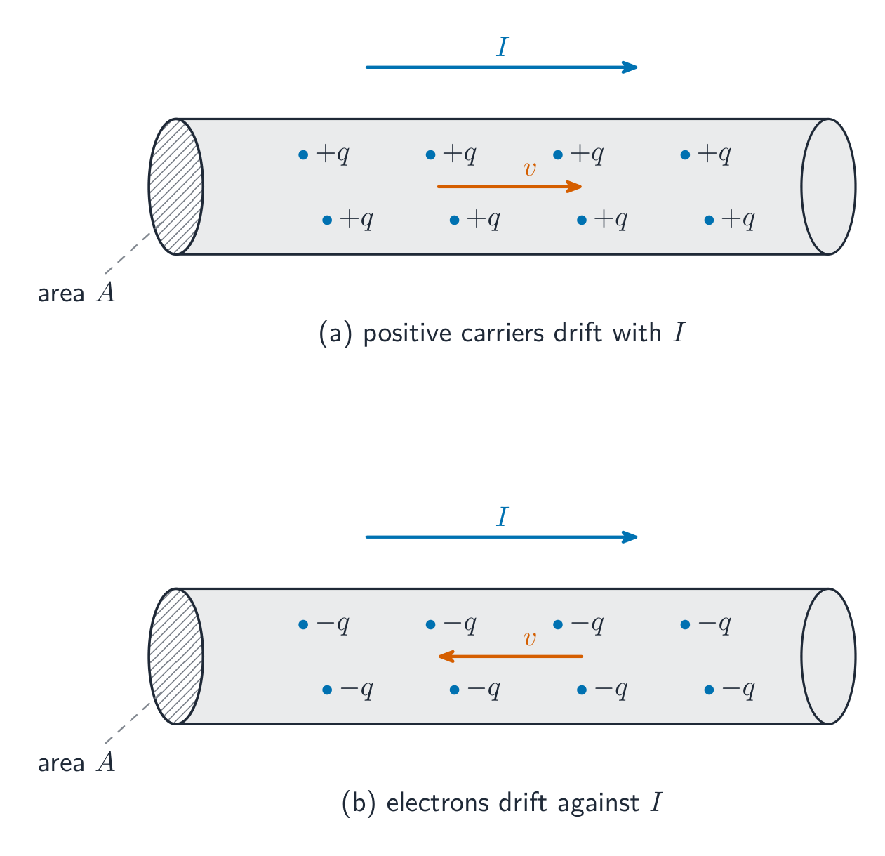
Electric current 电流 is the rate at which charge passes a cross-section of wire, $I=\dfrac{dq}{dt}$, measured in amperes 安培. Conventional current points the way positive charge would move. Microscopically, a current is a slow drift of many carriers:

$$I=nqv_dA,$$

with $n$ the number of carriers per volume, $q$ the charge each carries, $v_d$ the drift velocity 漂移速度, and $A$ the cross-sectional area 横截面积.

Charge carriers drift slowly through a conductor to make a current Charge carriers drift slowly through a conductor to make a current

Worked example. A copper wire with $A=1.0\times10^{-6}\ \text{m}^2$ and $n=8.5\times10^{28}\ \text{m}^{-3}$ carries $1.7\ \text{A}$. Then $v_d=\dfrac{I}{nqA}=\dfrac{1.7}{(8.5\times10^{28})(1.6\times10^{-19})(1.0\times10^{-6})}\approx1.3\times10^{-4}\ \text{m/s}$ – the carriers drift slower than a snail, even though the signal travels near light speed.

Current density 电流密度 is charge flow per unit area, $\vec{J}=nq\vec{v}_d$, linked to the field driving it by $\vec{E}=\rho\vec{J}$. In general $I=\int\vec{J}\cdot d\vec{A}$; if $J(r)$ varies across the wire, integrate it over the cross-section to get the total current. One care point: current has a direction along its wire, but it is a scalar 标量 – currents do not add as vectors, and there are no "components of current".
Vocabulary Train
English Chinese Pinyin
Electric current 电流 diàn liú
amperes 安培 ān péi
drift velocity 漂移速度 piāo yí sù dù
cross-sectional area 横截面积 héng jié miàn jī
Current density 电流密度 diàn liú mì dù
scalar 标量 biāo liàng
11.2

Electric Circuits

Syllabus
Learning ObjectiveEssential Knowledge

11.2.A
Describe the behavior of a circuit.

  • 11.2.A.1 A circuit is composed of electrical loops, which can include wires, batteries, resistors, lightbulbs, capacitors, inductors, switches, ammeters, and voltmeters.
  • 11.2.A.2 A closed electrical loop is a closed path through which charges may flow.
    • 11.2.A.2.i A closed circuit is one in which charges would be able to flow.
    • 11.2.A.2.ii An open circuit is one in which charges would not be able to flow.
    • 11.2.A.2.iii A short circuit is one in which charges would be able to flow with no change in potential difference.
  • 11.2.A.3 A single circuit element may be part of multiple electrical loops.
  • 11.2.A.4 Circuit schematics are representations used to describe and analyze electric circuits.
    • 11.2.A.4.i The properties of an electric circuit are dependent on the physical arrangement of its constituent elements.
    • 11.2.A.4.ii Circuit elements have common symbols that are used to create schematic diagrams. Variable elements are indicated by a diagonal strikethrough arrow across the standard symbol for that element. (Symbols: Battery, Bulb, Switch, Capacitor, Resistor, Ammeter, Voltmeter, Inductor.)

Boundary statement: Unless otherwise specified, all circuit schematic diagrams will be drawn using conventional current.

Source: College Board AP Course and Exam Description

A circuit is a set of closed loops built from wires, batteries, resistors, lightbulbs, capacitors, inductors, switches, and meters; charge can flow only around a closed path. One element can belong to several loops at once – that is what makes multi-loop problems interesting. Every analysis starts by reading the circuit diagram 电路图: trace each loop and identify which elements share the same current (series 串联) and which share the same potential difference (parallel 并联).

Explore

Build series and parallel circuits

In series the same current flows through every bulb and voltage divides; in parallel each branch gets the full voltage. Switch mode to see the bulbs' brightness change.

Vocabulary Train
English Chinese Pinyin
circuit diagram 电路图 diàn lù tú
series 串联 chuàn lián
parallel 并联 bìng lián
11.3

Resistance, Resistivity, and Ohm's Law
Syllabus
Learning ObjectiveEssential Knowledge

11.3.A
Describe the resistance of an object using physical properties of that object.

  • 11.3.A.1 Resistance is a measure of the degree to which an object opposes the movement of electric charge.
  • 11.3.A.2 The resistance of a resistor with uniform geometry is proportional to its resistivity and length and is inversely proportional to its cross-sectional area.
    • Equation: $R = \dfrac{\rho\ell}{A}$
    • 11.3.A.2.i Resistivity is a fundamental property of a material that depends on its atomic and molecular structure and quantifies how strongly the material opposes the motion of electric charge.
    • 11.3.A.2.ii The resistivity of a conductor typically increases with temperature.
    • 11.3.A.2.iii The total resistance of a resistor with uniform geometry, but that is made of a material whose resistivity varies along the length of the resistor, is given by $R = \int \dfrac{\rho(\ell)\,d\ell}{A}$.

11.3.B
Describe the electrical characteristics of elements of a circuit.

  • 11.3.B.1 Ohm's law relates current, resistance, and potential difference across a conductive element of a circuit.
    • Equation: $I = \dfrac{\Delta V}{R}$
    • 11.3.B.1.i Materials that obey Ohm's law have constant resistance for all currents and are called ohmic materials.
    • 11.3.B.1.ii The resistivity of an ohmic material is constant regardless of temperature.
    • 11.3.B.1.iii Resistors can also convert electrical energy to thermal energy, which may change the temperature of both the resistor and the resistor's environment.
    • 11.3.B.1.iv The resistance of an ohmic circuit element can be determined from the slope of a graph of the current in the element as a function of the potential difference across the element.

Source: College Board AP Course and Exam Description

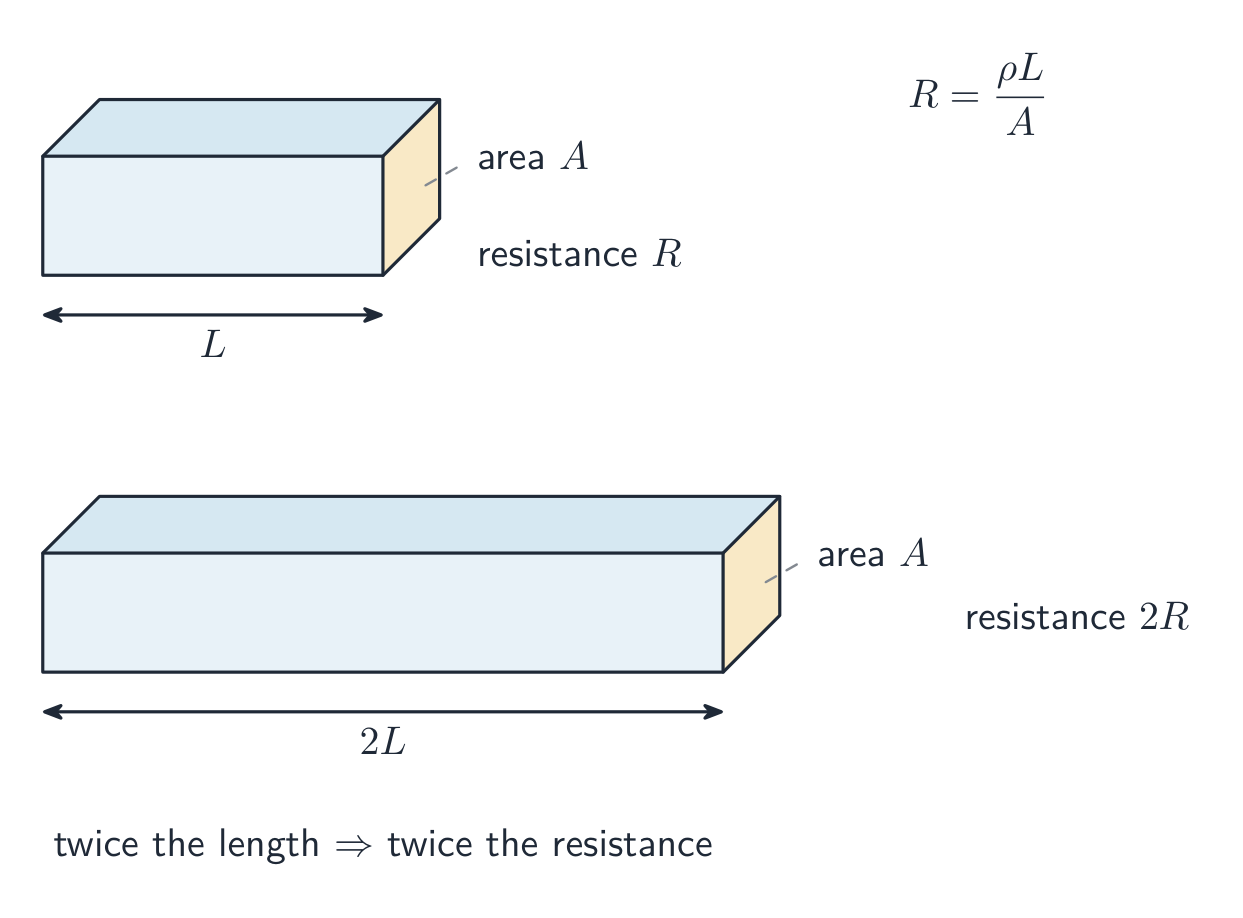
Resistance 电阻 measures how strongly an object opposes charge flow. It grows with the material's resistivity 电阻率 and the conductor's length, and shrinks with its area:

$$R=\frac{\rho\,\ell}{A}.$$

Ohm's law 欧姆定律 relates the current through an element to the potential difference across it:

$$I=\frac{\Delta V}{R}.$$

A longer conductor has more resistance; a wider one has less A longer conductor has more resistance; a wider one has less

Worked example. Stretch a wire to double its length: the volume is fixed, so the area halves, and $R=\rho\ell/A$ becomes $\rho(2\ell)/(A/2)=4R$ – four times the resistance. An element is ohmic 欧姆性 if $R$ stays constant (a straight line through the origin on an $I$$\Delta V$ graph); a lightbulb filament, which heats up, is not.

Explore

Apply Ohm's law

Ohm's law $V=IR$: for a fixed resistance, current is proportional to voltage. Raise the resistance and the same voltage pushes less current.

Vocabulary Train
English Chinese Pinyin
Resistance 电阻 diàn zǔ
resistivity 电阻率 diàn zǔ lǜ
Ohm's law 欧姆定律 ōu mǔ dìng lǜ
ohmic 欧姆性 ōu mǔ xìng
11.4

Electric Power

Syllabus
Learning ObjectiveEssential Knowledge

11.4.A
Describe the transfer of energy into, out of, or within an electric circuit, in terms of power.

  • 11.4.A.1 The rate at which energy is transferred, converted, or dissipated by a circuit element depends on the current in the element and the electric potential difference across it.
    • Equation: $P = I\Delta V$
    • Equation: $P = I^2 R = \dfrac{\Delta V^2}{R}$
  • 11.4.A.2 The brightness of a lightbulb increases with power, so power can be used to qualitatively predict the brightness of lightbulbs in a circuit.

Boundary statement: AP Physics C: Electricity & Magnetism only expects students to analyze the transfer of mechanical and electrical energy, although students should be aware that electrical energy can also be dissipated in the form of thermal energy.

Source: College Board AP Course and Exam Description

A charge $q$ falling through a potential difference $\Delta V$ gives up energy $q\Delta V$, so the rate of energy transfer in an element is

$$P=I\,\Delta V=I^2R=\frac{(\Delta V)^2}{R}.$$

In a resistor all of it becomes heat. Use the form whose quantities you actually know – and use power to rank lightbulb brightness: brighter = more power, not necessarily more resistance. In series, the larger resistance is brighter ($P=I^2R$, same $I$); in parallel, the smaller one is ($P=\Delta V^2/R$, same $\Delta V$).

Explore

Read an I-V characteristic

Power is $P=IV$. A resistor's I-V line is straight, but a lamp curves as it heats and its resistance rises. The area under I-V relates to the energy delivered.

11.5

Compound Direct Current Circuits
Syllabus
Learning ObjectiveEssential Knowledge

11.5.A
Describe the equivalent resistance of multiple resistors connected in a circuit.

  • 11.5.A.1 Circuit elements may be connected in series and/or in parallel.
    • 11.5.A.1.i A series connection is one in which any charge passing through one circuit element must proceed through all elements in that connection and has no other path available. The current in each element in series must be the same.
    • 11.5.A.1.ii A parallel connection is one in which charges may pass through one of two or more paths. Across each path, the potential difference is the same.
  • 11.5.A.2 A collection of resistors in a circuit may be analyzed as though it were a single resistor with an equivalent resistance $R_{\text{eq}}$.
    • 11.5.A.2.i The equivalent resistance of a set of resistors in series is the sum of the individual resistances.
      • Equation: $R_{\text{eq},s} = \sum_{i} R_i$
    • 11.5.A.2.ii The inverse of the equivalent resistance of a set of resistors connected in parallel is equal to the sum of the inverses of the individual resistances.
      • Equation: $\dfrac{1}{R_{\text{eq},p}} = \sum_{i} \dfrac{1}{R_i}$
    • 11.5.A.2.iii When resistors are connected in parallel, the number of paths available to charges increases, and the equivalent resistance of the group of resistors decreases.

11.5.B
Describe a circuit with resistive wires and a battery with internal resistance.

  • 11.5.B.1 Ideal batteries have negligible internal resistance. Ideal wires have negligible resistance.
    • 11.5.B.1.i The resistance of wires that are good conductors may normally be neglected, because their resistance is much smaller than that of other elements of a circuit.
    • 11.5.B.1.ii The resistance of wires may only be neglected if the circuit contains other elements that do have resistance.
    • 11.5.B.1.iii The potential difference a battery would supply if it were ideal is the potential difference measured across the terminals when there is no current in the battery and is sometimes referred to as its $\mathrm{emf}$ ($\mathcal{E}$).
  • 11.5.B.2 The internal resistance of a nonideal battery may be treated as the resistance of a resistor in series with an ideal battery and the remainder of the circuit.
  • 11.5.B.3 When there is current in a nonideal battery with internal resistance $r$, the potential difference across the terminals of the battery is reduced relative to the potential difference when there is no current in the battery.
    • Equation: $\Delta V_{\text{terminal}} = \mathcal{E} - Ir$

11.5.C
Describe the measurement of current and potential difference in a circuit.

  • 11.5.C.1 Ammeters are used to measure current at a specific point in a circuit.
    • 11.5.C.1.i Ammeters must be connected in series with the element in which current is being measured.
    • 11.5.C.1.ii Ideal ammeters have zero resistance so that they do not affect the current in the element that they are in series with.
  • 11.5.C.2 Voltmeters are used to measure electric potential difference between two points in a circuit.
    • 11.5.C.2.i Voltmeters must be connected in parallel with the element across which potential difference is being measured.
    • 11.5.C.2.ii Ideal voltmeters have infinite resistance so that no charge flows through them.
  • 11.5.C.3 Nonideal ammeters and voltmeters will change the properties of the circuit being measured.

Boundary statement: Unless otherwise stated, all batteries, wires, and meters are assumed to be ideal. Circuits with batteries of different potential differences connected in parallel will not be assessed.

Source: College Board AP Course and Exam Description

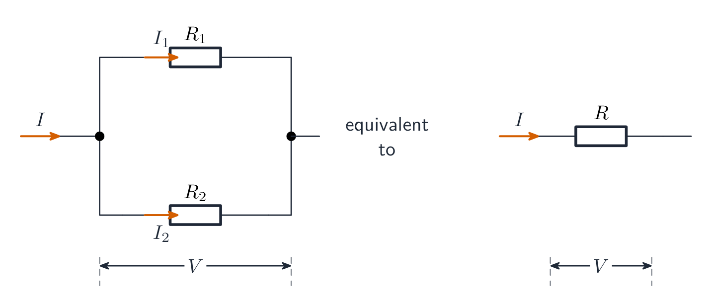
Reduce resistor networks to an equivalent resistance 等效电阻: series resistances add ($R_{\text{eq}}=R_1+R_2+\cdots$), while parallel resistances add as reciprocals ($\tfrac{1}{R_{\text{eq}}}=\tfrac{1}{R_1}+\tfrac{1}{R_2}+\cdots$ – always less than the smallest branch). Collapse the network step by step to find the battery current, then expand back out to find each element's current and voltage.

Worked example. A $12\ \text{V}$ battery drives a $4.0\ \Omega$ and a $2.0\ \Omega$ resistor in series: $R_{\text{eq}}=6.0\ \Omega$, $I=2.0\ \text{A}$, the voltages split $8.0\ \text{V}$ and $4.0\ \text{V}$, and the $4.0\ \Omega$ resistor dissipates $P=I^2R=16\ \text{W}$.

Resistors in parallel combine to a smaller equivalent resistance Resistors in parallel combine to a smaller equivalent resistance

Real batteries are not ideal. Model a battery as an ideal battery 理想电池 of emf $\varepsilon$ in series with its own internal resistance 内阻 $r$. When current flows, some emf is used up inside, so the terminal voltage 端电压 – what a voltmeter across the battery actually reads – drops:

$$\Delta V_{\text{terminal}}=\varepsilon-Ir.$$

Worked example. A battery with $\varepsilon=12\ \text{V}$ and $r=0.50\ \Omega$ supplies $2.0\ \text{A}$: the terminals sit at $\Delta V=12-2.0(0.50)=11\ \text{V}$. With no current, a voltmeter reads the full $12\ \text{V}$.

Meters: an ammeter 电流表 goes in series at the point whose current you want (ideal ammeter: zero resistance); a voltmeter 电压表 goes in parallel across the element (ideal voltmeter: infinite resistance). Non-ideal meters disturb the circuit they measure – a real ammeter adds series resistance, a real voltmeter steals current.

Vocabulary Train
English Chinese Pinyin
equivalent resistance 等效电阻 děng xiào diàn zǔ
ideal battery 理想电池 lǐ xiǎng diàn chí
internal resistance 内阻 nèi zǔ
terminal voltage 端电压 duān diàn yā
ammeter 电流表 diàn liú biǎo
voltmeter 电压表 diàn yā biǎo
11.6

Kirchhoff's Loop Rule

Syllabus
Learning ObjectiveEssential Knowledge

11.6.A
Describe a circuit or elements of a circuit by applying Kirchhoff's loop rule.

  • 11.6.A.1 Energy changes in simple electrical circuits may be represented in terms of charges moving through electric potential differences within circuit elements.
    • Equation: $\Delta U_E = q\Delta V$
  • 11.6.A.2 Kirchhoff's loop rule is a consequence of the conservation of energy.
    • 11.6.A.2.i Kirchhoff's loop rule states that the sum of potential differences across all circuit elements in a single closed loop must equal zero.
      • Equation: $\sum \Delta V = 0$
    • 11.6.A.2.ii The values of electric potential at points in a circuit can be represented by a graph of electric potential as a function of position within a loop.

Source: College Board AP Course and Exam Description

Charges moving through potential differences exchange energy ($\Delta U_E=q\Delta V$), and energy must balance around any closed path. That is Kirchhoff's loop rule 基尔霍夫回路定则:

$$\sum\Delta V=0\ \text{around any closed loop}.$$

Sign discipline wins these problems: crossing a battery from $-$ to $+$ is $+\varepsilon$; crossing a resistor with the assumed current is $-IR$ (against it, $+IR$). Write one equation per independent loop.

Vocabulary Train
English Chinese Pinyin
Kirchhoff's loop rule 基尔霍夫回路定则 jī ěr huò fū huí lù dìng zé
11.7

Kirchhoff's Junction Rule

Syllabus
Learning ObjectiveEssential Knowledge

11.7.A
Describe a circuit or elements of a circuit by applying Kirchhoff's junction rule.

  • 11.7.A.1 Kirchhoff's junction rule is a consequence of the conservation of electric charge.
  • 11.7.A.2 Kirchhoff's junction rule states that the total amount of charge entering a junction per unit time must equal the total amount of charge exiting that junction per unit time.
    • Equation: $\sum I_{\text{in}} = \sum I_{\text{out}}$

Source: College Board AP Course and Exam Description

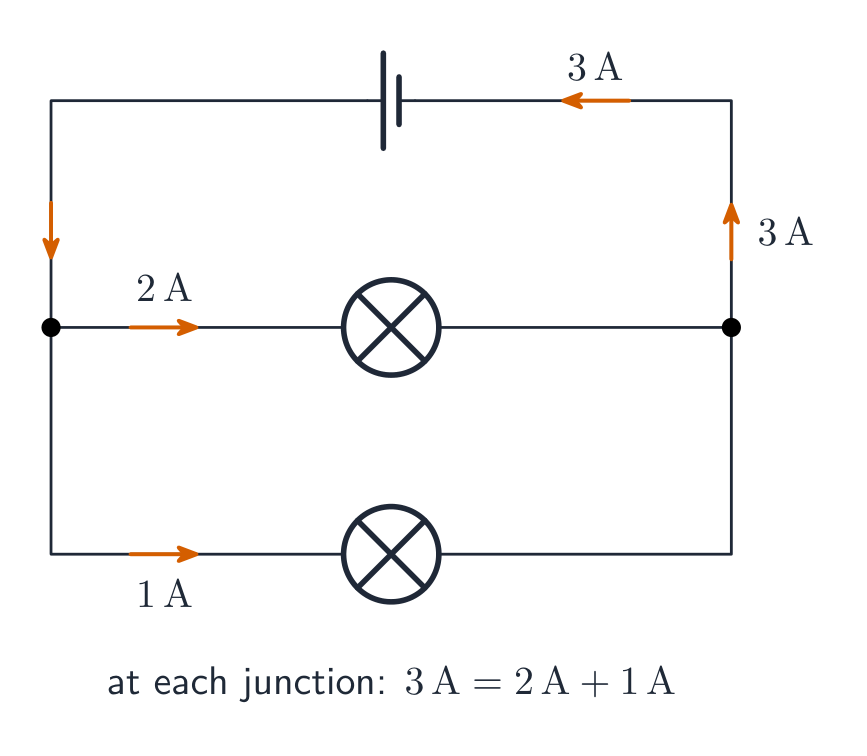
Kirchhoff's junction rule 基尔霍夫节点定则 is conservation of charge at a junction 节点:

$$\sum I_{\text{in}}=\sum I_{\text{out}}.$$

Current divides at a junction: what flows in equals what flows out Current divides at a junction: what flows in equals what flows out

Together the two rules solve any multi-loop circuit: assign a current to each branch, write junction equations, then loop equations, and solve. A negative answer just means that current flows opposite to your assumed direction.
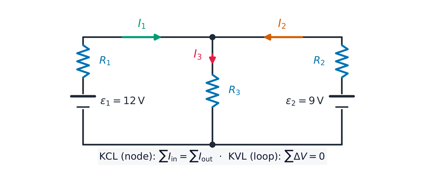
Two loop equations and one junction equation solve this two-battery circuit Two loop equations and one junction equation solve this two-battery circuit

Worked example. In the circuit above, $\varepsilon_1=12\ \text{V}$ with $R_1=1.0\ \Omega$ on the left, $\varepsilon_2=9.0\ \text{V}$ with $R_2=1.0\ \Omega$ on the right, and a shared middle resistor $R_3=2.0\ \Omega$ carrying $I_3=I_1+I_2$ (junction rule). The two loop equations are

$$12=I_1+2(I_1+I_2)=3I_1+2I_2,\qquad 9=I_2+2(I_1+I_2)=2I_1+3I_2.$$

Solving: $I_1=3.6\ \text{A}$, $I_2=0.60\ \text{A}$, so $I_3=4.2\ \text{A}$ through the middle. Check with the second loop: $2(3.6)+3(0.60)=9.0$ ✓.

Vocabulary Train
English Chinese Pinyin
Kirchhoff's junction rule 基尔霍夫节点定则 jī ěr huò fū jié diǎn dìng zé
junction 节点 jié diǎn
11.8

Resistor-Capacitor (RC) Circuits

Syllabus
Learning ObjectiveEssential Knowledge

11.8.A
Describe the equivalent capacitance of multiple capacitors.

  • 11.8.A.1 A collection of capacitors in a circuit may be analyzed as though it was a single capacitor with an equivalent capacitance $C_{\text{eq}}$.
    • 11.8.A.1.i The inverse of the equivalent capacitance of a set of capacitors connected in series is equal to the sum of the inverses of the individual capacitances.
      • Equation: $\dfrac{1}{C_{\text{eq},s}} = \sum_{i} \dfrac{1}{C_i}$
    • 11.8.A.1.ii The equivalent capacitance of a set of capacitors in series is less than the capacitance of the smallest capacitor.
    • 11.8.A.1.iii The equivalent capacitance of a set of capacitors in parallel is the sum of the individual capacitances.
      • Equation: $C_{\text{eq},p} = \sum_{i} C_i$
  • 11.8.A.2 As a result of conservation of charge, each of the capacitors in series must have the same magnitude of charge on each plate.

11.8.B
Describe the behavior of a circuit containing combinations of resistors and capacitors.

  • 11.8.B.1 The charge on a capacitor or the current in a resistor in an RC circuit can be described by a fundamental differential equation derived from Kirchhoff's loop rule.
    • Equation: $\mathcal{E} = \dfrac{dq}{dt}R + \dfrac{q}{C}$
  • 11.8.B.2 The time constant ($\tau$) is a significant feature of an RC circuit.
    • 11.8.B.2.i The time constant of an RC circuit is a measure of how quickly the capacitor will charge or discharge and is defined as $\tau = R_{\text{eq}}C_{\text{eq}}$.
    • 11.8.B.2.ii For a charging capacitor, the time constant represents the time required for the capacitor's charge to increase from zero to approximately 63 percent of its final asymptotic value.
    • 11.8.B.2.iii For a discharging capacitor, the time constant represents the time required for the capacitor's charge to decrease from fully charged to approximately 37 percent of its initial value.
  • 11.8.B.3 The potential difference across a capacitor and the current in the branch of the circuit containing the capacitor each change over time as the capacitor charges and discharges, but both will reach a steady state after a long time interval.
    • 11.8.B.3.i Immediately after being placed in a circuit, an uncharged capacitor acts like a wire, and charge can easily flow to or from the plates of the capacitor.
    • 11.8.B.3.ii As a capacitor charges, changes to the potential difference across the capacitor affect the charge on the plates of the capacitor, the current in the circuit branch in which the capacitor is located, and the electric potential energy stored in the capacitor.
    • 11.8.B.3.iii The potential difference across a capacitor, the current in the circuit branch in which the capacitor is located, and the electric potential energy stored in the capacitor all change with respect to time and asymptotically approach steady state conditions.
    • 11.8.B.3.iv After a long time, a charging capacitor approaches a state of being fully charged, reaching a maximum potential difference at which there is zero current in the circuit branch in which the capacitor is located.
    • 11.8.B.3.v Immediately after a charged capacitor begins discharging, the amount of charge on the capacitor and the energy stored in the capacitor begin to decrease.
    • 11.8.B.3.vi As a capacitor discharges, the amount of charge on the capacitor, the potential difference across the capacitor, and the current in the circuit branch in which the capacitor is located all decrease until a steady state is reached.
    • 11.8.B.3.vii After either charging or discharging for times much greater than the time constant, the capacitor and the relevant circuit branch may be modeled using steady-state conditions.

Source: College Board AP Course and Exam Description

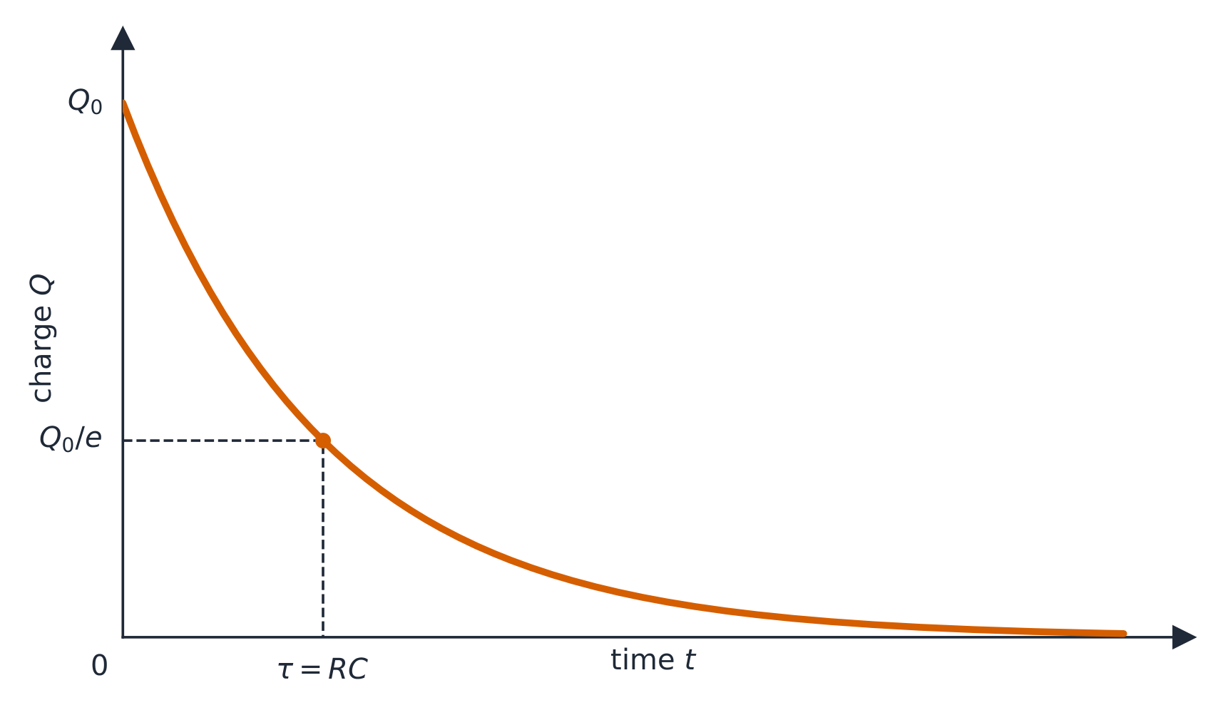
Discharging a capacitor: τ = RC
Charging a capacitor (RC)

Capacitor networks reduce like resistors but with the rules swapped: parallel capacitances add ($C_{\text{eq}}=C_1+C_2$), series add as reciprocals – and capacitors in series must carry the same charge on each plate, by conservation of charge. Use the equivalent capacitance 等效电容 to analyse the network, then expand back.

In an RC circuit RC电路, Kirchhoff's loop rule gives the differential equation

$$\varepsilon=R\frac{dq}{dt}+\frac{q}{C},$$

whose solutions are exponentials with time constant 时间常数 $\tau=RC$:

$$q(t)=Q\big(1-e^{-t/RC}\big)\ \text{(charging)},\qquad q(t)=Q\,e^{-t/RC}\ \text{(discharging)},\qquad i(t)=\frac{\varepsilon}{R}e^{-t/RC}.$$

The current is largest at the first instant and decays – it never "waits" for the capacitor. Learn the two limits: at $t=0$ an uncharged capacitor acts like a plain wire (maximum current); after a long time it is fully charged, no current flows in its branch, and it acts like a break. In any steady state 稳态, cover the capacitor branch with your finger, solve the resistor circuit, then read the capacitor's voltage from the element it sits across.

The charge on a capacitor decays exponentially as it discharges The charge on a capacitor decays exponentially as it discharges

Worked example. With $R=5.0\ \text{k}\Omega$, $C=200\ \mu\text{F}$, and a $10\ \text{V}$ battery: $\tau=RC=1.0\ \text{s}$; initial current $\dfrac{\varepsilon}{R}=2.0\ \text{mA}$; after one time constant the charge is $q=CV(1-e^{-1})\approx1.3\times10^{-3}\ \text{C}$, about $63\%$ of full charge, and the current has fallen to $37\%$ of its initial value.
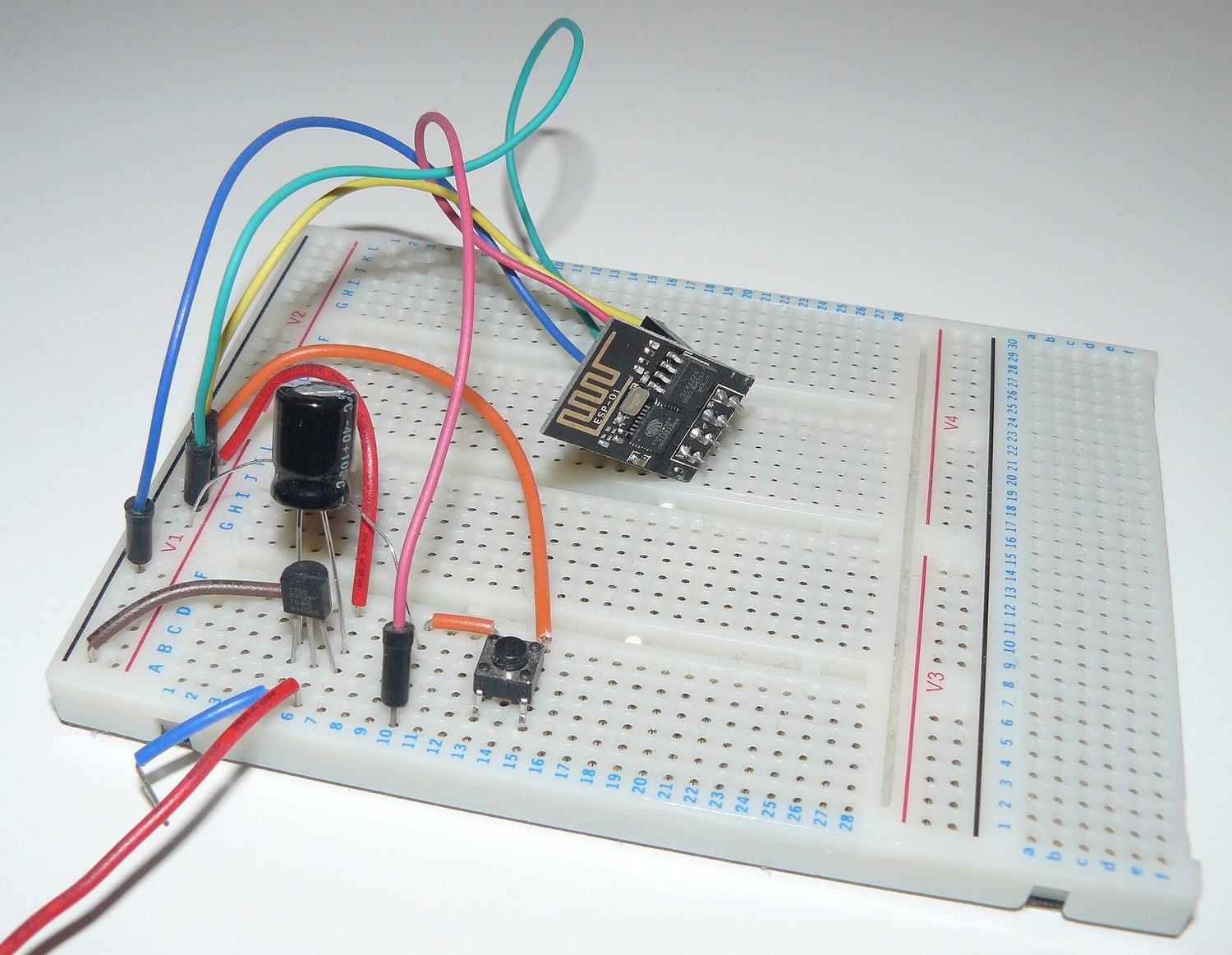
An electronic circuit built on a breadboard A real circuit on a breadboard: a resistor and capacitor together set how fast the voltage rises and falls

Vocabulary Train
English Chinese Pinyin
equivalent capacitance 等效电容 děng xiào diàn róng
RC circuit RC电路 RC diàn lù
time constant 时间常数 shí jiān cháng shù
steady state 稳态 wěn tài
11.8

Exam tips

  • Relate current to charge flow $I=\tfrac{dQ}{dt}$ and use $J=\sigma E$, $R=\tfrac{\rho L}{A}$ for resistance.
  • Apply Kirchhoff's laws (junction: charge; loop: energy) with consistent sign conventions.
  • Analyse RC circuits with calculus: charging/discharging give exponentials with time constant $\tau=RC$.
  • Combine resistors (series add, parallel reciprocal) and track power $P=IV=I^2R$.
  • At $t=0$ a capacitor acts like a wire; after a long time ($t\to\infty$) it acts like an open branch.

Log in or create account

IGCSE & A-Level