In this experiment, you will investigate the refraction of light by a transparent block.
You will determine a quantity known as the refractive index of the material of the block.
Use the separate ray-trace sheet provided.
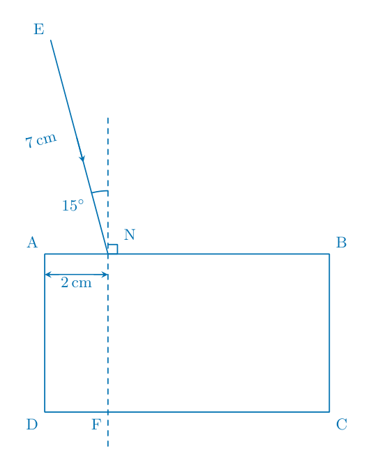
You may refer to Fig. 3.1 for guidance.

Place the transparent block approximately in the centre of the ray-trace sheet. Carefully draw round the block and label the corners A, B, C and D as indicated by Fig. 3.1.
Remove the block from the ray-trace sheet.
Draw a normal to line AB at a point N, 2 cm from A. Extend the normal downwards until it crosses the line CD. Label the point at which it crosses CD with the letter F.
Draw a line NE, as indicated by Fig. 3.1, 7 cm long and at an angle $\theta_1 = 15^\circ$ to the normal.[2]
Replace the block in exactly the same position as in (a).
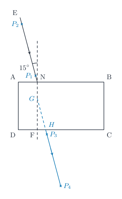
Place two pins $P_1$ and $P_2$ on line NE, a suitable distance apart for accurate ray tracing.
Mark with crosses and label the positions of $P_1$ and $P_2$.
View the images of $P_1$ and $P_2$ through the block, from the direction indicated by the eye in Fig. 3.1. Place two pins $P_3$ and $P_4$ so that pins $P_3$ and $P_4$ and the images of $P_1$ and $P_2$ all appear exactly one behind the other.
Mark with crosses and label the positions of $P_3$ and $P_4$.
Remove the block and pins from the ray-trace sheet.
Draw a straight line through $P_3$ and $P_4$. Extend this line to cross NF.
Label the point at which this line meets NF with the letter G. Label the point at which this line crosses CD with the letter H.[2]
Join points H and N with a straight line.
Measure the length a of line HN.
a = cm
Measure the length b of line HG.
b = cm
Calculate a value n for the refractive index. Use the equation $n = \frac{a}{b}$.
n = [2]
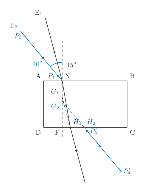
Draw a new line NE, as indicated by Fig. 3.1, 7 cm long and at an angle $\theta_2 = 40^\circ$ to the normal.
Repeat the steps in (b). Extend the new line HG until it crosses the line HG from (b).[1]
Measure $\alpha$, the acute angle between the line HG from (b) and the line HG from (d). (An acute angle is always less than $90^\circ$.)
$\alpha$ = [1]
A student suggests that angle $\alpha$ should be equal to the difference between angle $\theta_2$ from (d) and angle $\theta_1$ from (a).
State whether your results support this suggestion. Justify your answer by reference to values from your results.
statement
justification
[2]
Suggest one technique to use in this type of experiment to ensure results are accurate.
[1]
[Total: 11]
Write your name, centre number and candidate number on your ray-trace sheet.
Tie your ray-trace sheet into this Booklet between pages 8 and 9.