In this experiment, you will investigate the position of the image in a plane mirror.
Use the ray-trace sheet supplied, referring to Fig. 3.1 for guidance.

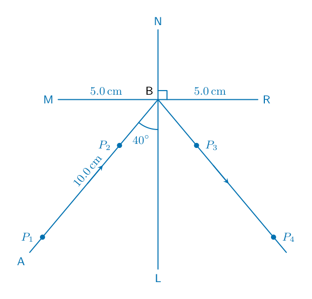
• Draw a line 10.0 cm long near the middle of the ray-trace sheet. Label the line MR. Draw a normal to this line that passes through its centre. Label the normal NL. Label the point at which NL crosses MR with the letter B.
- Draw a line below MR, 10.0 cm long from B at an angle of incidence $i = 40^{\circ}$ to the normal and to the left of the normal. Label the end of this line A.
- Place the reflecting face of the mirror vertically on the line MR.
- Place two pins, $P_1$ and $P_2$, on line AB at a suitable distance apart for this type of ray-trace experiment. Label the positions of $P_1$ and $P_2$.
- View the images of pins $P_1$ and $P_2$ from the direction indicated by the eye in Fig. 3.1. Place two pins, $P_3$ and $P_4$, so that pins $P_3$ and $P_4$ and the images of $P_2$ and $P_1$ all appear exactly one behind the other. Label the positions of $P_3$ and $P_4$. [3]
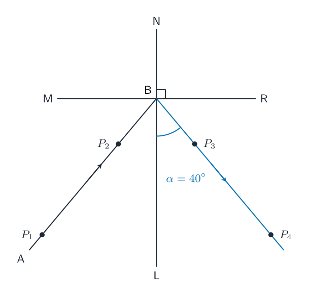
Remove the pins and the mirror. Draw a line through the positions of $P_3$ and $P_4$. Continue the line until it meets MR.
Measure the acute angle $\alpha$ between this line and the normal NL. An acute angle is an angle less than $90^{\circ}$.
$\alpha = ........................................................^{\circ}$[1]
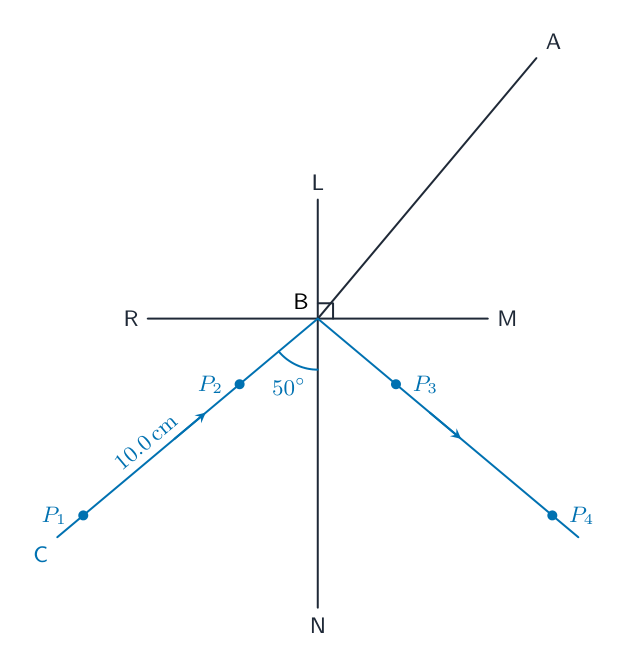
Turn the ray-trace sheet through $180^{\circ}$. See Fig. 3.2.

- Draw a line below MR, 10.0 cm long from B at an angle of incidence $i = 50^{\circ}$ to the normal and to the left of the normal. Label the end of this line C.
- Place pins $P_1$ and $P_2$ on line CB at a suitable distance apart for this type of ray-trace experiment.
- Place the reflecting face of the mirror vertically on the line MR with the centre of the mirror at B.
- View the images of pins $P_1$ and $P_2$ from the direction indicated by the eye in Fig. 3.2.
- Place pins $P_3$ and $P_4$ so that pins $P_3$ and $P_4$ and the images of $P_2$ and $P_1$ all appear exactly one behind the other. Label the new positions of $P_3$ and $P_4$. [2]
Remove the pins and the mirror.
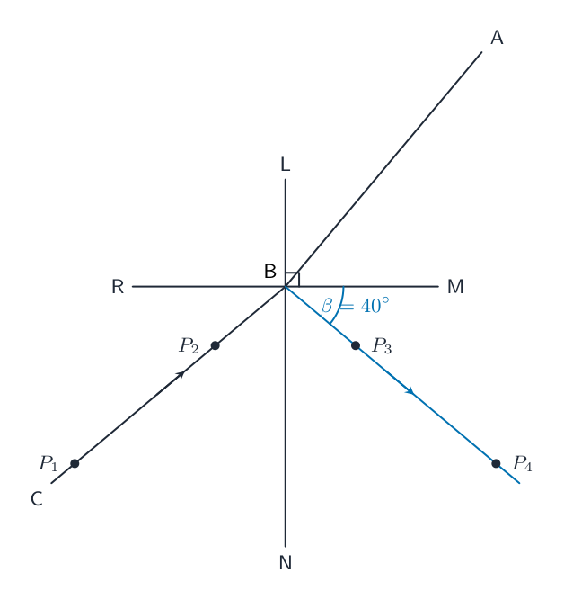
Draw a line through the new positions of $P_3$ and $P_4$. Continue the line until it meets NL.
Measure the acute angle $\beta$ between this line and the horizontal line MR.
$\beta = ........................................................^{\circ}$[1]
Suggest a relationship between $\alpha$ and $\beta$. Justify your answer by reference to the results.
relationship
justification [2]
State two techniques that you use to obtain an accurate ray trace.
1
2 [2]
[Total: 11]