Skip to content

IGCSE Physics · June 2025 · Paper 32 · Difficulty 2 · Core

Question 9

9

Fig. 9.1 shows two resistors connected in series.

Fig. 9.1
(a)

Calculate the combined resistance of the two resistors in series.

combined resistance = Ω[1]

(b)

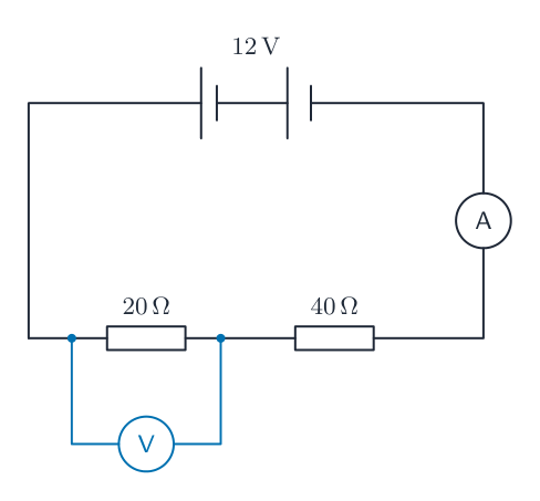
The two resistors in Fig. 9.1 are connected to an ammeter and a 12V battery, as shown in Fig. 9.2.

Fig. 9.2

The reading on the ammeter is 0.20A.

(i)

Calculate the potential difference (p.d.) across the 20Ω resistor.

potential difference = V[3]

(ii)

A student uses a voltmeter to measure the potential difference across the 20Ω resistor.

Draw on Fig. 9.2 to show how the student connects the voltmeter. Use the correct circuit symbol for the voltmeter.[2]

(c)

The student removes the two resistors and then connects them in parallel, as shown in Fig. 9.3.

Fig. 9.3

Suggest a value for the combined resistance of the two resistors in parallel.

combined resistance = Ω[1]

[Total: 7]
Show the mark scheme

These are the official mark-scheme rows. Each point that matches your answer earns a mark.

Tap the mark scheme to open it full size.

Show a worked answer

How to reach each mark, step by step. Try the question yourself first.

9(a)

  • For resistors in series, $R = R_1 + R_2$.
  • $R = 20\,\Omega + 40\,\Omega = \mathbf{60}\,\Omega$.

9(b)(i)

  • Use $V = IR$ for the $20\,\Omega$ resistor.
  • $V = (0.20\,\mathrm{A})(20\,\Omega) = \mathbf{4.0}\,\mathrm{V}$.

9(b)(ii)

  • The $\textbf{voltmeter}$ is connected in parallel across the $20\,\Omega$ resistor, as shown below.
Worked answer drawing

9(c)

  • The combined resistance in parallel is less than the smallest individual resistance; one possible value is $\mathbf{13.3}\,\Omega$.
Original question

Log in or create account

IGCSE, A-Level & AP