Skip to content

IGCSE Physics · June 2025 · Paper 31 · Difficulty 2 · Core

Question 8

8

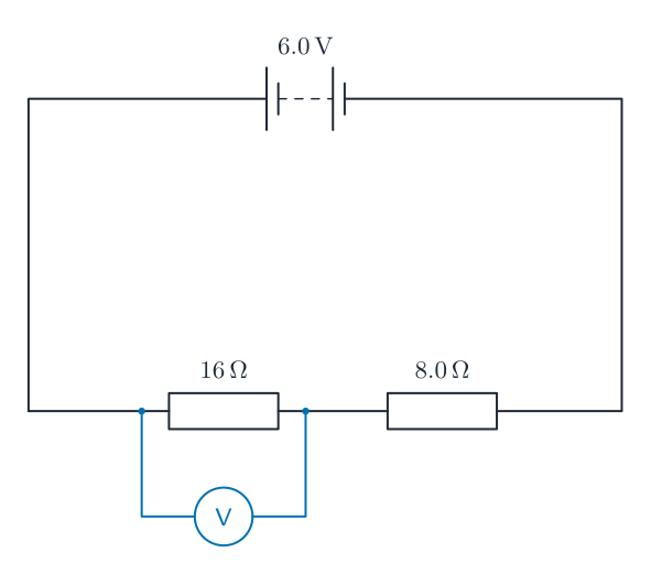
Fig. 8.1 shows the circuit diagram for a $16\,\Omega$ resistor and an $8.0\,\Omega$ resistor connected to a 6.0V battery.

(a)

Calculate the combined resistance of the two resistors shown in Fig. 8.1.

combined resistance = $\Omega$[2]

(b)

The potential difference across the $8.0\,\Omega$ resistor is 2.0V.

Calculate the current in the resistor.

current = A[3]

(c)

State the name of the particles that move through the metal wires when there is a current in the circuit.

[1]

(d)

A student measures the potential difference across the $16\,\Omega$ resistor by using a meter.

On Fig. 8.1, draw the electrical symbol for this meter and its connections.[2]

[Total: 8]
Show the mark scheme

These are the official mark-scheme rows. Each point that matches your answer earns a mark.

Tap the mark scheme to open it full size.

Show a worked answer

How to reach each mark, step by step. Try the question yourself first.

8(a)

  • The resistors are in series, so use $R = R_1 + R_2$.
  • $R = 16\,\Omega + 8.0\,\Omega = \mathbf{24}\,\Omega$.

8(b)

  • Use $V = IR$, so $I = V/R$.
  • $I = (2.0\,\mathrm{V})/(8.0\,\Omega) = \mathbf{0.25}\,\mathrm{A}$.

8(c)

  • The moving particles are electrons.

8(d)

  • Draw a voltmeter symbol, a V inside a circle, connected in parallel across the $16\,\Omega$ resistor.
Worked answer drawing
Original question

Log in or create account

IGCSE, A-Level & AP