Skip to content

IGCSE Physics · June 2021 · Paper 52 · Difficulty 3 · Standard

Question 2

2

In this experiment, you will investigate the position of the image in a plane mirror.

Carry out the following instructions. Use the ray-trace sheet supplied, referring to Fig. 2.1 for guidance.

Fig. 2.1
(a)

• Draw a line 10 cm long near the top of the ray-trace sheet. Label the line MR. Draw a normal to this line that passes through its centre. Label the normal NL. Label the point at which NL crosses MR with the letter B.

  • Draw a line CD 8.0 cm below MR and parallel to MR.
  • Label the point X where CD crosses NL.
  • Draw a line EF 8.0 cm below CD and parallel to CD.
  • Label the point Y where EF crosses NL. [2]

(b)

• Draw a line 7.0 cm long from B at an angle of incidence $\theta_1 = 20^\circ$ to the normal below MR and to the left of the normal. Label the end of this line A.

  • Place two pins, $P_1$ and $P_2$, on line AB at a suitable distance apart for this type of ray-trace experiment. [2]

(c)

Place the reflecting face of the mirror vertically on the line MR.

View the images of pins $P_1$ and $P_2$ from the direction indicated by the eye in Fig. 2.1. Place pin $P_3$ on line CD so that the images of $P_2$ and $P_1$ appear exactly behind pin $P_3$. Label the position of $P_3$.

Place pin $P_4$ on line EF so that pin $P_3$, and the images of $P_2$ and $P_1$, all appear exactly behind pin $P_4$. Label the position of $P_4$.[1]

(d)
(i)

Measure and record the distance $a$ from X to $P_3$.

$a =$ [1]

(ii)

Measure and record the distance $b$ from Y to $P_4$.

$b =$ [1]

(iii)

Calculate $\frac{a}{b}$.

$\frac{a}{b} =$ [1]

(e)

• Repeat the steps in parts (b) and (c) using an angle of incidence $\theta_2 = 10^\circ$.

  • Measure and record the distance $c$ from X to $P_3$.

$c =$

  • Measure and record the distance $d$ from Y to $P_4$.

$d =$

  • Calculate $\frac{c}{d}$.

$\frac{c}{d} =$ [1]

(f)

State and explain whether the values of $\frac{a}{b}$ and $\frac{c}{d}$ can be considered to be equal in this experiment.

[1]

(g)

A student carries out this experiment with care. Suggest a practical reason why the results may not be accurate.

[1]

Tie your ray-trace sheet into this booklet between pages 4 and 5.
Show the mark scheme

These are the official mark-scheme rows. Each point that matches your answer earns a mark.

Tap the mark scheme to open it full size.

Show a worked answer

How to reach each mark, step by step. Try the question yourself first.

2(a)

  • Draw the normal through the centre of MR, at right angles to MR. Label the crossing B.
  • Draw CD parallel to MR, $8.0\,\mathrm{cm}$ below it, and EF parallel to CD, a further $8.0\,\mathrm{cm}$ below. Label their crossings with the normal X and Y.

2(b)

  • Draw BA to the left of the normal, making an angle of $20^\circ$ with it.
  • Place P1 and P2 at least $5.0\,\mathrm{cm}$ apart on BA so that they can be lined up accurately.

2(c)

  • Place P3 on XD so that it lines up with the images of P1 and P2. Place P4 on YF so that it lines up with P3 and both images.

2(d)(i)

  • For an ideal ray trace, the angle of reflection equals the angle of incidence, $20^\circ$. Use your measured distance if it differs slightly.
  • Use $a = BX\tan20^\circ$.
  • $a = (8.0\,\mathrm{cm})\tan20^\circ = \mathbf{2.9}\,\mathrm{cm}$ for the ideal ray.

2(d)(ii)

  • The reflected ray reaches EF at twice the distance below the mirror, so its distance from the normal also doubles.
  • Use $b = BY\tan20^\circ$.
  • $b = (16.0\,\mathrm{cm})\tan20^\circ = \mathbf{5.8}\,\mathrm{cm}$ for an ideal ray trace. Use your own measured distance in the experiment.

2(d)(iii)

  • Use the ratio $a/b$. Divide your measured distances, using the same unit for both.
  • For the ideal ray trace, $a/b = (2.9\,\mathrm{cm})/(5.8\,\mathrm{cm}) = \mathbf{0.50}$. The units cancel.

2(e)

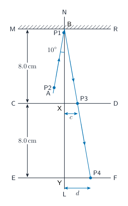
  • Draw BA $7.0\,\mathrm{cm}$ long at $10^\circ$ to the normal. Keep P1 and P2 at least $5.0\,\mathrm{cm}$ apart. Align P3 and P4 with their images; the ideal ray trace is shown below.
  • Use $c = BX\tan10^\circ$ and $d = BY\tan10^\circ$. Your measured distances may differ slightly from these ideal values.
  • $c = (8.0\,\mathrm{cm})\tan10^\circ = \mathbf{1.4}\,\mathrm{cm}$; $d = (16.0\,\mathrm{cm})\tan10^\circ = \mathbf{2.8}\,\mathrm{cm}$.
  • $c/d = (1.4\,\mathrm{cm})/(2.8\,\mathrm{cm}) = \mathbf{0.50}$, with no unit. This equals $a/b$ because BY is twice BX for both rays.
Worked answer drawing

2(f)

  • The ratios can be considered equal if they are close enough to agree within experimental uncertainty.

2(g)

  • The pins have a finite thickness, so it is difficult to line them up exactly.
Original question

Log in or create account

IGCSE, A-Level & AP