| Core | Supplement |
|---|---|
| 1 Describe the forces between magnetic poles and between magnets and magnetic materials, including the use of the terms north pole (N pole), south pole (S pole), attraction and repulsion, magnetised and unmagnetised | 10 Explain that magnetic forces are due to interactions between magnetic fields |
| 2 Describe induced magnetism | |
| 3 State the differences between the properties of temporary magnets (made of soft iron) and the properties of permanent magnets (made of steel | |
| 4 State the difference between magnetic and non-magnetic materials | |
| 5 Describe a magnetic field as a region in which a magnetic pole experiences a force | |
| 6 Draw the pattern and direction of magnetic field lines around a bar magnet | 11 Know that the relative strength of a magnetic field is represented by the spacing of the magnetic field lines |
| 7 State that the direction of a magnetic field at a point is the direction of the force on the N pole of a magnet at that point | |
| 8 Describe the plotting of magnetic field lines with a compass or iron filings and the use of a compass to determine the direction of the magnetic field | |
| 9 Describe the uses of permanent magnets and electromagnets |
Electricity and magnetism
IGCSE Physics · Topic 4
 31:58
31:58
Electricity & Magnetism
Flick a switch and a light comes on. Hold a magnet near iron and it pulls. These two forces — electricity and magnetism — look separate, but they are deeply…
English narration · English + 中文 subtitles burned in
4.1
Magnetism
Syllabus
Source: Cambridge International syllabus
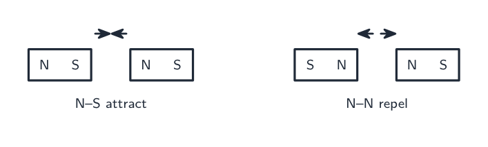
A magnet 磁体 can attract some metals. Every magnet has two ends, called poles 磁极: a north pole 北极 (N pole) and a south pole 南极 (S pole).
The rule for two poles is like the rule for charges:
- Poles that are the same (N and N, or S and S) repel 排斥 (push apart): this is repulsion 排斥力.
- Poles that are different (N and S) attract 吸引 (pull together): this is attraction 吸引力.
A magnet attracts a magnetic material 磁性材料, such as iron, steel, cobalt and nickel. Materials such as copper, plastic and wood are classed as non-magnetic here: they are not strongly attracted by a stationary bar magnet.
Induced magnetism
Put a piece of iron near or touching a magnet, and the iron becomes a magnet itself. This is induced magnetism 感应磁性. The end of the iron nearest the magnet gains the opposite pole, so the two then attract.
Temporary and permanent magnets
- Soft iron 软铁 is easy to magnetise 磁化 but loses its magnetism quickly. It is used for a temporary magnet 临时磁体.
- Steel 钢 is harder to magnetise but keeps its magnetism. It is used for a permanent magnet 永磁体.
An initially unmagnetised 未磁化 soft-iron core is suitable when magnetism should fall quickly after the current stops. Steel is a suitable permanent-magnet material in these examples.
Magnetic fields
A magnetic field 磁场 is a region 区域 where a magnetic pole feels a force. We draw it with magnetic field lines 磁场线:
- The lines come out of the N pole and go into the S pole.
- The field direction at a point is the direction of the force on the N pole of a small test magnet placed there.
- Where the lines are close together the field is strong; where they are far apart the field is weak.

You can show the pattern by sprinkling iron filings 铁屑 on paper over a magnet, or by moving a small plotting compass 指南针 around it (the needle points along the field).

Uses of magnets
- Permanent magnets: fridge door catches, compass needles, loudspeakers.
- Electromagnets 电磁铁 (their field is controlled by current): cranes that lift scrap iron, electric bells, relays. Changing the current controls an electromagnet's field; soft iron reduces remaining magnetism when the current stops.
Magnetic forces happen because the fields of the two magnets push and pull on each other.
Explore
Make the magnetic field visible
Compass needles trace the field from N to S; switch between attract and repel and watch the whole pattern reorganise, with a neutral point appearing for like poles.
Vocabulary
Train
| English |
|---|
| magnet/ˈmæɡnɪt/ |
| poles/pəʊlz/ |
| north pole/nɔːθ pəʊl/ |
| south pole/saʊθ pəʊl/ |
| repel/rɪˈpel/ |
| repulsion/rɪˈpʌlʃn/ |
| attract/əˈtrækt/ |
| attraction/əˈtrækʃn/ |
| magnetic material/mæɡˈnetɪk məˈtɪərɪəl/ |
| induced magnetism/ɪnˈdjuːst ˈmæɡnɪtɪzəm/ |
| soft iron/sɒft ˈaɪən/ |
| magnetise/ˈmæɡnɪtaɪz/ |
| temporary magnet/ˈtemprəri ˈmæɡnɪt/ |
| steel/stiːl/ |
| permanent magnet/ˈpɜːmənənt ˈmæɡnɪt/ |
| unmagnetised/ʌnˈmæɡnɪtaɪzd/ |
| magnetic field/mæɡˈnetɪk fiːld/ |
| region/ˈriːdʒn/ |
| magnetic field lines/mæɡˈnetɪk fiːld laɪnz/ |
| iron filings/ˈaɪən ˈfaɪlɪŋz/ |
| compass/ˈkʌmpəs/ |
| electromagnet/ɪˌlektrəʊˈmæɡnɪt/ |
4.2
Static electricity

Syllabus
4.2.1 Electric charge
| Core | Supplement |
|---|---|
| 1 State that there are positive and negative charges | 7 State that charge is measured in coulombs |
| 2 State that positive charges repel other positive charges, negative charges repel other negative charges, but positive charges attract negative charges | 8 Describe an electric field as a region in which an electric charge experiences a force |
| 3 Describe simple experiments to show the production of electrostatic charges by friction and to show the detection of electrostatic charges | 9 State that the direction of an electric field at a point is the direction of the force on a positive charge at that point |
| 4 Explain that charging of solids by friction involves only a transfer of negative charge (electrons) | 10 Describe simple electric field patterns, including the direction of the field: (a) around a point charge (b) around a charged conducting sphere (c) between two oppositely charged parallel conducting plates (end effects will not be examined) |
| 5 Describe an experiment to distinguish between electrical conductors and insulators | |
| 6 Recall and use a simple electron model to explain the difference between electrical conductors and insulators and give typical examples |
4.2.2 Electric current
| Core | Supplement |
|---|---|
| 1 Know that electric current is related to the flow of charge | 5 Define electric current as the charge passing a point per unit time; recall and use the equation $I = \frac{Q}{t}$ |
| 2 Describe the use of ammeters (analogue and digital) with different ranges | |
| 3 Describe electrical conduction in metals in terms of the movement of free electrons | 6 State that conventional current is from positive to negative and that the flow of free electrons is from negative to positive |
| 4 Know the difference between direct current (d.c.) and alternating current (a.c.) |
4.2.3 Electromotive force and potential difference
| Core | Supplement |
|---|---|
| 1 Define electromotive force (e.m.f.) as the electrical work done by a source in moving a unit charge around a complete circuit | 6 Recall and use the equation for e.m.f. $E = \frac{W}{Q}$ |
| 2 Know that e.m.f. is measured in volts (V) | |
| 3 Define potential difference (p.d.) as the work done by a unit charge passing through a component | 7 Recall and use the equation for p.d. $V = \frac{W}{Q}$ |
| 4 Know that the p.d. between two points is measured in volts (V) | |
| 5 Describe the use of voltmeters (analogue and digital) with different ranges |
4.2.4 Resistance
| Core | Supplement |
|---|---|
| 1 Recall and use the equation for resistance $R = \frac{V}{I}$ | 4 Sketch and explain the current–voltage graphs for a resistor of constant resistance, a filament lamp and a diode |
| 2 Describe an experiment to determine resistance using a voltmeter and an ammeter and do the appropriate calculations | |
| 3 State, qualitatively, the relationship of the resistance of a metallic wire to its length and to its cross-sectional area | 5 Recall and use the following relationship for a metallic electrical conductor: (a) resistance is directly proportional to length (b) resistance is inversely proportional to cross-sectional area |
4.2.5 Electrical energy and electrical power
| Core | Supplement |
|---|---|
| 1 Understand that electric circuits transfer energy from a source of electrical energy, such as an electrical cell or mains supply, to the circuit components and then into the surroundings | |
| 2 Recall and use the equation for electrical power $P = IV$ | |
| 3 Recall and use the equation for electrical energy $E = IVt$ | |
| 4 Define the kilowatt-hour (kWh) and calculate the cost of using electrical appliances where the energy unit is the kWh |
Source: Cambridge International syllabus
There are two kinds of electric charge 电荷: positive charge 正电荷 and negative charge 负电荷. The rule is like the rule for poles — same charges repel, different charges attract.
Charging by friction
When you rub two different materials together, electrons 电子 (tiny negative particles) move from one to the other. This is charging by friction 摩擦起电.
- The material that gains electrons becomes negative.
- The material that loses electrons becomes positive.
In charging solids by friction, electrons transfer; positive nuclei do not move between the solids. If a rod gains electrons from a cloth, it becomes negative and the cloth positive. The direction of transfer depends on the pair of materials.
Detecting a charge. A charged rod picks up small pieces of paper, and it bends a thin stream of water from a tap. Hang one charged rod from a thread and bring another charged rod near it: if the two have the same kind of charge, the hanging rod swings away. Repulsion is the only sure test for a charge, because attraction also happens with uncharged objects.
Conductors and insulators
- A conductor 导体 (copper and other metals) lets charge flow through it easily, because it has free electrons that can move.
- An insulator 绝缘体 (plastic, rubber, glass) does not let charge flow, because its electrons cannot move freely.
In a supervised low-voltage test, place the sample in a working cell-and-lamp circuit. A lit lamp shows enough current passes. If it does not light, first check the connections and the lamp with a known conductor; a fault or a very small current can also prevent lighting.
Electric fields and ions
Charge is measured in coulombs 库仑 (C). An electric field 电场 is a region where an electric charge feels a force. Its direction at a point is the direction of the force on a positive charge. Simple field patterns (the arrows show the direction):
- around a point charge 点电荷: straight lines, pointing away from a positive charge and towards a negative charge;
- around an isolated charged conducting sphere: radial lines, like a point charge outside the sphere;
- between two parallel plates with opposite charges, ignoring edge effects: straight, evenly spaced lines from the positive plate to the negative plate.

An atom is normally neutral. If it loses electrons it becomes a positive ion 离子; if it gains electrons it becomes a negative ion.
Explore
Rub a balloon and watch it charge
Rubbing moves electrons onto the balloon, making it negative — then it attracts a neutral wall or your hair, but repels another negative balloon.
Vocabulary
Train
| English |
|---|
| electric charge/ɪˈlektrɪk tʃɑːdʒ/ |
| positive charge/ˈpɒzɪtɪv tʃɑːdʒ/ |
| negative charge/ˈneɡətɪv tʃɑːdʒ/ |
| electron/ɪˈlektrɒn/ |
| charging by friction/ˈtʃɑːdʒɪŋ baɪ ˈfrɪkʃn/ |
| conductor/kənˈdʌktə/ |
| insulator/ˈɪnsjuːleɪtə/ |
| coulomb/ˈkuːlɒm/ |
| electric field/ɪˈlektrɪk fiːld/ |
| point charge/pɔɪnt tʃɑːdʒ/ |
| ion/ˈaɪɒn/ |
4.2
Electric current
An electric current 电流 is a flow of electric charge. It is measured in amperes 安培 (A) with an ammeter 电流表, joined in series in the circuit.
An analogue 模拟 ammeter has a needle that moves over a scale; a digital 数字 ammeter shows the reading as a number. Both come with different ranges 量程. Start with a range high enough to avoid overloading the meter, then use a suitable lower range that still includes the reading: a 0–1 A range for a current of about 0.4 A, or a 0–100 mA range for a few milliamps.
Current is the charge that passes a point each second:
$$I = \frac{Q}{t}$$
Here $I$ is current (A), $Q$ is charge (C) and $t$ is time (s). Rearranged, $Q = It$.
Worked example. A current of $3.0\ \text{A}$ flows through a lamp for $20\ \text{s}$. How much charge passes through it?
Known: $I=3.0\ \text{A}$ and $t=20\ \text{s}$. Current is charge per unit time, so rearrange $I=Q/t$:
$$Q=It$$
$$Q=(3.0\ \text{A})(20\ \text{s})=60\ \text{C}$$
In a metal the current is a flow of free electrons 自由电子. There are two "directions" to know:
- Conventional current 常规电流 is taken to flow from + to − round the outside of the cell.
- The free electrons really drift the other way, from − to +.
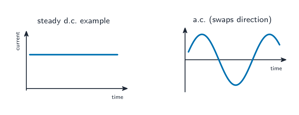
A direct current 直流电 (d.c.) flows in one direction; its size need not be constant. A steady battery current is one example. An alternating current 交流电 (a.c.) keeps swapping direction many times each second, as from the mains supply 市电.
Vocabulary
Train
| English |
|---|
| electric current/ɪˈlektrɪk ˈkʌrənt/ |
| ampere/ˈæmpeə/ |
| ammeter/ˈæmiːtə/ |
| analogue/ˈænəlɒɡ/ |
| digital/ˈdɪdʒɪtl/ |
| ranges/ˈreɪndʒɪz/ |
| free electrons/friː ɪˈlektrɒnz/ |
| conventional current/kənˈvenʃənl ˈkʌrənt/ |
| direct current/daɪˈrekt ˈkʌrənt/ |
| alternating current/ˈɔːltəneɪtɪŋ ˈkʌrənt/ |
| mains supply/meɪnz səˈplaɪ/ |
4.2
E.m.f. and potential difference

A cell gives energy 能量 to the charges that move through it. Two quantities describe this, and both are measured in volts 伏特 (V).
- The electromotive force 电动势 (e.m.f.) of a source is the electrical work it does to drive unit charge all the way round a complete circuit 电路.
- The potential difference 电势差 (p.d.) across a component is the work done by unit charge as it passes through that component.
A voltmeter 电压表 measures e.m.f. or p.d. It is joined in parallel (across the component). Like ammeters, voltmeters are analogue or digital and have different ranges: pick the range just above the largest voltage you expect.
Both are work done per unit charge:
$$E = \frac{W}{Q}, \qquad V = \frac{W}{Q}$$
where $W$ is the energy transferred (J) and $Q$ is the charge (C). For a source giving $W=120\ \text{J}$ to $Q=60\ \text{C}$, use work per unit charge:
$$E=\frac{W}{Q}$$
$$E=\frac{120\ \text{J}}{60\ \text{C}}=2.0\ \text{V}$$
Here $E$ denotes e.m.f. in volts; in the energy section $E$ denotes energy in joules. Read the context and unit.
Vocabulary
Train
| English |
|---|
| energy/ˈenədʒi/ |
| volt/vəʊlt/ |
| electromotive force/ɪˌlektrəʊˈməʊtɪv fɔːs/ |
| circuit/ˈsɜːkɪt/ |
| potential difference/pəˈtenʃl ˈdɪfrəns/ |
| voltmeter/ˈvəʊltmiːtə/ |
4.2
Resistance

Resistance 电阻 measures how hard it is for current to flow. At the same p.d., a bigger resistance gives a smaller current. It is measured in ohms 欧姆 (Ω).
$$R = \frac{V}{I}$$
Measuring resistance. Connect the component in series with a cell, a switch, an ammeter and a variable resistor 可变电阻器, and connect a voltmeter across the component. Close the switch, read $I$ and $V$, then change the variable resistor to get several more pairs of readings. For a resistor held at constant temperature, repeated $R=V/I$ values can be compared and averaged. A $V$-against-$I$ graph has gradient $R$; an $I$-against-$V$ graph has gradient $1/R$. For a heating filament, resistance changes, so averaging across different operating temperatures would hide the change.
Worked example. A $12\ \text{V}$ battery drives a current of $0.50\ \text{A}$ through a lamp. Find the lamp's resistance.
Use the p.d.-to-current ratio at this operating point:
$$R=\frac{V}{I}$$
$$R=\frac{12\ \text{V}}{0.50\ \text{A}}=24\ \Omega$$
For wires of the same metal at constant temperature:
- a longer wire has a bigger resistance — resistance is directly proportional 成正比 to length, $R \propto l$;
- a thicker wire has a smaller resistance — resistance is inversely proportional 成反比 to cross-sectional area 横截面积, $R \propto \dfrac{1}{A}$.
So doubling the length doubles the resistance; doubling the area halves it. (Area depends on the diameter squared, so a small change in diameter changes the resistance a lot.)
Current–voltage graphs show how three components behave:
| Component | Shape of the I–V graph | What it tells you |
|---|---|---|
| resistor 电阻器 (fixed) | straight line through the origin | resistance is constant, so $I \propto V$ |
| filament lamp 灯丝灯泡 | S-shaped, getting flatter as $V$ rises | the wire heats up, so its resistance rises |
| diode 二极管 | current one way only | very high resistance the "wrong" way |
Explore
Ohm's law
V = IR
For the configured V-against-I graph, gradient is resistance R; reversing axes gives 1/R.
Explore
I–V characteristics
A resistor gives a straight line; a filament lamp and a diode do not. Pick a component and read I and R off the curve.
Explore
Resistance
V = R·I
Ohm's law: voltage is proportional to current — the gradient is the resistance R.
Vocabulary
Train
| English |
|---|
| resistance/rɪˈzɪstəns/ |
| ohm/əʊm/ |
| variable resistor/ˈveərɪəbl rɪˈzɪstə/ |
| directly proportional/daɪˈrektli prəˈpɔːʃənl/ |
| inversely proportional/ɪnˈvɜːsli prəˈpɔːʃənl/ |
| cross-sectional area/krɒs ˈsekʃənl ˈeərɪə/ |
| resistor/rɪˈzɪstə/ |
| filament lamp/ˈfɪləmənt læmp/ |
| diode/ˈdaɪəʊd/ |
4.2
Electrical energy and power
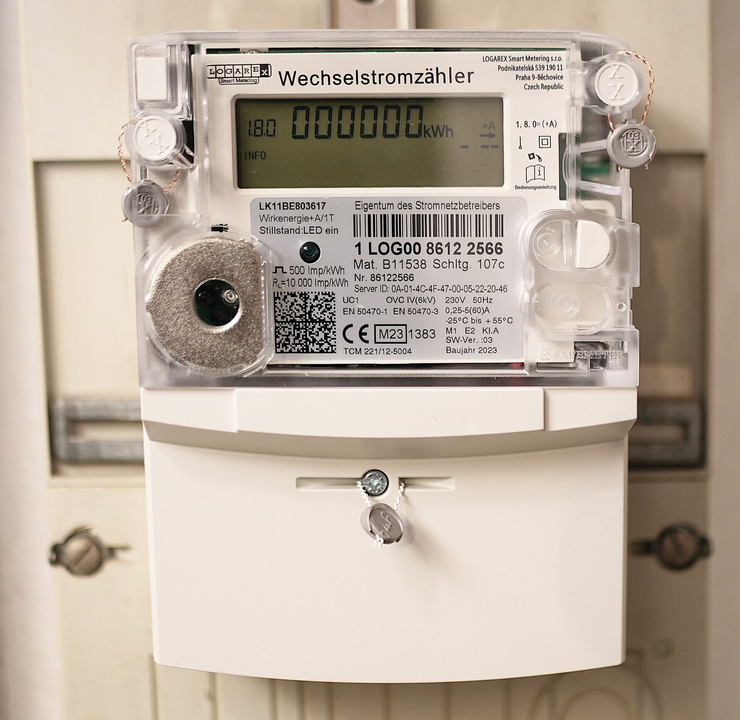
A circuit transfers energy from a source (a cell or the mains) to the components, and then into the surroundings (often as heat, light or sound).
Electrical power 电功率 is the energy transferred each second, measured in watts 瓦特 (W):
$$P = IV$$
The electrical energy 电能 transferred in a time $t$, measured in joules 焦耳 (J), is:
$$E = IVt$$
Worked example. A $12\ \text{V}$ motor draws a current of $2.0\ \text{A}$. Find its power, and the energy it transfers in $30\ \text{s}$.
Power is energy transferred per second. Known: $I=2.0\ \text{A}$, $V=12\ \text{V}$, $t=30\ \text{s}$.
$$P=IV$$
$$P=(2.0\ \text{A})(12\ \text{V})=24\ \text{W}$$
$$E=Pt$$
$$E=(24\ \text{W})(30\ \text{s})=720\ \text{J}$$
The kilowatt-hour
Home electricity bills use a bigger energy unit, the kilowatt-hour 千瓦时 (kWh). One kilowatt-hour is the energy used by a $1\ \text{kW}$ appliance 电器 in $1$ hour.
$$\text{energy (kWh)} = \text{power (kW)} \times \text{time (h)}$$
$$\text{cost} = \text{energy (kWh)} \times \text{price per kWh}$$
For a $2\ \text{kW}$ heater 加热器 used for $3\ \text{h}$ at a fictional price of $20$ cents per kWh:
$$E=Pt$$
$$E=(2\ \text{kW})(3\ \text{h})=6\ \text{kWh}$$
$$\text{cost}=E\times\text{price per kWh}$$
$$\text{cost}=(6\ \text{kWh})(20\ \text{cents/kWh})=120\ \text{cents}$$
Vocabulary
Train
| English |
|---|
| electrical power/ɪˈlektrɪkl ˈpaʊə/ |
| watt/wɒt/ |
| electrical energy/ɪˈlektrɪkl ˈenədʒi/ |
| joule/dʒuːl/ |
| kilowatt-hour/ˈkɪləwɒt ˈaʊə/ |
| appliance/əˈplaɪəns/ |
| heater/ˈhiːtə/ |
4.3
Circuits
Syllabus
4.3.1 Circuit diagrams and circuit components
| Core | Supplement |
|---|---|
| 1 Draw and interpret circuit diagrams containing cells, batteries, power supplies, generators, potential dividers, switches, resistors (fixed and variable), heaters, thermistors (NTC only), light-dependent resistors (LDRs), lamps, motors, bells, ammeters, voltmeters, magnetising coils, transformers, fuses and relays and know how these components behave in the circuit | 2 Draw and interpret circuit diagrams containing diodes and light-emitting diodes (LEDs) and know how these components behave in the circuit |
4.3.2 Series and parallel circuits
| Core | Supplement |
|---|---|
| 1 Know that the current at every point in a series circuit is the same | 8 Recall and use in calculations, the fact that: (a) the sum of the currents entering a junction in a parallel circuit is equal to the sum of the currents that leave the junction (b) the total p.d. across the components in a series circuit is equal to the sum of the individual p.d.s across each component (c) the p.d. across an arrangement of parallel resistances is the same as the p.d. across one branch in the arrangement of the parallel resistances |
| 2 Know how to construct and use series and parallel circuits | |
| 3 Calculate the combined e.m.f. of several sources in series | |
| 4 Calculate the combined resistance of two or more resistors in series | |
| 5 State that, for a parallel circuit, the current from the source is larger than the current in each branch | 9 Explain that the sum of the currents into a junction is the same as the sum of the currents out of the junction |
| 6 State that the combined resistance of two resistors in parallel is less than that of either resistor by itself | 10 Calculate the combined resistance of two resistors in parallel |
| 7 State the advantages of connecting lamps in parallel in a lighting circuit |
4.3.3 Action and use of circuit components
| Core | Supplement |
|---|---|
| 1 Know that the p.d. across an electrical conductor increases as its resistance increases for a constant current | 2 Describe the action of a variable potential divider |
| 3 Recall and use the equation for two resistors used as a potential divider $$\frac{R_1}{R_2} = \frac{V_1}{V_2}$$ |
Source: Cambridge International syllabus
Circuit components
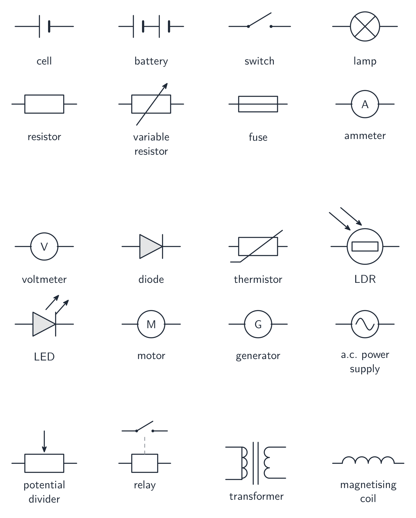
You should know these components and how they behave:
| Component | What it does |
|---|---|
| cell 电池 / battery 电池组 | drives current round the circuit (a battery is two or more cells) |
| power supply 电源 | a source of d.c. or a.c. |
| switch 开关 | breaks or completes the circuit |
| resistor (fixed) | gives a fixed resistance |
| variable resistor | a resistance you can change, to control the current |
| fuse 保险丝 | melts and breaks the circuit if the current is too big |
| lamp / heater | turns electrical energy into light / into heat |
| thermistor 热敏电阻 | the NTC type studied here falls in resistance when hotter |
| light-dependent resistor 光敏电阻 (LDR) | its resistance falls as the light gets brighter |
| diode / light-emitting diode 发光二极管 (LED) | lets current one way only; an LED also gives out light |
| relay 继电器 | a switch worked by an electromagnet (small current controls a big one) |
| motor 电动机 | turns electrical energy into movement |
| bell 电铃 | makes a sound |
| transformer 变压器 | changes the size of an a.c. voltage |
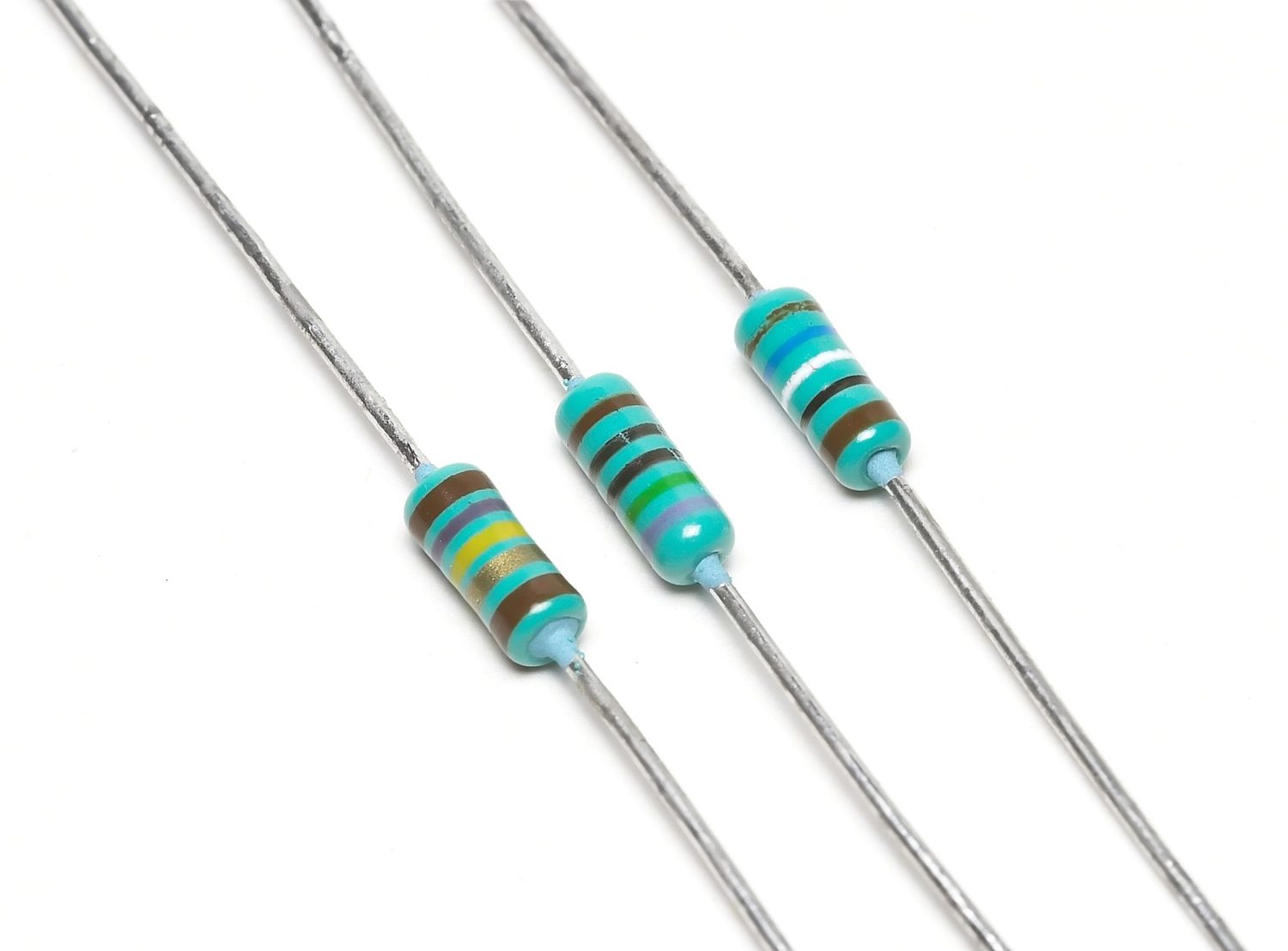
Series and parallel
In a series 串联 circuit the parts form one single loop:
- the current is the same at every point;
- the supply p.d. is shared between the components;
- cells in series add their e.m.f.s (when they point the same way);
- resistors in series add up: $R_{\text{total}} = R_1 + R_2 + \dots$
In a parallel 并联 circuit the parts are on separate branches:
- each branch gets the full supply p.d.;
- the current splits, so the current from the source is bigger than the current in any one branch;
- the total resistance 总电阻 is less than the smallest single resistance.
Lamps in a home are wired in parallel: each gets the full voltage, and if one fails the others stay on.

For calculations (with the rules above):
- at a junction 节点, the total current flowing in equals the total current flowing out;
- in series, the supply p.d. equals the sum of the p.d.s across the components;
- in parallel, the p.d. across each branch is the same;
- two resistors in parallel combine as
$$\frac{1}{R_{\text{total}}} = \frac{1}{R_1} + \frac{1}{R_2}$$
Worked example. A $6\ \Omega$ resistor and a $3\ \Omega$ resistor are connected in parallel. Find their combined resistance.
Use the parallel-resistance relation because both resistors have the same p.d.:
$$\frac{1}{R_{\text{total}}}=\frac{1}{R_1}+\frac{1}{R_2}$$
$$\frac{1}{R_{\text{total}}}=\frac{1}{6\ \Omega}+\frac{1}{3\ \Omega}=\frac{1}{2\ \Omega}$$
$$R_{\text{total}}=2\ \Omega$$
Notice the combined resistance ($2\ \Omega$) is smaller than the smaller of the two resistors.
Potential dividers
Two resistors in series share the supply voltage. This is a potential divider 分压器. For the same current, a bigger resistance has a bigger p.d. across it, so the bigger resistor takes the bigger share:
$$\frac{R_1}{R_2} = \frac{V_1}{V_2}$$
A variable potential divider uses a movable contact to change the output voltage smoothly, for example from $0\ \text{V}$ up to the full supply. If you use a thermistor or an LDR as one of the resistors, the output voltage changes with temperature or light — handy for switching a heater or a lamp on and off automatically.
Explore
Build the current with Ohm's law
Turn up the voltage and the electrons speed up and the bulb glows brighter; add resistance and the current drops. I = V/R, brightness = power.
Vocabulary
Train
| English |
|---|
| cell/sel/ |
| battery/ˈbætəri/ |
| power supply/ˈpaʊə səˈplaɪ/ |
| switch/swɪtʃ/ |
| fuse/fjuːz/ |
| thermistor/ˈθɜːmɪstə/ |
| light-dependent resistor/laɪt dɪˈpendənt rɪˈzɪstə/ |
| light-emitting diode/laɪt ɪˈmɪtɪŋ ˈdaɪəʊd/ |
| relay/ˈriːleɪ/ |
| motor/ˈməʊtə/ |
| bell/bel/ |
| transformer/trænsˈfɔːmə/ |
| series/ˈsɪəriːz/ |
| parallel/ˈpærəlel/ |
| total resistance/ˈtəʊtl rɪˈzɪstəns/ |
| junction/ˈdʒʌŋkʃn/ |
| potential divider/pəˈtenʃl dɪˈvaɪdə/ |
4.4
Electrical safety
Syllabus
| Core | Supplement |
|---|---|
| 1 State the hazards of: (a) damaged insulation (b) overheating cables (c) damp conditions (d) excess current from overloading of plugs, extension leads, single and multiple sockets when using a mains supply | |
| 2 Know that a mains circuit consists of a live wire (line wire), a neutral wire and an earth wire and explain why a switch must be connected to the live wire for the circuit to be switched off safely | |
| 3 Explain the use and operation of trip switches and fuses and choose appropriate fuse ratings and trip switch settings | |
| 4 Explain why the outer casing of an electrical appliance must be either non-conducting (double-insulated) or earthed | |
| 5 State that a fuse without an earth wire protects the circuit and the cabling for a double-insulated appliance |
Source: Cambridge International syllabus
A home is fed by the mains. The mains is dangerous if it is used wrongly.
Hazards
These are hazards 危险 (dangers) with mains electricity:
- damaged insulation 绝缘层 — bare wires can give a shock or start a fire;
- overheating 过热 cables — too much current makes a cable hot, which can start a fire;
- damp 潮湿 conditions — water lets current pass into a person, raising the risk of a shock;
- overloading 过载 — plugging too many appliances into one socket 插座 draws too much current.
Live, neutral and earth
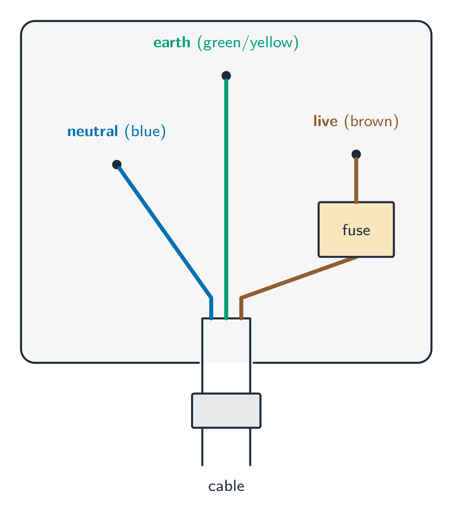
A mains cable has three wires:
- the live wire 火线 carries the high voltage;
- the neutral wire 零线 completes the circuit at about zero voltage;
- the earth wire 地线 is a safety wire joined to the ground.
A switch (and a fuse) must be fitted in the live wire. Opening that switch disconnects the appliance from the live supply in the circuit model. A switch being off is not proof that real equipment is safe to open or work on.
Fuses, trip switches and earthing
A fuse is a thin wire that melts if the current gets too big, breaking the circuit before the cable overheats. For a simplified exam choice, select a fuse rating 额定值 above normal working current and appropriate for the stated cable and appliance limits. For real equipment, use the specified protection.
An overcurrent trip switch 跳闸开关 (circuit breaker) opens the circuit when excessive current is detected and can be reset after the fault is corrected. Operating time depends on the device and fault; it is not always faster than every fuse.
The metal casing 外壳 of an appliance must be made safe in one of two ways:
- earthed 接地: the casing is joined to the earth wire. If a live wire touches the casing, a large current flows to earth and blows the fuse.
- double-insulated 双重绝缘: double or reinforced insulation separates the user from live parts; a non-conducting outer casing is a common example. A plastic-looking case alone does not establish double insulation. Such an appliance needs no protective earth connection; its fuse still protects circuit cabling.

Explore
Electrical safety route
Follow fault current and see how safety devices protect people.
Vocabulary
Train
| English |
|---|
| hazard/ˈhæzəd/ |
| insulation/ˌɪnsjuːˈleɪʃn/ |
| overheating/ˌəʊvəˈhiːtɪŋ/ |
| damp/dæmp/ |
| overloading/ˌəʊvəˈləʊdɪŋ/ |
| socket/ˈsɒkɪt/ |
| live wire/laɪv ˈwaɪə/ |
| neutral wire/ˈnjuːtrəl ˈwaɪə/ |
| earth wire/ɜːθ ˈwaɪə/ |
| fuse rating/fjuːz ˈreɪtɪŋ/ |
| trip switch/trɪp swɪtʃ/ |
| casing/ˈkeɪsɪŋ/ |
| earthed/ɜːθt/ |
| double-insulated/ˈdʌbl ˈɪnsjuːleɪtɪd/ |
4.5
Electromagnetic effects

Syllabus
4.5.1 Electromagnetic induction
| Core | Supplement |
|---|---|
| 1 Know that a conductor moving across a magnetic field or a changing magnetic field linking with a conductor can induce an e.m.f. in the conductor | 4 Know that the direction of an induced e.m.f. opposes the change causing it |
| 2 Describe an experiment to demonstrate electromagnetic induction | 5 State and use the relative directions of force, field and induced current |
| 3 State the factors affecting the magnitude of an induced e.m.f. |
4.5.2 The a.c. generator
| Core | Supplement |
|---|---|
| 1 Describe a simple form of a.c. generator (rotating coil or rotating magnet) and the use of slip rings and brushes where needed | |
| 2 Sketch and interpret graphs of e.m.f. against time for simple a.c. generators and relate the position of the generator coil to the peaks, troughs and zeros of the e.m.f. |
4.5.3 Magnetic effect of a current
| Core | Supplement |
|---|---|
| 1 Describe the pattern and direction of the magnetic field due to currents in straight wires and in solenoids | 4 State the qualitative variation of the strength of the magnetic field around straight wires and solenoids |
| 2 Describe an experiment to identify the pattern of the magnetic field (including direction) due to currents in straight wires and in solenoids | |
| 3 Describe how the magnetic effect of a current is used in relays and loudspeakers and give examples of their application | 5 Describe the effect on the magnetic field around straight wires and solenoids of changing the magnitude and direction of the current |
4.5.4 Force on a current-carrying conductor
| Core | Supplement |
|---|---|
| 1 Describe an experiment to show that a force acts on a current-carrying conductor in a magnetic field, including the effect of reversing: (a) the current (b) the direction of the field | 2 Recall and use the relative directions of force, magnetic field and current |
| 3 Determine the direction of the force on beams of charged particles in a magnetic field |
4.5.5 The d.c. motor
| Core | Supplement |
|---|---|
| 1 Know that a current-carrying coil in a magnetic field may experience a turning effect and that the turning effect is increased by increasing: (a) the number of turns on the coil (b) the current (c) the strength of the magnetic field | 2 Describe the operation of an electric motor, including the action of a split-ring commutator and brushes |
4.5.6 The transformer
| Core | Supplement |
|---|---|
| 1 Describe the construction of a simple transformer with a soft-iron core, as used for voltage transformations | 6 Explain the principle of operation of a simple iron-cored transformer |
| 2 Use the terms primary, secondary, step-up and step-down | |
| 3 Recall and use the equation $$\frac{V_p}{V_s} = \frac{N_p}{N_s}$$ where p and s refer to primary and secondary |
7 Recall and use the equation for 100% efficiency in a transformer $$I_p V_p = I_s V_s$$ where p and s refer to primary and secondary |
| 4 Describe the use of transformers in high-voltage transmission of electricity | |
| 5 State the advantages of high-voltage transmission | 8 Recall and use the equation $$P = I^2 R$$ to explain why power losses in cables are smaller when the voltage is greater |
Source: Cambridge International syllabus
The magnetic effect of a current
A current in a wire makes a magnetic field around it.
- Around a straight wire the field lines are circles around the wire; the field is stronger close to the wire. Reverse the current and the field reverses.
- A solenoid 螺线管 (a long coil 线圈 of wire) makes a field just like a bar magnet, with a N pole at one end and a S pole at the other. The field inside is strong and even.
You can show both patterns with iron filings or a plotting compass. For a solenoid of fixed length, increasing current or turns, or adding a soft-iron core, strengthens the field. Around a straight wire, the field strengthens with current and weakens with distance.
The magnetic effect is used in a relay and in a loudspeaker. In a relay, a small current in a coil magnetises a soft-iron core, which pulls a switch closed in a second circuit. The second circuit can carry a large current, so a small switch or a sensor can safely control a motor or a heater (for example, the ignition switch of a car starts its motor through a relay). In a loudspeaker 扬声器 a changing current in a coil makes the coil push and pull a paper cone, which moves the air and makes sound.
Electromagnetic induction
When a wire moves across a magnetic field, or the field through a coil changes, an e.m.f. is induced in the wire. If the wire is part of a complete circuit, this e.m.f. drives a current. This is electromagnetic induction 电磁感应.
To show it: move a magnet in and out of a coil joined to a sensitive meter, and watch the needle flick. The induced e.m.f. is bigger when you use a stronger magnet, move faster, or use more turns on the coil. The induced e.m.f. always acts to oppose the change that causes it. For a wire moving upward across a rightward field in a closed circuit, the right-hand rule gives induced conventional current into the page. Its motor-effect force is downward, opposing the motion. The direction of the induced current is given by Fleming's right-hand rule 弗莱明右手定则: hold the thumb, first finger and second finger of the right hand at right angles to one another; the thumb points along the motion of the wire, the first finger along the field (N to S), and the second finger then gives the induced current.
The a.c. generator
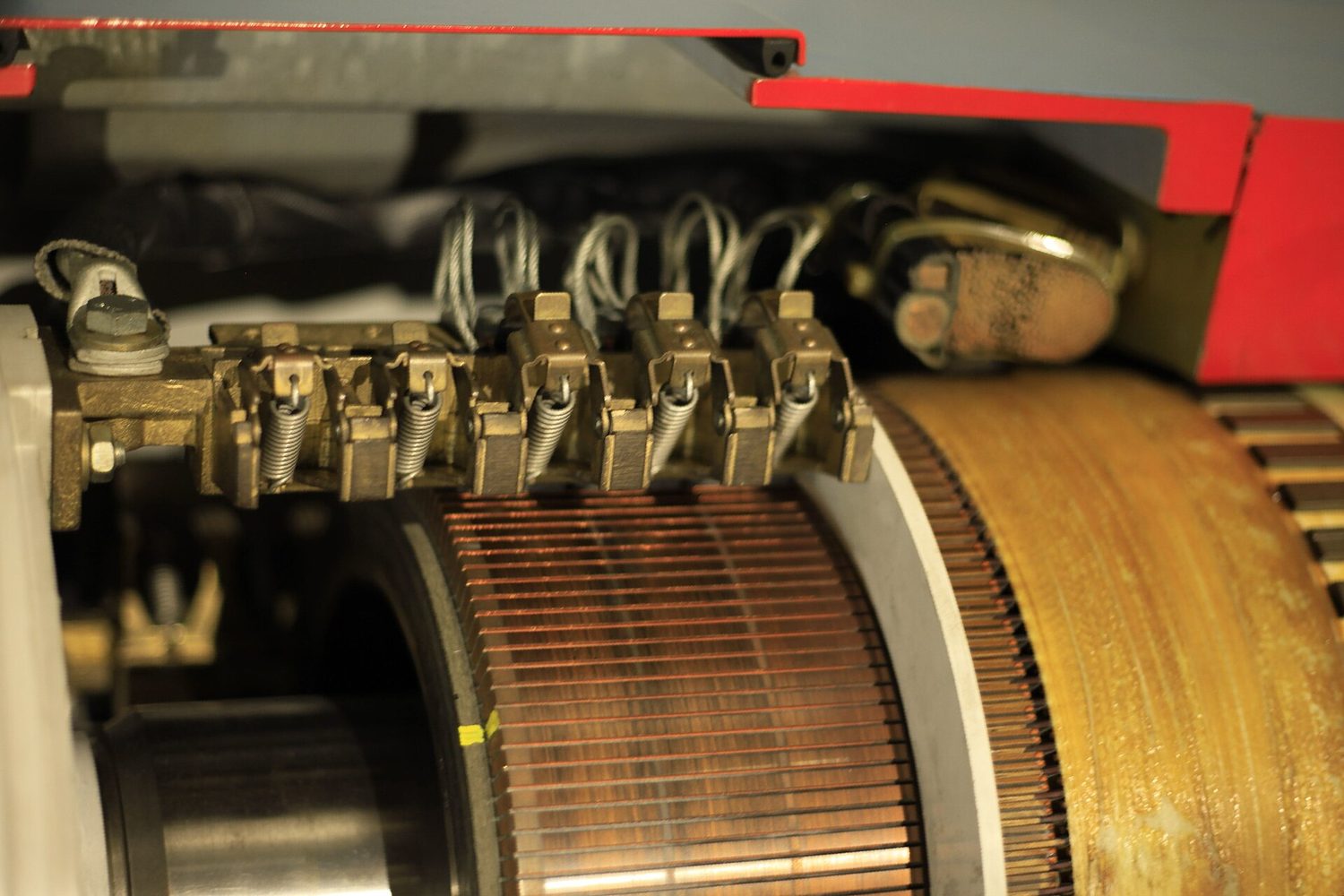
An a.c. generator 交流发电机 turns movement into electricity. A coil is spun in a magnetic field (or a magnet is spun near a coil). As it turns, the field through the coil keeps changing, so an alternating e.m.f. is induced.
- Slip rings 滑环 and carbon brushes 电刷 carry the current out to the circuit while the coil keeps turning.
- For a coil rotating at constant speed, the e.m.f. magnitude is greatest when the coil's plane is parallel to the magnetic field, and zero when its plane is perpendicular to the field. “Flat” and “upright” depend on how a diagram is drawn, so use the field direction as the reference. So the e.m.f.–time graph is a wave: peak, zero, opposite peak, zero, for each turn.

Force on a current-carrying conductor
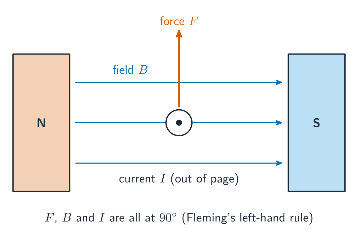
When a current-carrying wire lies in a magnetic field, the field of the wire and the field of the magnet push on each other, so the wire feels a force. This is the motor effect.
- Reverse the current, or reverse the field, and the force reverses.
- Make the current bigger or the field stronger, and the force is bigger.
For a conductor perpendicular to the field, the force is perpendicular to both field and current. A conductor parallel to the field has no motor-effect force. You can find the force direction with Fleming's left-hand rule 弗莱明左手定则: thumb = force (motion), first finger = field (N to S), second finger = current.
Showing the force. Lay a stiff copper wire (or a strip of aluminium foil) between the poles of a U-shaped magnet and connect it to a cell through a switch. When the current flows, the wire jumps up or down. Reverse the cell and the wire jumps the other way; turn the magnet over and it reverses again. A bigger current or a stronger magnet gives a bigger jump.
A moving stream of charged particles acts as a current, so motion across a magnetic field can produce a sideways force — it deflects 偏转 the beam. (Remember electrons flow opposite to the conventional current.)
The d.c. motor
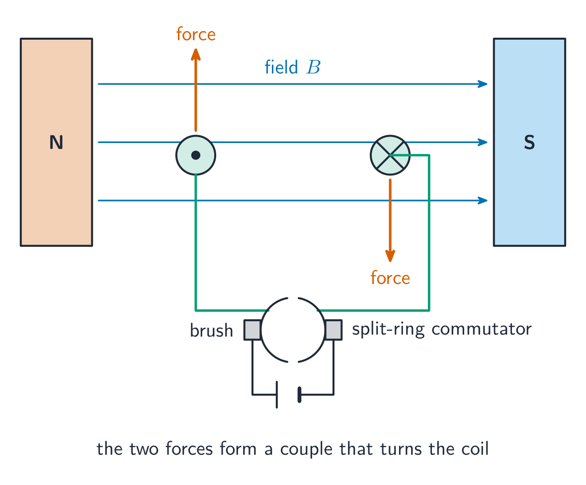
A coil carrying a current in a magnetic field feels a turning effect 转动效应, because the forces on its two sides act in opposite directions. This is a d.c. motor 直流电动机. The turning effect is bigger with more turns on the coil, a bigger current, or a stronger field.
A split-ring commutator 换向器 swaps the current direction in the coil every half-turn. This keeps the coil turning the same way instead of stopping after half a turn.
The transformer
A transformer changes the size of an a.c. voltage. It has two coils wound on a soft-iron core 软铁芯:
- the primary coil 原线圈 takes in the a.c. voltage;
- the secondary coil 副线圈 gives out the changed voltage.
The a.c. in the primary makes a changing magnetic field in the core. The core carries this field to the secondary, where it induces an a.c. e.m.f. The voltages and the numbers of turns are linked by:
$$\frac{V_p}{V_s} = \frac{N_p}{N_s}$$
Worked example. A transformer has $1200$ turns on the primary coil and $100$ turns on the secondary coil. The primary is connected to a $240\ \text{V}$ a.c. supply. Find the secondary voltage.
Use the voltage-to-turns ratio, then rearrange for the secondary voltage:
$$\frac{V_p}{V_s}=\frac{N_p}{N_s}$$
$$V_s=V_p\frac{N_s}{N_p}$$
$$V_s=(240\ \text{V})\frac{100}{1200}=20\ \text{V}$$
Fewer turns on the secondary, so this is a step-down transformer.
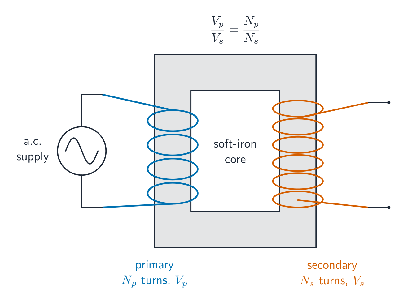

If the secondary has more turns it is a step-up 升压 transformer (voltage rises); fewer turns make a step-down 降压 transformer (voltage falls). For example, a transformer changing $240\ \text{V}$ to $12\ \text{V}$ is a step-down type, and the primary has $20$ times as many turns as the secondary.
If a transformer is 100% efficient, the power in equals the power out:
$$I_p V_p = I_s V_s$$
So a step-up transformer raises the voltage but lowers the current.
Why we use high voltage to send power
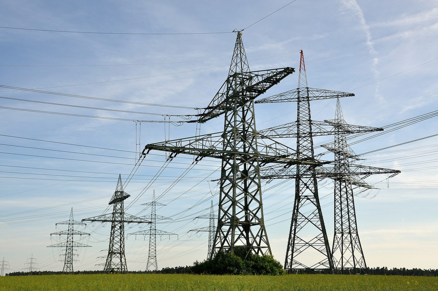
Electricity is sent across the country by high-voltage transmission 高压输电. The power lost as heat in the cables is
$$P = I^2 R$$
where $R$ is the resistance of the cables. A step-up transformer raises the voltage and so lowers the current for the same power ($P = IV$). A smaller current means much less power wasted in the cables. A step-down transformer then lowers the voltage for domestic supply; mains voltage remains hazardous.
Explore
The force that spins a motor
For perpendicular current and field, force is perpendicular to both; reversing either reverses force.
Explore
The generator
V = a sin(bt)
A spinning coil induces a sinusoidal voltage — the AC output.
Explore
Transformer
The ideal voltage ratio equals the turns ratio; a changing primary field is needed.
Vocabulary
Train
| English |
|---|
| solenoid/ˈsəʊlənɔɪd/ |
| coil/kɔɪl/ |
| loudspeaker/ˈlaʊdspiːkə/ |
| electromagnetic induction/ɪˌlektrəʊməɡˈnetɪk ɪnˈdʌkʃn/ |
| Fleming's right-hand rule/ˈflemɪŋz raɪt hænd ruːl/ |
| a.c. generator/ˌeɪ ˈsiː ˈdʒenəreɪtə/ |
| slip rings/slɪp rɪŋz/ |
| brushes/ˈbrʌʃɪz/ |
| Fleming's left-hand rule/ˈflemɪŋz left hænd ruːl/ |
| deflect/dɪˈflekt/ |
| turning effect/ˈtɜːnɪŋ ɪˈfekt/ |
| d.c. motor/ˌdiː ˈsiː ˈməʊtə/ |
| split-ring commutator/splɪt rɪŋ ˈkɒmjuːteɪtə/ |
| soft-iron core/sɒft ˈaɪən kɔː/ |
| primary coil/ˈpraɪməri kɔɪl/ |
| secondary coil/ˈsekəndəri kɔɪl/ |
| step-up/step ʌp/ |
| step-down/step daʊn/ |
| high-voltage transmission/haɪ ˈvəʊltɪdʒ trænˈsmɪʃn/ |
4.5
Exam tips
- Current is the same everywhere in a series circuit; in a parallel circuit it splits between the branches. Voltage (p.d.) is shared out in series, but is the same across every parallel branch.
- Adding resistors in series increases the total resistance ($R_1 + R_2$); adding them in parallel makes the total less than the smallest single resistor.
- An ammeter goes in series and has very low resistance; a voltmeter goes in parallel across a component and has very high resistance.
- In a transformer $\dfrac{V_p}{V_s} = \dfrac{N_p}{N_s}$: more turns on the secondary steps the voltage up, fewer steps it down. A transformer needs a changing magnetic field; steady d.c. does not give a sustained secondary output
- Power is sent across country at high voltage so the current — and the heat wasted in the cables, $P = I^2R$ — is small.
- Fit the switch and the fuse in the live wire, and choose a fuse rating just above the appliance's normal working current.
4.1 4.2 4.3 4.4 4.5
Worked practice and source grounding
Syllabus
| Core | Supplement |
|---|---|
| 1 Describe the forces between magnetic poles and between magnets and magnetic materials, including the use of the terms north pole (N pole), south pole (S pole), attraction and repulsion, magnetised and unmagnetised | 10 Explain that magnetic forces are due to interactions between magnetic fields |
| 2 Describe induced magnetism | |
| 3 State the differences between the properties of temporary magnets (made of soft iron) and the properties of permanent magnets (made of steel | |
| 4 State the difference between magnetic and non-magnetic materials | |
| 5 Describe a magnetic field as a region in which a magnetic pole experiences a force | |
| 6 Draw the pattern and direction of magnetic field lines around a bar magnet | 11 Know that the relative strength of a magnetic field is represented by the spacing of the magnetic field lines |
| 7 State that the direction of a magnetic field at a point is the direction of the force on the N pole of a magnet at that point | |
| 8 Describe the plotting of magnetic field lines with a compass or iron filings and the use of a compass to determine the direction of the magnetic field | |
| 9 Describe the uses of permanent magnets and electromagnets |
4.2.1 Electric charge
| Core | Supplement |
|---|---|
| 1 State that there are positive and negative charges | 7 State that charge is measured in coulombs |
| 2 State that positive charges repel other positive charges, negative charges repel other negative charges, but positive charges attract negative charges | 8 Describe an electric field as a region in which an electric charge experiences a force |
| 3 Describe simple experiments to show the production of electrostatic charges by friction and to show the detection of electrostatic charges | 9 State that the direction of an electric field at a point is the direction of the force on a positive charge at that point |
| 4 Explain that charging of solids by friction involves only a transfer of negative charge (electrons) | 10 Describe simple electric field patterns, including the direction of the field: (a) around a point charge (b) around a charged conducting sphere (c) between two oppositely charged parallel conducting plates (end effects will not be examined) |
| 5 Describe an experiment to distinguish between electrical conductors and insulators | |
| 6 Recall and use a simple electron model to explain the difference between electrical conductors and insulators and give typical examples |
4.2.2 Electric current
| Core | Supplement |
|---|---|
| 1 Know that electric current is related to the flow of charge | 5 Define electric current as the charge passing a point per unit time; recall and use the equation $I = \frac{Q}{t}$ |
| 2 Describe the use of ammeters (analogue and digital) with different ranges | |
| 3 Describe electrical conduction in metals in terms of the movement of free electrons | 6 State that conventional current is from positive to negative and that the flow of free electrons is from negative to positive |
| 4 Know the difference between direct current (d.c.) and alternating current (a.c.) |
4.2.3 Electromotive force and potential difference
| Core | Supplement |
|---|---|
| 1 Define electromotive force (e.m.f.) as the electrical work done by a source in moving a unit charge around a complete circuit | 6 Recall and use the equation for e.m.f. $E = \frac{W}{Q}$ |
| 2 Know that e.m.f. is measured in volts (V) | |
| 3 Define potential difference (p.d.) as the work done by a unit charge passing through a component | 7 Recall and use the equation for p.d. $V = \frac{W}{Q}$ |
| 4 Know that the p.d. between two points is measured in volts (V) | |
| 5 Describe the use of voltmeters (analogue and digital) with different ranges |
4.2.4 Resistance
| Core | Supplement |
|---|---|
| 1 Recall and use the equation for resistance $R = \frac{V}{I}$ | 4 Sketch and explain the current–voltage graphs for a resistor of constant resistance, a filament lamp and a diode |
| 2 Describe an experiment to determine resistance using a voltmeter and an ammeter and do the appropriate calculations | |
| 3 State, qualitatively, the relationship of the resistance of a metallic wire to its length and to its cross-sectional area | 5 Recall and use the following relationship for a metallic electrical conductor: (a) resistance is directly proportional to length (b) resistance is inversely proportional to cross-sectional area |
4.2.5 Electrical energy and electrical power
| Core | Supplement |
|---|---|
| 1 Understand that electric circuits transfer energy from a source of electrical energy, such as an electrical cell or mains supply, to the circuit components and then into the surroundings | |
| 2 Recall and use the equation for electrical power $P = IV$ | |
| 3 Recall and use the equation for electrical energy $E = IVt$ | |
| 4 Define the kilowatt-hour (kWh) and calculate the cost of using electrical appliances where the energy unit is the kWh |
4.3.1 Circuit diagrams and circuit components
| Core | Supplement |
|---|---|
| 1 Draw and interpret circuit diagrams containing cells, batteries, power supplies, generators, potential dividers, switches, resistors (fixed and variable), heaters, thermistors (NTC only), light-dependent resistors (LDRs), lamps, motors, bells, ammeters, voltmeters, magnetising coils, transformers, fuses and relays and know how these components behave in the circuit | 2 Draw and interpret circuit diagrams containing diodes and light-emitting diodes (LEDs) and know how these components behave in the circuit |
4.3.2 Series and parallel circuits
| Core | Supplement |
|---|---|
| 1 Know that the current at every point in a series circuit is the same | 8 Recall and use in calculations, the fact that: (a) the sum of the currents entering a junction in a parallel circuit is equal to the sum of the currents that leave the junction (b) the total p.d. across the components in a series circuit is equal to the sum of the individual p.d.s across each component (c) the p.d. across an arrangement of parallel resistances is the same as the p.d. across one branch in the arrangement of the parallel resistances |
| 2 Know how to construct and use series and parallel circuits | |
| 3 Calculate the combined e.m.f. of several sources in series | |
| 4 Calculate the combined resistance of two or more resistors in series | |
| 5 State that, for a parallel circuit, the current from the source is larger than the current in each branch | 9 Explain that the sum of the currents into a junction is the same as the sum of the currents out of the junction |
| 6 State that the combined resistance of two resistors in parallel is less than that of either resistor by itself | 10 Calculate the combined resistance of two resistors in parallel |
| 7 State the advantages of connecting lamps in parallel in a lighting circuit |
4.3.3 Action and use of circuit components
| Core | Supplement |
|---|---|
| 1 Know that the p.d. across an electrical conductor increases as its resistance increases for a constant current | 2 Describe the action of a variable potential divider |
| 3 Recall and use the equation for two resistors used as a potential divider $$\frac{R_1}{R_2} = \frac{V_1}{V_2}$$ |
| Core | Supplement |
|---|---|
| 1 State the hazards of: (a) damaged insulation (b) overheating cables (c) damp conditions (d) excess current from overloading of plugs, extension leads, single and multiple sockets when using a mains supply | |
| 2 Know that a mains circuit consists of a live wire (line wire), a neutral wire and an earth wire and explain why a switch must be connected to the live wire for the circuit to be switched off safely | |
| 3 Explain the use and operation of trip switches and fuses and choose appropriate fuse ratings and trip switch settings | |
| 4 Explain why the outer casing of an electrical appliance must be either non-conducting (double-insulated) or earthed | |
| 5 State that a fuse without an earth wire protects the circuit and the cabling for a double-insulated appliance |
4.5.1 Electromagnetic induction
| Core | Supplement |
|---|---|
| 1 Know that a conductor moving across a magnetic field or a changing magnetic field linking with a conductor can induce an e.m.f. in the conductor | 4 Know that the direction of an induced e.m.f. opposes the change causing it |
| 2 Describe an experiment to demonstrate electromagnetic induction | 5 State and use the relative directions of force, field and induced current |
| 3 State the factors affecting the magnitude of an induced e.m.f. |
4.5.2 The a.c. generator
| Core | Supplement |
|---|---|
| 1 Describe a simple form of a.c. generator (rotating coil or rotating magnet) and the use of slip rings and brushes where needed | |
| 2 Sketch and interpret graphs of e.m.f. against time for simple a.c. generators and relate the position of the generator coil to the peaks, troughs and zeros of the e.m.f. |
4.5.3 Magnetic effect of a current
| Core | Supplement |
|---|---|
| 1 Describe the pattern and direction of the magnetic field due to currents in straight wires and in solenoids | 4 State the qualitative variation of the strength of the magnetic field around straight wires and solenoids |
| 2 Describe an experiment to identify the pattern of the magnetic field (including direction) due to currents in straight wires and in solenoids | |
| 3 Describe how the magnetic effect of a current is used in relays and loudspeakers and give examples of their application | 5 Describe the effect on the magnetic field around straight wires and solenoids of changing the magnitude and direction of the current |
4.5.4 Force on a current-carrying conductor
| Core | Supplement |
|---|---|
| 1 Describe an experiment to show that a force acts on a current-carrying conductor in a magnetic field, including the effect of reversing: (a) the current (b) the direction of the field | 2 Recall and use the relative directions of force, magnetic field and current |
| 3 Determine the direction of the force on beams of charged particles in a magnetic field |
4.5.5 The d.c. motor
| Core | Supplement |
|---|---|
| 1 Know that a current-carrying coil in a magnetic field may experience a turning effect and that the turning effect is increased by increasing: (a) the number of turns on the coil (b) the current (c) the strength of the magnetic field | 2 Describe the operation of an electric motor, including the action of a split-ring commutator and brushes |
4.5.6 The transformer
| Core | Supplement |
|---|---|
| 1 Describe the construction of a simple transformer with a soft-iron core, as used for voltage transformations | 6 Explain the principle of operation of a simple iron-cored transformer |
| 2 Use the terms primary, secondary, step-up and step-down | |
| 3 Recall and use the equation $$\frac{V_p}{V_s} = \frac{N_p}{N_s}$$ where p and s refer to primary and secondary |
7 Recall and use the equation for 100% efficiency in a transformer $$I_p V_p = I_s V_s$$ where p and s refer to primary and secondary |
| 4 Describe the use of transformers in high-voltage transmission of electricity | |
| 5 State the advantages of high-voltage transmission | 8 Recall and use the equation $$P = I^2 R$$ to explain why power losses in cables are smaller when the voltage is greater |
Source: Cambridge International syllabus
These original practice tasks support syllabus 4.1–4.5. They are not reproduced past-paper questions.
Compare series and parallel
Connect fixed $2\ \Omega$ and $4\ \Omega$ resistors to an ideal $6\ \text{V}$ source. Find the current and p.d. for each resistor in each arrangement.
In series, add the resistances; then use Ohm's law to find the common current:
$$R_{\text{total}}=R_1+R_2$$
$$R_{\text{total}}=(2\ \Omega)+(4\ \Omega)=6\ \Omega$$
$$I=\frac{V}{R_{\text{total}}}$$
$$I=\frac{6\ \text{V}}{6\ \Omega}=1\ \text{A}$$
The p.d. across each resistor follows from this same current:
$$V_1=IR_1$$
$$V_1=(1\ \text{A})(2\ \Omega)=2\ \text{V}$$
$$V_2=IR_2$$
$$V_2=(1\ \text{A})(4\ \Omega)=4\ \text{V}$$
In parallel, each branch has the full supply p.d. Use Ohm's law separately for each branch, then conserve charge at the junction:
$$I_1=\frac{V}{R_1}$$
$$I_1=\frac{6\ \text{V}}{2\ \Omega}=3\ \text{A}$$
$$I_2=\frac{V}{R_2}$$
$$I_2=\frac{6\ \text{V}}{4\ \Omega}=1.5\ \text{A}$$
$$I_{\text{total}}=I_1+I_2$$
$$I_{\text{total}}=(3\ \text{A})+(1.5\ \text{A})=4.5\ \text{A}$$
Charge is conserved; it is not used up by the resistors.
Follow a potential-divider output
An ideal $6\ \text{V}$ supply connects to a fixed $2\ \text{k}\Omega$ resistor and an NTC thermistor in series. Take the unloaded output across the thermistor. Find the output before and after warming reduces its resistance from $4\ \text{k}\Omega$ to $1\ \text{k}\Omega$.
The p.d. ratio equals the resistance ratio. Before warming:
$$\frac{V_{\text{fixed}}}{V_{\text{thermistor}}}=\frac{R_{\text{fixed}}}{R_{\text{thermistor}}}$$
$$\frac{V_{\text{fixed}}}{V_{\text{thermistor}}}=\frac{2\ \text{k}\Omega}{4\ \text{k}\Omega}=\frac12$$
$$V_{\text{fixed}}+V_{\text{thermistor}}=V_{\text{supply}}$$
$$\frac12 V_{\text{thermistor}}+V_{\text{thermistor}}=6\ \text{V}$$
$$V_{\text{thermistor}}=\frac{6\ \text{V}}{1.5}=4\ \text{V}$$
After warming, use the new resistance in the same ratio and sum:
$$\frac{V_{\text{fixed}}}{V_{\text{thermistor}}}=\frac{R_{\text{fixed}}}{R_{\text{thermistor}}}$$
$$\frac{V_{\text{fixed}}}{V_{\text{thermistor}}}=\frac{2\ \text{k}\Omega}{1\ \text{k}\Omega}=2$$
$$V_{\text{fixed}}+V_{\text{thermistor}}=V_{\text{supply}}$$
$$2V_{\text{thermistor}}+V_{\text{thermistor}}=6\ \text{V}$$
$$V_{\text{thermistor}}=\frac{6\ \text{V}}{3}=2\ \text{V}$$
The output across the thermistor falls. The output across the other resistor rises from $2\ \text{V}$ to $4\ \text{V}$; the two p.d.s still add to $6\ \text{V}$.
Time a generator waveform
A coil turns twice each second and its plane starts perpendicular to the magnetic field. It starts at zero e.m.f., reaches a peak after a quarter-turn, zero after a half-turn, the opposite peak after three quarters, and zero after one turn. One turn takes half a second, so the period is $0.50\ \text{s}$. The sign of the first peak depends on the chosen rotation and terminal reference.
Find an ideal transformer's input current
Given $V_p=240\ \text{V}$, $V_s=20\ \text{V}$ and $I_s=3.0\ \text{A}$, find $I_p$. This model assumes 100% efficiency, so input power equals output power:
$$I_pV_p=I_sV_s$$
$$I_p=\frac{I_sV_s}{V_p}$$
$$I_p=\frac{(3.0\ \text{A})(20\ \text{V})}{240\ \text{V}}=0.25\ \text{A}$$
Compare transmission losses
For the same transmitted power, raise the transmission voltage by a factor of ten. Find the change in current and cable heating, assuming the same cable resistance.
Rearrange the power relation and use equal transmitted power:
$$P=IV$$
$$I=\frac{P}{V}$$
$$I_{\text{new}}=\frac{P}{10V_{\text{old}}}=\frac{I_{\text{old}}}{10}$$
Cable heating depends on the square of the current:
$$P_{\text{loss}}=I^2R$$
$$P_{\text{loss,new}}=\left(\frac{I_{\text{old}}}{10}\right)^2R=\frac{I_{\text{old}}^2R}{100}$$
The heating loss falls to one hundredth. High voltage does not itself make the cable resistance smaller.
Grounding and scope
Scope was checked against the local Cambridge IGCSE Physics 0625 syllabus extracts 4.1–4.5. Demand spot-check: June 2025 paper 41 questions 6–8 and their official schemes require magnetic materials and field spacing, graph identification, resistance and energy with minutes converted to seconds, parallel-branch current, generator timing and transmission/turns ratio. This is a spot-check, not a claim that every mapped paper has been re-audited.
Historical paper files and bank entries were read without modification. Safety clarifications: Electrical Safety First: plugs and fuses, HSE: electrical isolation, Association for Science Education: double insulation. Demonstrations use supervised low-voltage classroom equipment; these notes do not instruct students to work on mains appliances.
Interactive lessons on this topic
Work through it step by step, with instant-check exercises.
- Magnetism
- Static electricity
- Current, e.m.f. and potential difference
- Resistance, electrical energy and power
- Circuits — series, parallel and potential dividers
- Electrical safety
- The magnetic effect of a current and the motor
- Electromagnetic induction and the generator
- Transformers and power transmission