| Candidates should be able to: | Notes and guidance |
|---|---|
| 1 Identify and use the standard symbols for logic gates | • See section 4 for logic gate symbols |
| 2 Define and understand the functions of logic gates | • Including: – NOT – AND – OR – NAND – NOR – XOR (EOR) – the binary output produced from all the possible binary inputs • NOT is a single input gate • All other gates are limited to two inputs |
| 3 (a) Use logic gates to create given logic circuits from a: (i) problem statement (ii) logic expression (iii) truth table (b) Complete a truth table from a: (i) problem statement (ii) logic expression (iii) logic circuit | • Circuits must be drawn for the statement given, without simplification • Logic circuits will be limited to a maximum of three inputs and one output • An example truth table with three inputs, for completion: A B C Output | 0 0 0 | 0 0 1 | 0 1 0 | 0 1 1 | 1 0 0 | 1 0 1 | 1 1 0 | 1 1 1 |
| (c) Write a logic expression from a: (i) problem statement (ii) logic circuit (iii) truth table |
Boolean logic
IGCSE Computer Science · Topic 10
 8:37
8:37
Boolean Logic
Look closely at this chip. There is nothing clever inside it. It cannot think. Inside are millions of tiny switches, and each switch can only be one of two…
English narration · English + 中文 subtitles burned in
Syllabus
Source: Cambridge International syllabus
10.1
What is Boolean logic?

Boolean logic 布尔逻辑 works with values that are either true or false. In electronics these are shown as 1 (true) and 0 (false). A logic gate 逻辑门 takes one or more of these inputs and gives one output, following a fixed rule.
A truth table 真值表 lists every possible set of inputs and the output for each. You build it by writing out all the input combinations.
Vocabulary
Train
| English |
|---|
| Boolean logic/ˈbuːlɪən ˈlɒdʒɪk/ |
| logic gate/ˈlɒdʒɪk ɡeɪt/ |
| truth table/truːθ ˈteɪbl/ |
10.2
The six logic gates

You must know six gates. NOT has one input; all the others have two inputs (A and B).

NOT gate
The NOT gate 非门 reverses the input. Output is 1 when the input is 0.
| A | Output |
|---|---|
| 0 | 1 |
| 1 | 0 |
AND gate
The AND gate 与门 gives output 1 only when both inputs are 1.

| A | B | Output |
|---|---|---|
| 0 | 0 | 0 |
| 0 | 1 | 0 |
| 1 | 0 | 0 |
| 1 | 1 | 1 |
OR gate
The OR gate 或门 gives output 1 when at least one input is 1.

| A | B | Output |
|---|---|---|
| 0 | 0 | 0 |
| 0 | 1 | 1 |
| 1 | 0 | 1 |
| 1 | 1 | 1 |
NAND gate
The NAND gate 与非门 is AND followed by NOT. The output is the opposite of AND.
| A | B | Output |
|---|---|---|
| 0 | 0 | 1 |
| 0 | 1 | 1 |
| 1 | 0 | 1 |
| 1 | 1 | 0 |
NOR gate
The NOR gate 或非门 is OR followed by NOT. The output is the opposite of OR.
| A | B | Output |
|---|---|---|
| 0 | 0 | 1 |
| 0 | 1 | 0 |
| 1 | 0 | 0 |
| 1 | 1 | 0 |
XOR gate
The XOR gate 异或门 (exclusive OR) gives output 1 when the inputs are different.
| A | B | Output |
|---|---|---|
| 0 | 0 | 0 |
| 0 | 1 | 1 |
| 1 | 0 | 1 |
| 1 | 1 | 0 |
Explore
The logic gates
Switch the inputs and pick a gate to see its output — AND, OR, NOT, NAND, NOR, XOR.
Vocabulary
Train
| English |
|---|
| NOT gate/nɒt ɡeɪt/ |
| AND gate/ænd ɡeɪt/ |
| OR gate/ɔː ɡeɪt/ |
| NAND gate/nænd ɡeɪt/ |
| NOR gate/nɔː ɡeɪt/ |
| XOR gate/ˈeksɔː ɡeɪt/ |
10.3
Logic expressions
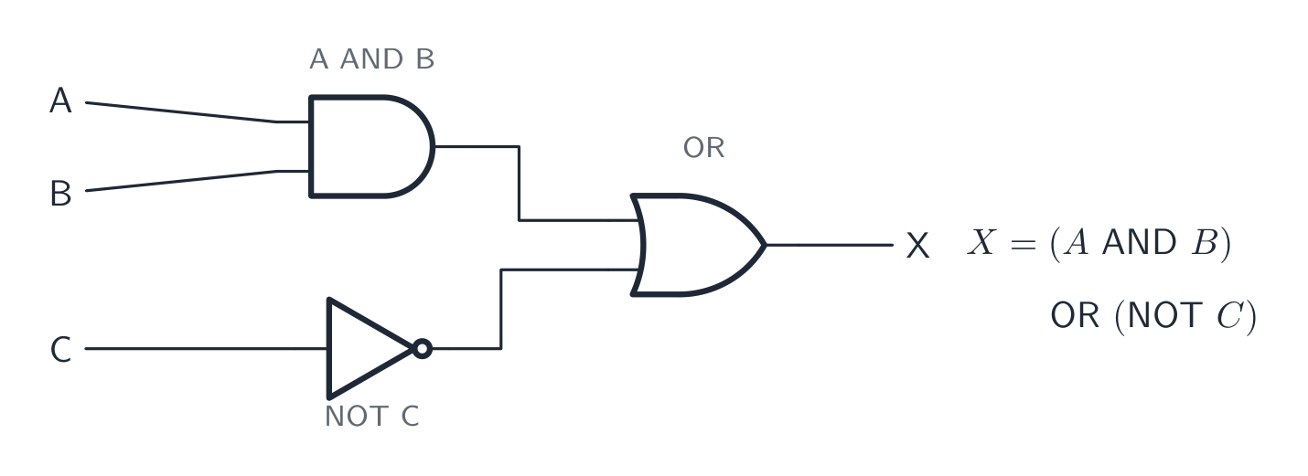
A logic expression 逻辑表达式 writes a circuit using letters and gate words. The usual way to write the gates:
| Gate | In words |
|---|---|
| NOT A | NOT A |
| A AND B | A AND B |
| A OR B | A OR B |
For example, the expression (A AND B) OR (NOT C) means: do A AND B, do NOT C, then OR the two results together.
Explore
Truth tables
Build the truth table for AND, OR, XOR and NOT — the logic behind every expression.
Vocabulary
Train
| English |
|---|
| logic expression/ˈlɒdʒɪk ekˈspreʃn/ |
10.4
Logic circuits

A logic circuit 逻辑电路 joins gates together to carry out a task. The output of one gate can become the input of another. At IGCSE a circuit has up to three inputs and one output.
You must be able to move between four forms:
- a problem statement 问题陈述 (a description in words),
- a logic expression,
- a logic circuit,
- a truth table.
From a problem statement to a circuit
Read the statement and pick out the conditions and the logic words (and, or, not). For example:
An alarm (X) sounds when the door is open (A) AND the system is switched on (B).
This is X = A AND B, so you draw one AND gate with inputs A and B.
Completing a truth table from a circuit or expression
To fill in a truth table:
- Write all the input combinations. For three inputs there are 8 rows (000 up to 111).
- Work out each gate's output in order, one column at a time.
- The last column is the final output.
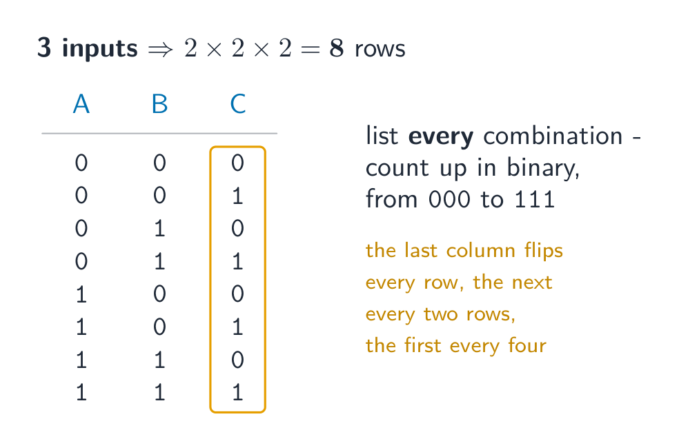
| A | B | C | A AND B | (A AND B) OR C |
|---|---|---|---|---|
| 0 | 0 | 0 | 0 | 0 |
| 0 | 0 | 1 | 0 | 1 |
| 0 | 1 | 0 | 0 | 0 |
| 0 | 1 | 1 | 0 | 1 |
| 1 | 0 | 0 | 0 | 0 |
| 1 | 0 | 1 | 0 | 1 |
| 1 | 1 | 0 | 1 | 1 |
| 1 | 1 | 1 | 1 | 1 |
Adding a middle "working" column for each gate makes the final output easy to fill in. Always draw the circuit exactly as the statement says, without simplifying it.
Worked example. Complete the truth table for X = (A AND B) OR (NOT C) for the row A = 1, B = 0, C = 0. Work outwards from the brackets, one gate at a time. First A AND B = 1 AND 0 = 0, because AND needs both inputs to be 1. Next NOT C = NOT 0 = 1. Finally OR the two results: 0 OR 1 = 1. So X = 1. Give each intermediate gate its own column rather than trying to do the whole expression in one step: with three inputs there are $2^3 = 8$ rows, and those intermediate columns are where the method marks live even if the final answer slips.
Vocabulary
Train
| English |
|---|
| logic circuit/ˈlɒdʒɪk ˈsɜːkɪt/ |
| problem statement/ˈprɒbləm ˈsteɪtmənt/ |
10.5
Exam tips
- Learn all six gates and their truth tables: NOT, AND, OR, NAND (NOT AND), NOR (NOT OR), XOR (output 1 when the inputs are different).
- Build a truth table with all input rows (2 inputs → 4 rows, 3 inputs → 8), counting up in binary, and add a working column for each gate.
- Turn a problem statement into a logic expression by picking out the AND / OR / NOT words, then draw it exactly as written — do not simplify it.
- NAND and NOR give the opposite output to AND and OR; a small circle on a gate's output means the result is inverted.
Interactive lessons on this topic
Work through it step by step, with instant-check exercises.