- understand and use the terms period, frequency and peak value as applied to an alternating current or voltage
- use equations of the form $x = x_0 \sin \omega t$ representing a sinusoidally alternating current or voltage
- recall and use the fact that the mean power in a resistive load is half the maximum power for a sinusoidal alternating current
- distinguish between root-mean-square (r.m.s.) and peak values and recall and use $I_{\text{r.m.s.}} = I_0 / \sqrt{2}$ and $V_{\text{r.m.s.}} = V_0 / \sqrt{2}$ for a sinusoidal alternating current
Alternating currents
A-Level Physics · Topic 21
 11:18
11:18
Alternating Current
The electricity in your wall is restless. Fifty times every second — sometimes sixty — it reverses direction, surging one way, then the other. This is…
English narration · English + 中文 subtitles burned in
21.1
Alternating current basics

Syllabus
Source: Cambridge International syllabus
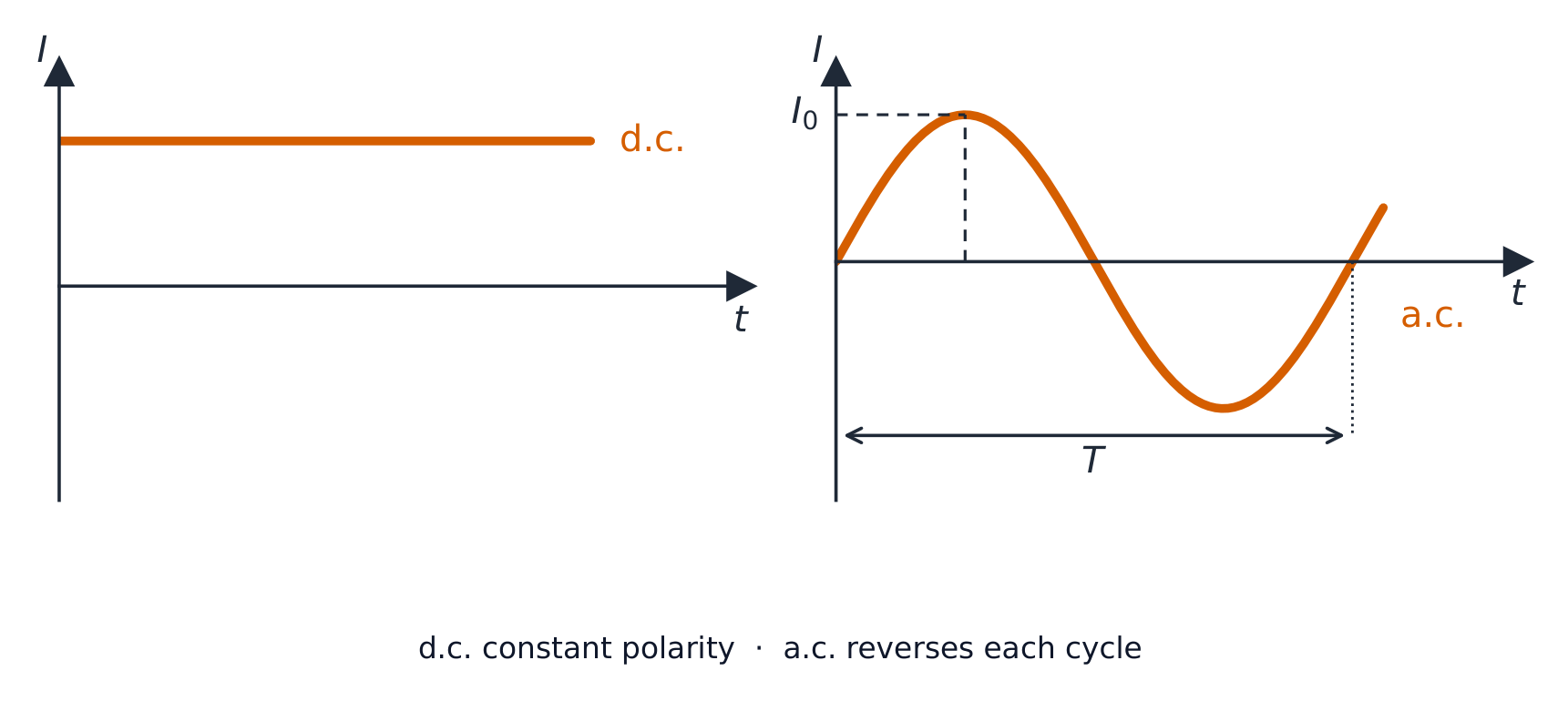
An alternating current 交流电 (a.c.) keeps reversing direction. Mains supply is sinusoidal a.c.: $I$ or $V$ follows a sine wave in time:
$$I = I_{0} \sin (\omega t), \qquad V = V_{0} \sin (\omega t).$$
(For a purely resistive load the voltage 电压 and current 电流 are in phase, which is the case in this syllabus.)
Key terms
- period 周期 $T$ — the time for one full cycle. Unit: s.
- frequency 频率 $f$ — cycles per second; $f = 1/T$. Mains is often $50\ \text{Hz}$ or $60\ \text{Hz}$.
- angular frequency 角频率 $\omega = 2\pi f = 2\pi/T$.
- peak value 峰值 $I_{0}$ or $V_{0}$ — the largest value in a cycle (also called the amplitude).
- peak-to-peak value 峰峰值 $2 I_{0}$ — from $+I_{0}$ to $-I_{0}$. Useful when reading an oscilloscope.
The two-mark definitions. The frequency of an alternating current is the number of complete cycles per unit time (say "per second" or "per unit time", and "complete cycles" or "oscillations"). The period is the time for one complete cycle, and the peak value is the maximum value of the current or voltage during a cycle. Note that the mean value of a sinusoidal current over a cycle is zero, which is exactly why the r.m.s. value is needed to describe it.
Reading the equation. In $V = V_{0} \sin(\omega t)$ the number in front is the peak value and the number multiplying $t$ is $\omega = 2\pi f$; the angle $\omega t$ is in radians 弧度, so set the calculator to radians before evaluating. A supply written with $\cos$ instead of $\sin$ is the same wave starting at its peak rather than at zero.
Worked example. The output of a supply is $V = 320 \sin(100\pi t)$ (volts, seconds). Find the peak value, the frequency, the period and the r.m.s. value, and the first time after $t = 0$ at which $V = 160\ \text{V}$.
Peak $V_{0} = 320\ \text{V}$. $\omega = 100\pi\ \text{rad s}^{-1}$, so $f = \omega/2\pi = 50\ \text{Hz}$ and $T = 1/f = 0.020\ \text{s}$. $V_{\text{r.m.s.}} = 320/\sqrt{2} = 226\ \text{V}$. For $V = 160\ \text{V}$: $\sin(100\pi t) = 0.5$, so $100\pi t = \pi/6$ and $t = 1/600 = 1.7 \times 10^{-3}\ \text{s}$. (For $V = 18\cos(40\pi t)$ the same reading gives $V_{0} = 18\ \text{V}$, $f = 20\ \text{Hz}$, $T = 50\ \text{ms}$, and a sketch that starts at $+18\ \text{V}$.)
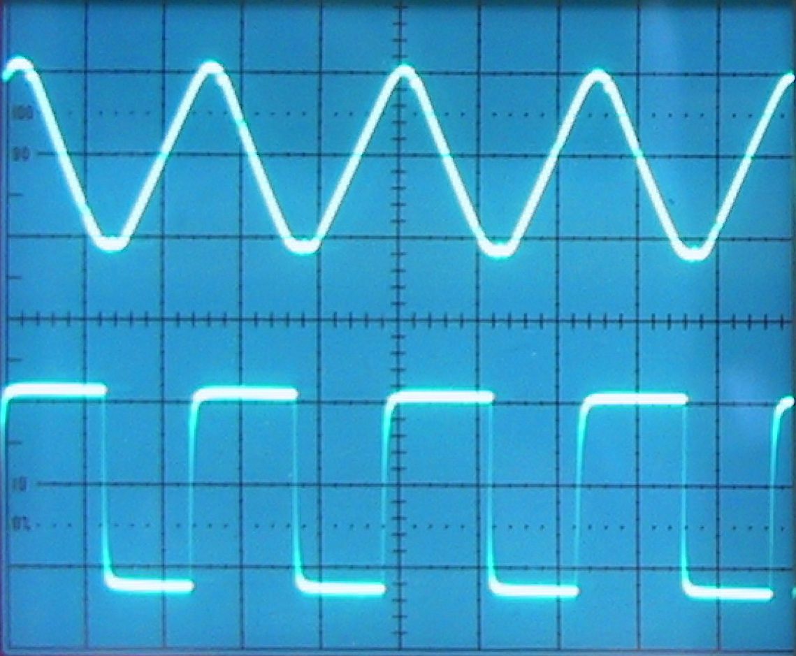
Reading a CRO trace
Same as for any wave (Topic 7), using a cathode-ray oscilloscope 示波器:
- horizontal divisions × time-base 时基 → period $T$, so $f = 1/T$.
- vertical divisions × $y$-gain → peak voltage $V_{0}$ (measure centre to peak, or peak-to-peak then halve).
Explore
Alternating current
I = a sin(bt)
AC is a sine wave — amplitude is the peak, b sets the frequency.
Vocabulary
Train
| English |
|---|
| alternating current/ˈɔːltəneɪtɪŋ ˈkʌrənt/ |
| current/ˈkʌrənt/ |
| voltage/ˈvəʊltɪdʒ/ |
| period/ˈpɪərɪəd/ |
| frequency/ˈfriːkwənsi/ |
| angular frequency/ˈæŋɡjʊlə ˈfriːkwənsi/ |
| peak value/piːk ˈvæljuː/ |
| peak-to-peak value/piːk tə piːk ˈvæljuː/ |
| radians/ˈreɪdɪənz/ |
| cathode-ray oscilloscope/ˈkæθəʊd reɪ ɒˈsɪləskəʊp/ |
| time-base/taɪm beɪs/ |
21.1
Power delivered to a resistor

For a resistive load $R$, the instant power 功率 is $P(t) = I(t)^{2} R$. With $I = I_{0}\sin(\omega t)$:
$$P(t) = I_{0}^{2} R \sin^{2}(\omega t).$$
This is always positive, with peak $I_{0}^{2} R$ and minimum zero, oscillating at twice the frequency of $I$. The mean of $\sin^{2}(\omega t)$ over a cycle is $\tfrac{1}{2}$, so the average power is
$$\langle P \rangle = \tfrac{1}{2} I_{0}^{2} R = \tfrac{1}{2} P_{\text{peak}}.$$
Average a.c. power in a resistor is half the peak power.
"Show by calculation that the mean power is half the peak power." A supply of peak value $12\ \text{V}$ drives a $680\ \Omega$ resistor. Peak power: $P_{0} = V_{0}^{2}/R = 12^{2}/680 = 0.212\ \text{W}$, the instantaneous power at the moment the voltage is at its peak. Mean power: use the r.m.s. value, $V_{\text{r.m.s.}} = 12/\sqrt{2} = 8.49\ \text{V}$, so $\langle P \rangle = V_{\text{r.m.s.}}^{2}/R = 8.49^{2}/680 = 0.106\ \text{W}$, exactly half. The two calculations must be shown separately; writing "$\tfrac{1}{2}$ of $0.212$" scores nothing, because that is the thing being shown. The $\tfrac{1}{2}$ is $(1/\sqrt{2})^{2}$: squaring the r.m.s. factor.
Vocabulary
Train
| English |
|---|
| power/ˈpaʊə/ |
21.1
Root-mean-square (r.m.s.) values

The r.m.s. current $I_{\text{r.m.s.}}$ is the steady direct current that would give the same average power in the same resistance 电阻 $R$. From $\langle P \rangle = I_{\text{r.m.s.}}^{2} R = \tfrac{1}{2} I_{0}^{2} R$:
$$I_{\text{r.m.s.}} = \frac{I_{0}}{\sqrt{2}}, \qquad V_{\text{r.m.s.}} = \frac{V_{0}}{\sqrt{2}}.$$
Worked example. An a.c. supply has a peak voltage of $12\ \text{V}$. Find its r.m.s. voltage.
$$V_{\text{r.m.s.}} = \frac{V_{0}}{\sqrt{2}} = \frac{12}{\sqrt{2}} \approx 8.5\ \text{V}.$$
The $\sqrt{2}$ comes from the name root-mean-square 均方根: $I_{\text{r.m.s.}} = \sqrt{\langle I^{2} \rangle}$ and $\langle \sin^{2}\rangle = \tfrac{1}{2}$. (Only the sinusoidal case is needed.)
The two-mark definition. The r.m.s. value of an alternating current is the value of the direct (steady) current that would dissipate the same (mean) power in the same resistor. "By reference to the heating effect" means exactly this sentence: same resistor, same power (or same heating), direct current. A definition that only says "$I_{0}/\sqrt{2}$" scores nothing, because that formula is true only for a sine wave.
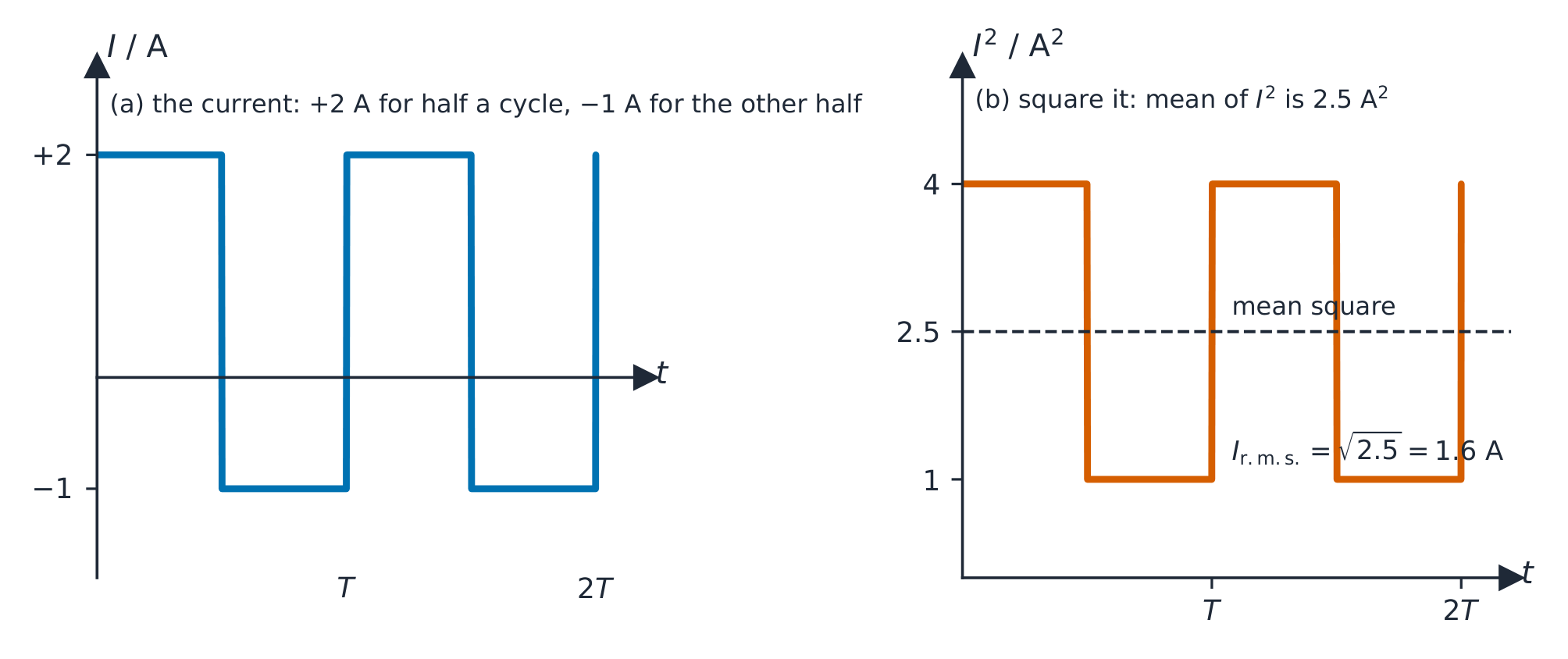
Worked example (non-sinusoidal). A current through a resistor is $+2.0\ \text{A}$ for the first half of each cycle and $-1.0\ \text{A}$ for the second half, a square wave 方波. Find its r.m.s. value and the mean power in a $10\ \Omega$ resistor.
Square the current: $4.0\ \text{A}^{2}$ for half the time and $1.0\ \text{A}^{2}$ for the other half, so the mean square is $(4.0 + 1.0)/2 = 2.5\ \text{A}^{2}$ and $I_{\text{r.m.s.}} = \sqrt{2.5} = 1.6\ \text{A}$. Mean power $= I_{\text{r.m.s.}}^{2} R = 2.5 \times 10 = 25\ \text{W}$. The sign of the current does not matter to the heating (it is squared away), and $I_{0}/\sqrt{2}$ would have given the wrong answer, $1.4\ \text{A}$: that shortcut is for sine waves only.
Why r.m.s. matters
Quoted a.c. values are r.m.s. values. "$230\ \text{V}$ mains" means $V_{\text{r.m.s.}} = 230\ \text{V}$, with peak $V_{0} = 230\sqrt{2} \approx 325\ \text{V}$. Components must be rated for the peak, not the r.m.s. Average power then takes the d.c. form:
$$\langle P \rangle = I_{\text{r.m.s.}}^{2} R = V_{\text{r.m.s.}}^{2} / R = V_{\text{r.m.s.}} I_{\text{r.m.s.}}.$$
Worked example. A heater of resistance $50\ \Omega$ is connected to the $230\ \text{V}$ r.m.s. mains. Find the r.m.s. current and the average power dissipated.
$$I_{\text{r.m.s.}} = \frac{V_{\text{r.m.s.}}}{R} = \frac{230}{50} = 4.6\ \text{A}, \qquad \langle P \rangle = V_{\text{r.m.s.}} I_{\text{r.m.s.}} = 230 \times 4.6 \approx 1.1 \times 10^{3}\ \text{W}.$$
Worked example. A sinusoidal supply of r.m.s. value $4.2\ \text{V}$ and frequency $50\ \text{kHz}$ is connected across a $150\ \Omega$ resistor. Find the peak current, the mean power, and write down an equation for the current.
$V_{0} = 4.2\sqrt{2} = 5.9\ \text{V}$, so $I_{0} = V_{0}/R = 5.9/150 = 0.040\ \text{A}$ (or $I_{\text{r.m.s.}} = 4.2/150 = 0.028\ \text{A}$ and then $\times\sqrt{2}$). Mean power $= V_{\text{r.m.s.}}^{2}/R = 4.2^{2}/150 = 0.12\ \text{W}$. With $\omega = 2\pi f = 2\pi \times 5.0 \times 10^{4} = 3.1 \times 10^{5}\ \text{rad s}^{-1}$: $I = 0.040 \sin(3.1 \times 10^{5} t)$ (amps, seconds). Keep the two families apart: peak values go into the equation and into component ratings; r.m.s. values go into power.
Vocabulary
Train
| English |
|---|
| root-mean-square/ruːt miːn skweə/ |
| resistance/rɪˈzɪstəns/ |
| square wave/skweə weɪv/ |
21.2
Rectification
Syllabus
- distinguish graphically between half-wave and full-wave rectification
- explain the use of a single diode for the half-wave rectification of an alternating current
- explain the use of four diodes (bridge rectifier) for the full-wave rectification of an alternating current
- analyse the effect of a single capacitor in smoothing, including the effect of the values of capacitance and the load resistance
Source: Cambridge International syllabus
Rectification 整流 turns an alternating voltage into a one-direction (d.c.-like) voltage, using diodes 二极管 (which conduct in only one direction).
"State what is meant by rectification." The conversion of an alternating current (or voltage) into a direct current (or voltage): one that flows in one direction only, however much it varies. A diode conducts only when it is forward-biased 正向偏置, that is, when its anode (the flat end of the symbol's triangle) is more positive than its cathode (the bar); otherwise it is reverse-biased and behaves like an open switch. Treat it as ideal: zero resistance one way, infinite the other.
Half-wave rectification
A single diode in series with the load passes only the positive half of each cycle; in the negative half the diode is reverse-biased 反向偏置 and no current flows. This is half-wave rectification 半波整流.
Output: positive half-waves with flat zero gaps. The mean output is $V_{0}/\pi \approx 0.32 V_{0}$. Drawback: half the input is wasted and the output is very uneven.

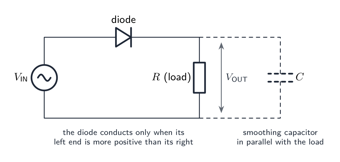
Completing the circuit. "Complete the diagram to produce half-wave rectification" needs one diode in series between the supply and the load, with the triangle pointing the way the output current must flow, and $V_{\text{OUT}}$ taken across the load. If a capacitor is to smooth the output it goes across the load (in parallel); a capacitor in series would block the d.c. altogether.
Full-wave rectification (bridge rectifier)
A bridge rectifier 桥式整流器 uses four diodes arranged so the current through the load always flows the same way, whichever a.c. terminal is positive — full-wave rectification 全波整流. On each half-cycle a different pair of diodes conducts, but the load always sees the same direction.

Explaining the bridge (the standard four-marker). When terminal P is positive, current leaves P, passes through the diode pointing away from P to the top of the load, flows down through the load and returns to Q through the diode pointing towards Q; the other two diodes are reverse-biased and carry nothing. When Q is positive the other pair conducts, but they are arranged so that the current still enters the load at the top: the load current is in the same direction in both half-cycles. Name the diodes in each half-cycle and say which end of the load is positive.
Completing a bridge. Given a bridge with diodes missing, remember the rule for every diode: conventional current flows through it in the direction of the triangle. Both diodes joined to the positive output terminal must point towards it; both joined to the negative output terminal must point away from it. A bridge with a diode the wrong way round either short-circuits the supply on one half-cycle or passes nothing.
Output: a continuous run of positive half-waves (no gaps), at twice the input frequency. The mean output is $2V_{0}/\pi \approx 0.64 V_{0}$ — double the half-wave value. It uses all the input and is smoother and easier to filter.

Drawing the diagrams
- half-wave: a.c. source — single diode — load $R$, in series.
- full-wave bridge: four diodes as the arms of a "diamond"; the a.c. input goes to one pair of opposite corners, the load $R$ across the other pair. The diode directions make the load terminals keep the same polarity for either input polarity.
"State the difference between half-wave and full-wave rectification." In half-wave rectification only one half of each input cycle appears at the output and the other half is blocked (the output is zero for half the time); in full-wave rectification both halves appear, one of them inverted, so there are no gaps and the output has twice the input frequency. A sketch should show, for half-wave, positive humps separated by flat zero sections of equal length; for full-wave, positive humps joined at the zero line.
Explore
Rectifier and smoothing route
Watch alternating input become a smoother direct output.
Vocabulary
Train
| English |
|---|
| rectification/ˌrektɪfɪˈkeɪʃn/ |
| diode/ˈdaɪəʊd/ |
| forward-biased/ˈfɔːwəd ˈbaɪəst/ |
| reverse-biased/rɪˈvɜːs ˈbaɪəst/ |
| half-wave rectification/hɑːf weɪv ˌrektɪfɪˈkeɪʃn/ |
| full-wave rectification/fʊl weɪv ˌrektɪfɪˈkeɪʃn/ |
| bridge rectifier/brɪdʒ ˈrektɪfaɪə/ |
21.2
Smoothing with a capacitor

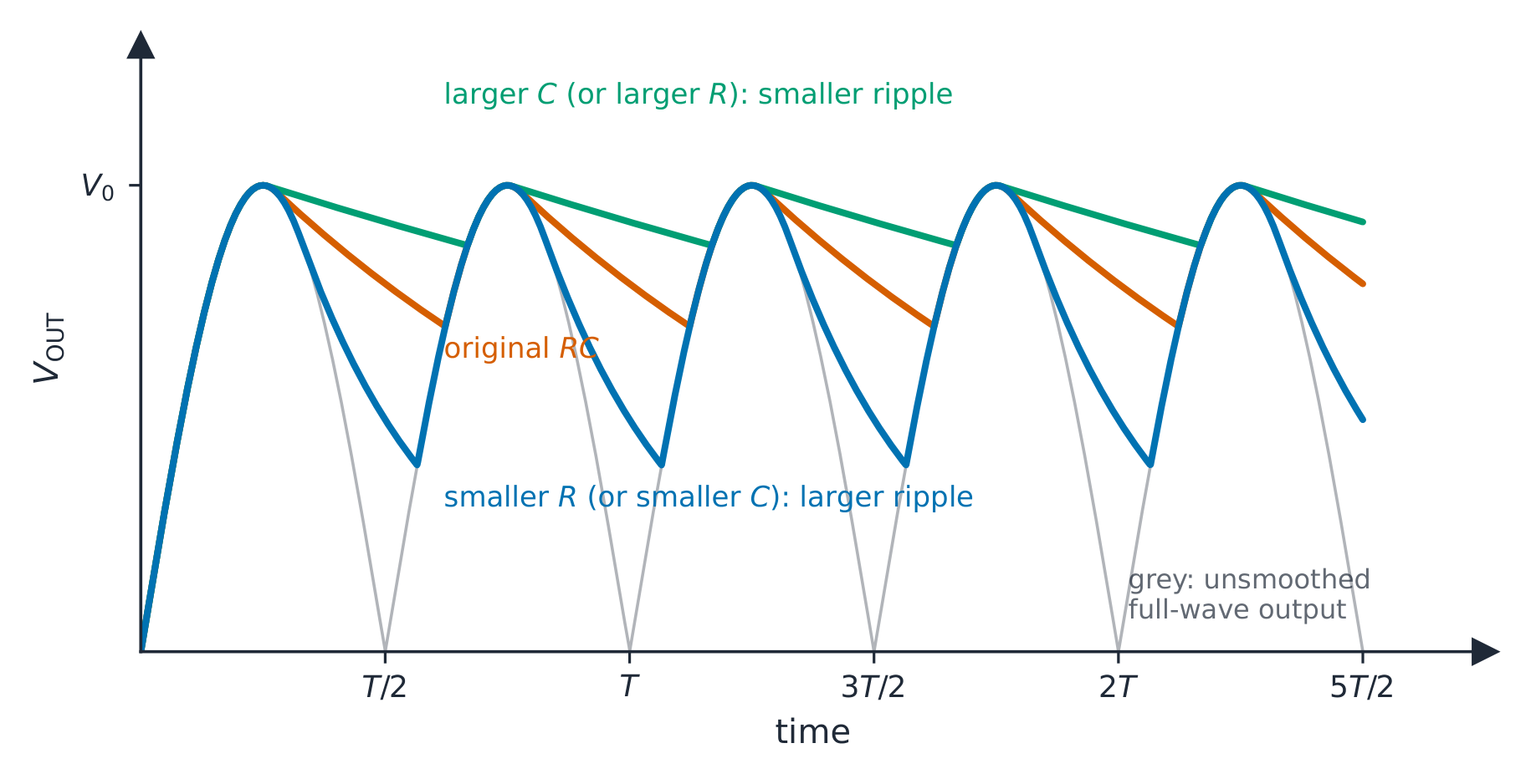
A rectifier's output is still bumpy. To smooth it, put a capacitor 电容器 $C$ in parallel with the load $R$.
How it works
- on the rising part of each pulse, the capacitor charges up to near the peak.
- on the falling part (and any gap), the diodes are reverse-biased, so the capacitor discharges through the load, keeping current flowing. The voltage falls with time constant 时间常数 $RC$ (Topic 19).
- at the next peak, the capacitor charges again, and the cycle repeats.
The output now sits near the peak with small dips. The size of the dips is the ripple 纹波 (this whole step is called smoothing 平滑).
Worked example. A half-wave rectifier fed from a $50\ \text{Hz}$ supply has a $470\ \mu\text{F}$ capacitor across its $1.2\ \text{k}\Omega$ load 负载. Estimate the fractional fall in the output between peaks, and say how it changes with a bridge rectifier.
The peaks are $T = 1/50 = 20\ \text{ms}$ apart (half-wave: one peak per cycle). The time constant is $RC = (1.2 \times 10^{3})(470 \times 10^{-6}) = 0.56\ \text{s}$. Between peaks the capacitor discharges to $V_{0} e^{-t/RC} = V_{0} e^{-0.020/0.56} = 0.965\,V_{0}$, a fall of about $3.5\%$. With full-wave rectification the peaks are $10\ \text{ms}$ apart, so the fall is only $1.8\%$; doubling the capacitance would halve it again. Because $t \ll RC$ the fall is approximately $V_{0}\, t/(RC)$: the ripple is proportional to the time between peaks and inversely proportional to both $R$ and $C$. (A network of capacitors across the output combines by the rules of Topic 19 before it is used here.)
What reduces the ripple
- larger $C$ → more stored charge → smaller dip between peaks → smaller ripple.
- larger $R$ → smaller load current → slower discharge → smaller ripple.
- higher rectified frequency (full-wave is twice the input) → less time to discharge between peaks → smaller ripple.
In short, a large $RC$ compared with the time between peaks gives a smoother output.
Sketching the smoothed output. Draw the unsmoothed humps faintly first. The smoothed curve touches each peak, then falls along a gentle curve (steepest just after the peak) until the next hump rises to meet it, where it turns sharply upwards and follows the hump to the peak. It never falls to zero, and it never rises above the peak. For half-wave rectification the decay has to last through the missing half-cycle as well, so the ripple is about twice that of full-wave for the same $RC$. If the question changes $C$ or $R$, redraw on the same axes: a larger $RC$ hugs the peak line more closely; a smaller $RC$ sags further.
Purpose in summary
The smoothing capacitor reduces the ripple, giving a steadier d.c. voltage suitable for sensitive electronics.
Vocabulary
Train
| English |
|---|
| load/ləʊd/ |
| smoothing/ˈsmuːðɪŋ/ |
| capacitor/kəˈpæsɪtə/ |
| time constant/taɪm ˈkɒnstənt/ |
| ripple/ˈrɪpl/ |
21.2
Definitions the examiner accepts
A definition question is marked against fixed wording. Learn these exactly, and give one answer only.
| Term | Definition |
|---|---|
| alternating current | a current that reverses its direction periodically (varies sinusoidally with time about zero) |
| period | the time for one complete cycle |
| frequency | the number of complete cycles per unit time |
| peak value | the maximum value of the current or voltage in a cycle |
| r.m.s. value | the value of the direct (steady) current that would dissipate the same power in the same resistor |
| rectification | the conversion of an alternating current into a direct (one-direction) current |
| half-wave rectification | only one half of each cycle is passed to the output; the other half is blocked |
| full-wave rectification | both halves of each cycle appear at the output in the same direction |
| smoothing | using a capacitor across the load to reduce the variation (ripple) of a rectified output |
21.2
Exam tips
- $V = V_{0} \sin\omega t$ with $\omega = 2\pi f$ in radians per second: read $V_{0}$ and $\omega$ straight off the equation; radian mode for any time calculation.
- $I_{\text{r.m.s.}} = I_{0}/\sqrt{2}$ and $V_{\text{r.m.s.}} = V_{0}/\sqrt{2}$ for a sine wave only; otherwise square, average, root. Quoted mains values are r.m.s.; components are rated for the peak.
- Mean power in a resistor is $I_{\text{r.m.s.}}^{2}R = V_{\text{r.m.s.}}^{2}/R = \tfrac{1}{2} I_{0}^{2} R$, half the peak power; the mean current is zero, the mean power is not.
- One diode in series gives half-wave rectification; a four-diode bridge gives full-wave, with the load current always in the same direction and the output at twice the input frequency.
- Smoothing: capacitor across the load; ripple falls with a larger $C$, a larger $R$ (smaller load current) and a higher rectified frequency, because the decay between peaks is $V_{0}e^{-t/RC}$.
- Sketches are marked on shape: humps that touch the peak line, a decay that never reaches zero, flat zero gaps for half-wave, none for full-wave.
Common mistakes
- Using the peak value in a power calculation, or the r.m.s. value as the amplitude in $V = V_{0}\sin\omega t$.
- Writing $\omega = f$ or $\omega = 2\pi/f$; it is $2\pi f = 2\pi/T$.
- Defining the r.m.s. value as "the peak divided by $\sqrt{2}$", or leaving out "same power" and "same resistor".
- Applying $I_{0}/\sqrt{2}$ to a square or triangular wave.
- Drawing a diode backwards, or a bridge in which two diodes joined to the same output terminal point opposite ways.
- Putting the smoothing capacitor in series with the load.
- A smoothed output sketched falling to zero between peaks, or rising above the peak.
- Saying a larger load resistance gives a larger ripple; a larger $R$ means a smaller current, a slower discharge and a smaller ripple.
- Stating that full-wave rectification gives a steady d.c.; without a capacitor it is a series of humps with a large ripple.
Interactive lessons on this topic
Work through it step by step, with instant-check exercises.