- recall and use the circuit symbols shown in section 6 of this syllabus
- draw and interpret circuit diagrams containing the circuit symbols shown in section 6 of this syllabus
- define and use the electromotive force (e.m.f.) of a source as energy transferred per unit charge in driving charge around a complete circuit
- distinguish between e.m.f. and potential difference (p.d.) in terms of energy considerations
- understand the effects of the internal resistance of a source of e.m.f. on the terminal potential difference
D.C. circuits
A-Level Physics · Topic 10
 20:35
20:35
Practical Circuits
Here is an old battery, and a voltmeter says it is still full: nine volts. Yet connect it to a bulb, and the bulb barely glows. How can a full battery be so…
English narration · English + 中文 subtitles burned in
10.1
Practical circuits

Syllabus
Source: Cambridge International syllabus
e.m.f. and p.d.
The electromotive force 电动势 (e.m.f.) $\varepsilon$ of a source is the energy 能量 given to each unit of charge by the source as it drives the charge around a full circuit. Unit: volt.
The potential difference 电势差 (p.d.) across a component is the energy changed from electrical to other forms by each unit of charge as it passes through that component.
Both are in volts; they differ in energy direction:
- e.m.f. — energy put into the circuit by the source (chemical → electrical in a battery, mechanical → electrical in a generator).
- p.d. — energy taken out of the electrical form (electrical → thermal in a resistor, → light in a lamp, → kinetic in a motor).
The examiner's wording is fixed. e.m.f. is "the energy transferred per unit charge by the source in driving charge round a complete circuit"; p.d. is "the energy transferred per unit charge from electrical to other forms". Both are energy per charge, so the volt is a joule per coulomb ($1\ \text{V} = 1\ \text{J C}^{-1}$). Statements that are always true of a source: the e.m.f. is the terminal p.d. when no current flows; the total energy it gives to a charge $Q$ is $\varepsilon Q$. The name is a trap: an electromotive "force" is not a force and is not measured in newtons.
Worked example. A cell of e.m.f. $\varepsilon$ and internal resistance $r$ drives a charge $Q$ round a circuit whose terminal p.d. is $V$. Compare the energy transferred by the cell with the energy dissipated outside it.
The cell transfers $\varepsilon Q$ in total; the external circuit receives $VQ$. Since $V = \varepsilon - Ir < \varepsilon$ whenever a current flows, $VQ < \varepsilon Q$ — the difference $(\varepsilon - V)Q = IrQ$ is the energy turned to heat inside the cell.
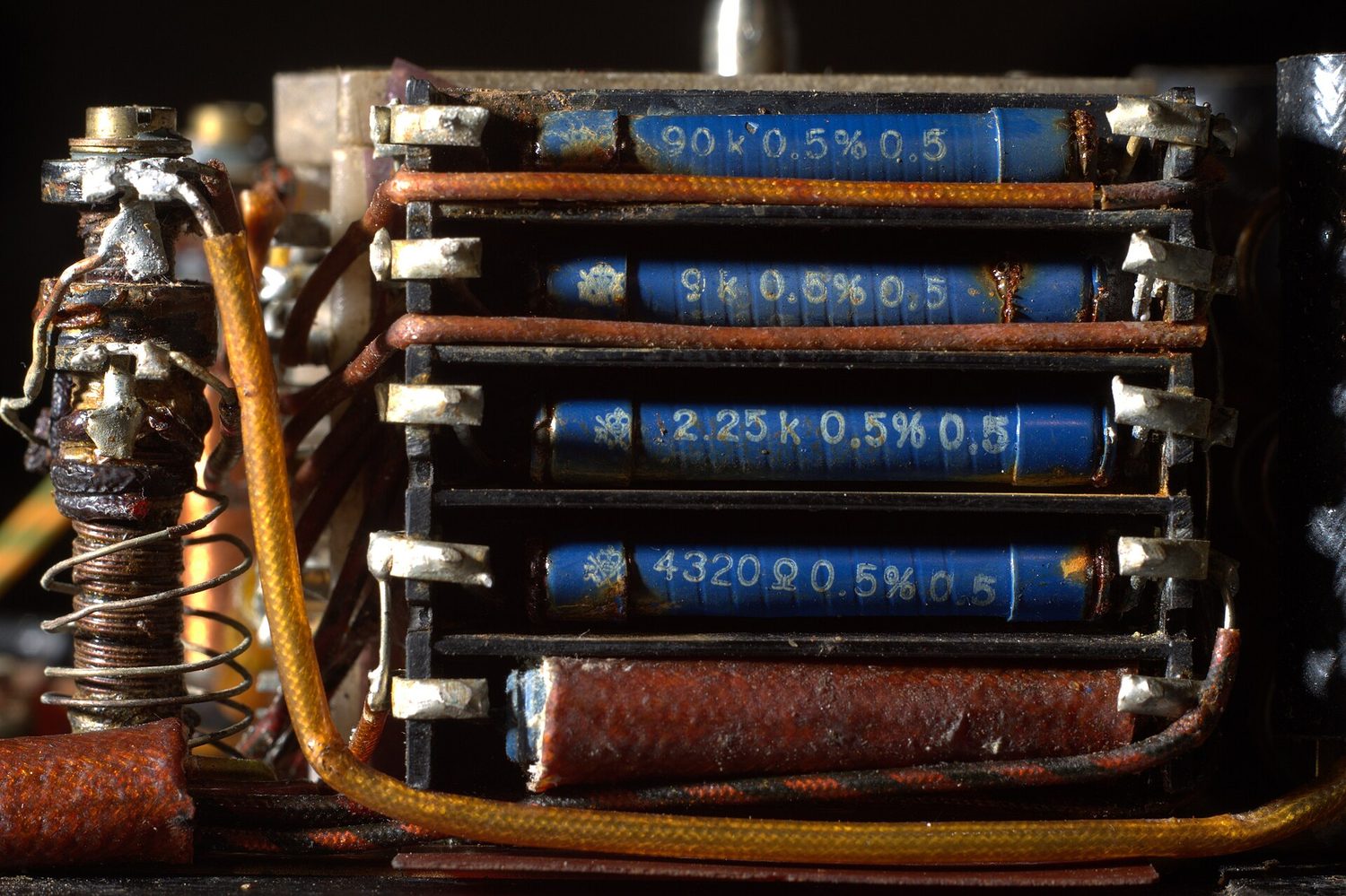
In the lab you often build a circuit on a breadboard 面包板 (a board with rows of holes that connect components without soldering) and measure currents and p.d.s with a multimeter 万用表.

Internal resistance
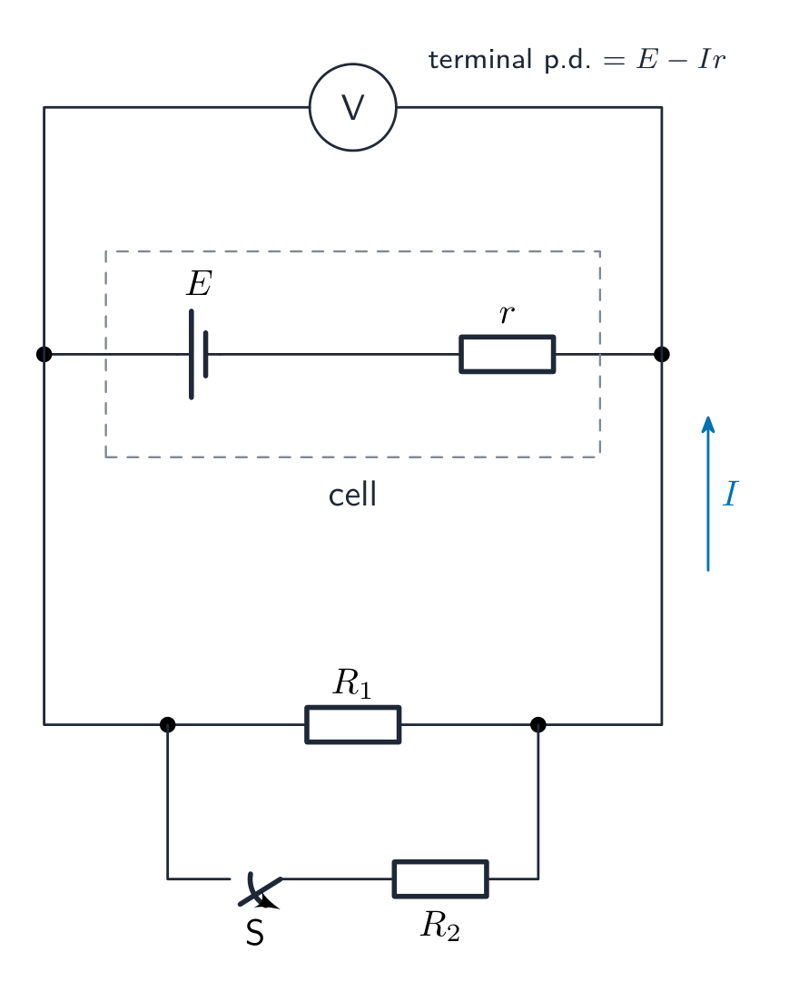
A real source has some internal resistance 内阻 $r$ — usually the resistance of the electrolyte 电解质 in a cell 电池, or the wire windings in a generator. When current $I$ flows, an internal p.d. of $Ir$ is "lost" inside the source, so the terminal p.d. 端电压 across the outside circuit is
$$V_{\text{terminal}} = \varepsilon - I r.$$
So:
- no current (open circuit 开路, $I = 0$): the terminal p.d. equals the e.m.f.
- larger current: the terminal p.d. falls.
- short circuit 短路 ($R_{\text{external}} \to 0$): $I = \varepsilon / r$, a large current, with all the energy turned to heat inside the source.
To measure $r$, change the outside resistance and plot $V_{\text{terminal}}$ against $I$: the line has $y$-intercept $\varepsilon$ and gradient $-r$.
Worked example. A cell of e.m.f. $1.5\ \text{V}$ and internal resistance $0.50\ \Omega$ is connected to a $2.5\ \Omega$ resistor. Find the current and the terminal p.d.
The e.m.f. drives the current through both resistances: $I = \dfrac{\varepsilon}{R + r} = \dfrac{1.5}{2.5 + 0.50} = 0.50\ \text{A}$. Then
$$V_{\text{terminal}} = \varepsilon - Ir = 1.5 - 0.50 \times 0.50 = 1.25\ \text{V}.$$


The power 功率 given to the outside load is $P_{\text{ext}} = (\varepsilon - Ir) I$; the power lost inside is $P_{\text{int}} = I^{2} r$; the total power from the source is $\varepsilon I$.
The efficiency 效率 of the source is $\dfrac{P_{\text{ext}}}{\varepsilon I} = \dfrac{VI}{\varepsilon I} = \dfrac{V}{\varepsilon} = \dfrac{R}{R + r}$: a large load resistance wastes little energy inside the source.
Worked example. A cell of e.m.f. $2.0\ \text{V}$ and internal resistance $0.40\ \Omega$ drives a current of $1.5\ \text{A}$ through a wire. Show that the terminal p.d. is $1.4\ \text{V}$ and find the percentage efficiency with which the cell supplies power to the wire.
$V = \varepsilon - Ir = 2.0 - 1.5 \times 0.40 = 2.0 - 0.60 = 1.40\ \text{V}$. Power to the wire $= VI = 1.4 \times 1.5 = 2.1\ \text{W}$; total power from the cell $= \varepsilon I = 2.0 \times 1.5 = 3.0\ \text{W}$. Efficiency $= 2.1 / 3.0 = 0.70$, i.e. $70\%$. In a "show that" question, write every step and the unrounded value ($1.40\ \text{V}$) before the value you were given.
When the outside circuit changes, argue through the current. Closing a switch that adds a second resistor in parallel lowers the total external resistance, so the current in the cell rises, the internal "lost volts" $Ir$ rise, and the terminal p.d. $\varepsilon - Ir$ falls; the p.d. across the original resistor (which is the terminal p.d.) therefore falls, and so does its current, even though the cell's current rose. This chain — resistance → current in the cell → $Ir$ → terminal p.d. — is the model answer for almost every "state and explain the effect" question in this topic.
Cells joined together. In series, e.m.f.s add and internal resistances add: three cells of e.m.f. $\varepsilon$ and internal resistance $r$ give $3\varepsilon$ and $3r$. A cell connected the wrong way round subtracts its e.m.f. (ten $1.5\ \text{V}$ cells with one reversed give $8 \times 1.5 = 12\ \text{V}$). Identical cells in parallel give the same e.m.f. $\varepsilon$ with a smaller internal resistance $r/N$, so they can supply a larger current.
Circuit symbols
You must recognise and draw the standard symbols in the syllabus: cell, battery, switch, resistor, variable resistor, ammeter 电流表, voltmeter 电压表, lamp, diode (and LED 发光二极管), capacitor 电容器, inductor, thermistor, light-dependent resistor, fuse 保险丝, earth, junction. An ideal ammeter has zero resistance 电阻 and goes in series 串联. An ideal voltmeter has infinite resistance and goes in parallel 并联.

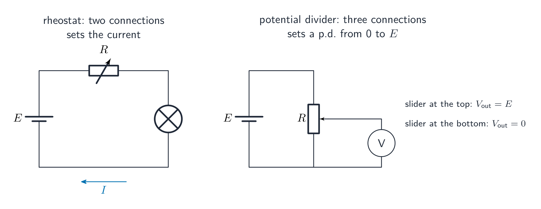
Drawing a circuit diagram. Marks are lost for symbols, not physics. Use ruler-straight lines and the standard symbols; an ammeter goes in series with the component whose current it measures and a voltmeter in parallel with (across) the component whose p.d. it measures; a cell with internal resistance is drawn as an ideal cell in series with a resistor $r$; and a variable resistor may be used in two ways, shown below. A "complete the circuit diagram" question usually wants exactly this measuring arrangement: source, ammeter and variable resistor in one series loop, voltmeter across the component under test.
Audio-device symbols
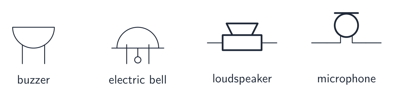
A buzzer and an electric bell turn electrical energy into sound; a loudspeaker turns a varying electrical signal into sound; a microphone turns sound into a varying electrical signal. Learn their distinct outlines and connections. The cup-shaped symbol with a flat top and two leads is the buzzer used in the AS examination; a device's function alone does not identify the symbol.
Explore
Internal resistance
V = ε − I·r
Terminal p.d. falls with current: it starts at the e.m.f. ε and drops by I·r.
Vocabulary
Train
| English |
|---|
| electromotive force/ɪˌlektrəʊˈməʊtɪv fɔːs/ |
| energy/ˈenədʒi/ |
| potential difference/pəˈtenʃl ˈdɪfrəns/ |
| breadboard/ˈbredbɔːd/ |
| multimeter/ˌmʌltɪˈmiːtə/ |
| internal resistance/ɪnˈtɜːnl rɪˈzɪstəns/ |
| electrolyte/ɪˈlektrəlaɪt/ |
| cell/sel/ |
| terminal p.d./ˈtɜːmɪnl ˌpiː ˈdiː/ |
| open circuit/ˈəʊpən ˈsɜːkɪt/ |
| short circuit/ʃɔːt ˈsɜːkɪt/ |
| power/ˈpaʊə/ |
| efficiency/ɪˈfɪʃənsi/ |
| ammeter/ˈæmiːtə/ |
| voltmeter/ˈvəʊltmiːtə/ |
| LED/ˌel iː ˈdiː/ |
| capacitor/kəˈpæsɪtə/ |
| fuse/fjuːz/ |
| resistance/rɪˈzɪstəns/ |
| series/ˈsɪəriːz/ |
| parallel/ˈpærəlel/ |
| loop/luːp/ |
10.2
Kirchhoff's laws

Syllabus
- recall Kirchhoff's first law and understand that it is a consequence of conservation of charge
- recall Kirchhoff's second law and understand that it is a consequence of conservation of energy
- derive, using Kirchhoff's laws, a formula for the combined resistance of two or more resistors in series
- use the formula for the combined resistance of two or more resistors in series
- derive, using Kirchhoff's laws, a formula for the combined resistance of two or more resistors in parallel
- use the formula for the combined resistance of two or more resistors in parallel
- use Kirchhoff's laws to solve simple circuit problems
Source: Cambridge International syllabus
First law (junction rule)
At any junction 节点, the total current flowing in equals the total current flowing out. This follows from conservation of charge 电荷守恒 — charge cannot build up at a point in a steady circuit, so charge in per second equals charge out per second.
For a junction with three wires: $I_{1} = I_{2} + I_{3}$ if currents 2 and 3 flow out and current 1 flows in.
Two ways the examiner asks it: "state the law" (one mark: the sum of the currents into a junction equals the sum of the currents out of it) and "state the conservation law behind it" (charge). Do not answer "energy" for the first law or "charge" for the second — the pairing is tested in almost every Paper 1.
Second law (loop rule)
Around any closed loop 回路, the total e.m.f. equals the total p.d. across the components in that loop. This follows from conservation of energy 能量守恒: as a unit of charge goes once round a loop, the energy it gains from sources equals the energy it gives up to components.
Pick a direction round the loop. Take an e.m.f. as positive when the loop direction goes from − to + of the source, and a p.d. as positive when the loop direction is the conventional current direction through the resistor.
In symbols, round any closed loop $\sum \varepsilon = \sum IR$. A source you pass from $+$ to $-$ counts as a negative e.m.f. (it is being charged, or opposes the other source), and a resistor you pass against its current counts as a negative p.d.
Worked example. Two batteries are in one loop with their e.m.f.s opposed: $12.0\ \text{V}$ with internal resistance $1.0\ \Omega$, and $8.0\ \text{V}$ with internal resistance $0.50\ \Omega$. Find the current.
Going round the loop, the net e.m.f. is $12.0 - 8.0 = 4.0\ \text{V}$ and the total resistance is $1.0 + 0.50 = 1.5\ \Omega$ (the internal resistances are in series), so $I = 4.0 / 1.5 = 2.7\ \text{A}$. The current flows in the direction driven by the larger e.m.f.
Combining resistors
Resistors in series. Derivation using Kirchhoff's laws: there is no junction between the resistors, so by the first law the same current $I$ passes through each. By the second law the e.m.f. round the loop equals the sum of the p.d.s:
$$\varepsilon = I R_{1} + I R_{2} + \ldots = I (R_{1} + R_{2} + \ldots),$$
so $R_{\text{series}} = R_{1} + R_{2} + \ldots$.

Resistors in parallel. Derivation: by the second law, each resistor forms its own loop with the source, so each has the same p.d. $V$ across it. By the first law the current entering the junction equals the sum of the branch currents:
$$I = \frac{V}{R_{1}} + \frac{V}{R_{2}} + \ldots = V \left(\frac{1}{R_{1}} + \frac{1}{R_{2}} + \ldots\right),$$
so $\dfrac{1}{R_{\text{parallel}}} = \dfrac{1}{R_{1}} + \dfrac{1}{R_{2}} + \ldots$.

Two equal resistors $R$ in parallel give $R/2$; $N$ equal ones give $R/N$. A parallel combination is always smaller than any of its resistors; a series combination is always larger.
Worked example. A $4.0\ \Omega$ resistor and a $12\ \Omega$ resistor are connected in parallel. Find their combined resistance.
$$\frac{1}{R} = \frac{1}{4.0} + \frac{1}{12} = \frac{3}{12} + \frac{1}{12} = \frac{4}{12} = \frac{1}{3} \quad\Rightarrow\quad R = 3.0\ \Omega.$$
Resistor networks and power
Reduce a mixed network one step at a time: replace each series chain by its sum and each parallel pair by $\dfrac{R_{1}R_{2}}{R_{1} + R_{2}}$ (the "product over sum" form, valid for two resistors only), redraw, and repeat until one resistor is left. Two rules decide which resistor dissipates the most power without any arithmetic: components carrying the same current dissipate more in the larger resistance ($P = I^{2}R$); components with the same p.d. dissipate more in the smaller resistance ($P = V^{2}/R$). In a series–parallel mix the single resistor that carries the whole current usually dissipates the most, because a parallel branch carries only a share of it.
Worked example. Three resistors, each of resistance $R$, are connected with two in series and that pair in parallel with the third. The total resistance between the ends is $8.0\ \Omega$. Find $R$.
The series pair is $2R$; in parallel with $R$: $R_{\text{T}} = \dfrac{2R \times R}{2R + R} = \dfrac{2R}{3}$. So $\dfrac{2R}{3} = 8.0$, giving $R = 12\ \Omega$. Check: the single resistor $R$ carries twice the current of the pair (same p.d., half the resistance), so it dissipates the most power.
Solving a circuit
- Label every current with a symbol and a chosen direction.
- Use Kirchhoff's first law 基尔霍夫第一定律 at each junction to link the currents.
- Use Kirchhoff's second law 基尔霍夫第二定律 around each loop to get equations in the p.d.s.
- Use $V = IR$ for each resistor.
- Solve the equations together.
For symmetric resistor networks, use the symmetry to spot branches with equal currents — the branch with the most current gives the most power ($P = I^{2}R$).
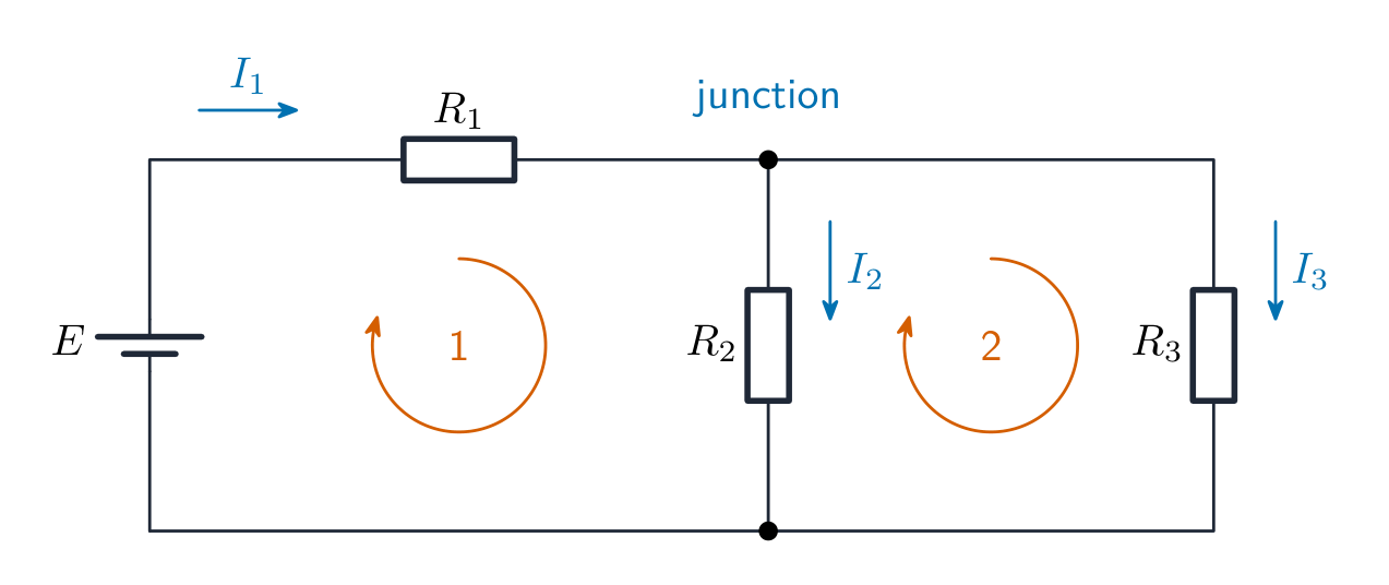
Worked example. In the circuit above $\varepsilon = 12\ \text{V}$ (negligible internal resistance), $R_{1} = 2.0\ \Omega$, $R_{2} = 6.0\ \Omega$ and $R_{3} = 3.0\ \Omega$. Find the three currents.
Kirchhoff's method. Junction: $I_{1} = I_{2} + I_{3}$. Loop 1 (through $\varepsilon$, $R_{1}$, $R_{2}$): $12 = 2.0 I_{1} + 6.0 I_{2}$. Loop 2 (through $R_{2}$ and $R_{3}$, no source): $0 = 6.0 I_{2} - 3.0 I_{3}$, so $I_{3} = 2 I_{2}$. Then $I_{1} = 3 I_{2}$ and $12 = 6.0 I_{2} + 6.0 I_{2}$, giving $I_{2} = 1.0\ \text{A}$, $I_{3} = 2.0\ \text{A}$ and $I_{1} = 3.0\ \text{A}$.
Reduction check. $6.0\ \Omega$ and $3.0\ \Omega$ in parallel give $2.0\ \Omega$; with $R_{1}$ the total is $4.0\ \Omega$, so $I_{1} = 12 / 4.0 = 3.0\ \text{A}$ and the p.d. across the parallel pair is $3.0 \times 2.0 = 6.0\ \text{V}$, giving $I_{2} = 6.0/6.0 = 1.0\ \text{A}$ and $I_{3} = 6.0/3.0 = 2.0\ \text{A}$. Both methods must agree; a negative answer for a current simply means you guessed its direction the wrong way.
Explore
Series & parallel circuits
Switch between series and parallel and add bulbs. In series they share the voltage and one break kills them all; in parallel each gets the full voltage and a break only loses its branch.
Vocabulary
Train
| English |
|---|
| junction/ˈdʒʌŋkʃn/ |
| conservation of charge/ˌkɒnsəˈveɪʃn ɒv tʃɑːdʒ/ |
| closed loop/kləʊzd luːp/ |
| conservation of energy/ˌkɒnsəˈveɪʃn ɒv ˈenədʒi/ |
| Kirchhoff's first law/ˈkɜːkhɒfs fɜːst lɔː/ |
| Kirchhoff's second law/ˈkɜːkhɒfs ˈsekənd lɔː/ |
10.3
Potential dividers

Syllabus
- understand the principle of a potential divider circuit
- recall and use the principle of the potentiometer as a means of comparing potential differences
- understand the use of a galvanometer in null methods
- explain the use of thermistors and light-dependent resistors in potential dividers to provide a potential difference that is dependent on temperature and light intensity
Source: Cambridge International syllabus
A potential divider 分压器 is two (or more) resistors in series across a source. The p.d. across each resistor is in direct proportion to its resistance:
$$V_{1} = V_{\text{in}} \cdot \frac{R_{1}}{R_{1} + R_{2}}, \qquad V_{2} = V_{\text{in}} \cdot \frac{R_{2}}{R_{1} + R_{2}}.$$
The output (tapped between $R_{1}$ and $R_{2}$) can be set to any voltage 电压 between $0$ and $V_{\text{in}}$ by choosing the resistances. A potentiometer 电位差计 used with all three of its connections (a slider on a uniform-resistance track) gives a smoothly variable divider; the same component with only two connections is a rheostat 变阻器, which just changes the current.
Worked example. A $6.0\ \text{V}$ supply is connected across a $2.0\ \text{k}\Omega$ resistor in series with a $4.0\ \text{k}\Omega$ resistor. Find the output voltage tapped across the $4.0\ \text{k}\Omega$ resistor.
$$V_{2} = V_{\text{in}} \cdot \frac{R_{2}}{R_{1} + R_{2}} = 6.0 \times \frac{4.0}{2.0 + 4.0} = 4.0\ \text{V}.$$
The same answer comes from the current-first route the mark scheme often lays out: $I = V_{\text{in}} / (R_{1} + R_{2}) = 6.0 / 6000 = 1.0\ \text{mA}$, then $V_{2} = I R_{2} = 1.0 \times 10^{-3} \times 4000 = 4.0\ \text{V}$. Two consequences worth remembering: the larger resistance takes the larger share of the p.d.; and the ratio formula holds only while no current is drawn from the output — a load (or a low-resistance voltmeter) in parallel with $R_{2}$ lowers the effective resistance of $R_{2}$ and so lowers $V_{2}$.
Sensor circuits
Replace one fixed resistor with a sensor 传感器 whose resistance changes with a physical quantity:
- thermistor 热敏电阻 (NTC): $R$ falls as temperature rises. In a divider, the output voltage changes with temperature in a fixed direction.
- light-dependent resistor 光敏电阻 (LDR): $R$ falls as light intensity 光强 rises, giving a brightness-dependent output.
Connect the output to a transistor 晶体管 base or a comparator 比较器 to switch a load on or off when the temperature or light passes a threshold 阈值.

Which way does the output go? The output can be taken across the sensor or across the fixed resistor, and the two choices respond in opposite directions. Argue through the current, in this order, and you have the full three-mark answer:
- the light gets brighter (or the temperature rises), so the resistance of the LDR (or thermistor) falls;
- the total resistance of the series circuit falls, so the current rises ($I = \varepsilon / R_{\text{total}}$);
- the p.d. across the fixed resistor $= IR$ rises, so the p.d. across the sensor $= \varepsilon - IR$ falls.
So an output across the fixed resistor rises with light or temperature; an output across the sensor falls. If the source has internal resistance, add one more link: the larger current also increases $Ir$, so the terminal p.d. falls slightly.
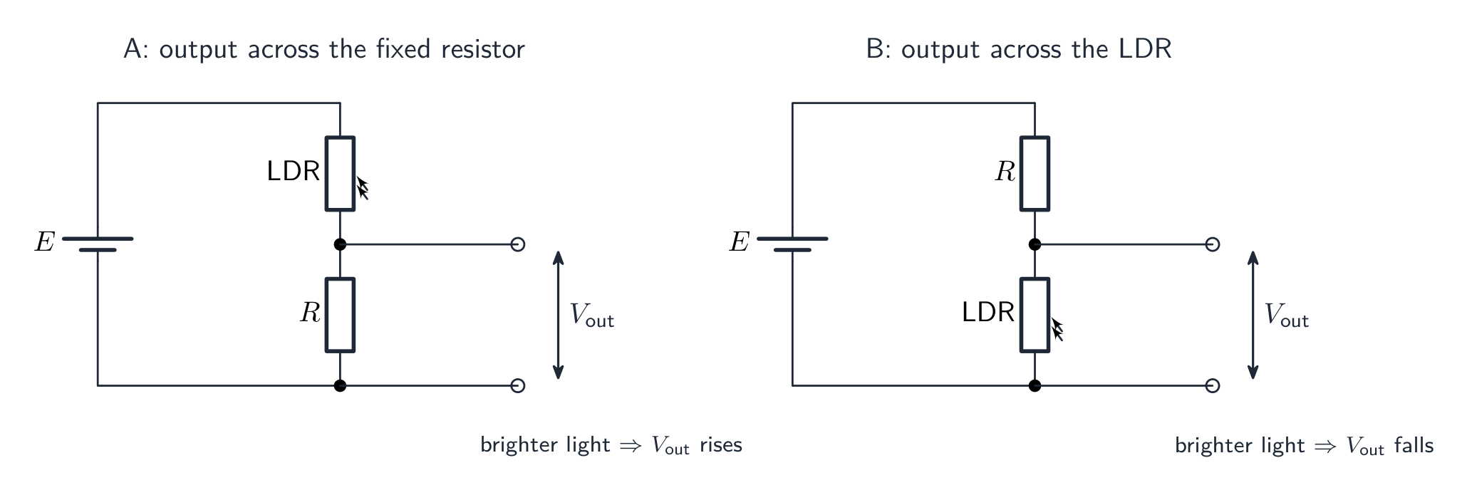
Worked example. A battery of e.m.f. $9.0\ \text{V}$ and negligible internal resistance is connected in series with an LDR and a $1200\ \Omega$ resistor. In the light the LDR has a resistance of $1800\ \Omega$. Calculate the p.d. across the LDR, and state and explain what happens to it when the light intensity decreases.
$V_{\text{LDR}} = 9.0 \times \dfrac{1800}{1800 + 1200} = 5.4\ \text{V}$. Less light → the resistance of the LDR increases → the total resistance increases and the current decreases → the p.d. across the $1200\ \Omega$ resistor ($IR$) decreases → the p.d. across the LDR ($9.0 - IR$) increases.
Worked example. A thermistor in series with a $5800\ \Omega$ resistor across a $6.0\ \text{V}$ supply gives a p.d. of $2.9\ \text{V}$ across the resistor. Find the resistance of the thermistor.
Current $= 2.9 / 5800 = 5.0 \times 10^{-4}\ \text{A}$. The thermistor takes the remaining $6.0 - 2.9 = 3.1\ \text{V}$, so $R = 3.1 / (5.0 \times 10^{-4}) = 6200\ \Omega$ (or, by ratio, $R = 5800 \times 3.1/2.9$).
Potentiometer and the null method
A potentiometer is a uniform resistance wire of length $L_{0}$ with a sliding contact (jockey 滑动触头). The resistance per unit length is uniform, so the p.d. from one end to the jockey is proportional to the length:
$$V_{x} = V_{\text{full}} \cdot \frac{x}{L_{0}}.$$
To compare two e.m.f.s (an unknown cell against a standard cell), connect each in turn with the jockey through a galvanometer 检流计. Slide the jockey until the galvanometer reads zero (a null — no current flows through the cell being measured, because the potentiometer's voltage there exactly opposes the cell's e.m.f.). The balance length 平衡长度 — the wire length from the end to the jockey at balance — is proportional to the e.m.f. being measured, so the two lengths are in the ratio of the e.m.f.s:
$$\frac{\varepsilon_{1}}{\varepsilon_{2}} = \frac{l_{1}}{l_{2}}.$$
This is a null method 零点法: you find the balance (zero current) instead of measuring a current's value. Its advantage is that at balance the unknown cell gives no current, so its internal resistance does not affect the result.

Why the null method is better than a voltmeter. At balance no current is drawn from the cell being measured, so there is no $Ir$ drop inside it: the balance point measures the e.m.f., not the terminal p.d. A voltmeter always draws some current, so it reads slightly less than the e.m.f.
Reading the balance point. The p.d. per unit length of the wire is fixed by the driver cell 驱动电池 and the resistance of the wire. Anything that makes the p.d. being balanced larger moves the balance point further along the wire; anything that makes the p.d. per unit length larger (a driver cell of larger e.m.f., or a wire that takes a larger share of the driver's p.d.) makes the balance length shorter. Replacing the wire by one of the same length but greater diameter lowers its resistance ($R = \rho L / A$): if the driver cell has negligible internal resistance and nothing else is in series, the p.d. across the wire is still the full e.m.f. and the balance length does not move; if the driver has internal resistance or a series resistor, the wire's share of the e.m.f. falls, the p.d. per metre falls, and the balance length grows. Say which case you are in.
Worked example. A potentiometer wire XY of length $2.0\ \text{m}$ carries a p.d. of $1.50\ \text{V}$. A cell of e.m.f. $E$ is balanced when the jockey is $1.6\ \text{m}$ from X. Find $E$, and state what happens to the balance length if the driver cell is replaced by one of larger e.m.f.
$E = 1.50 \times \dfrac{1.6}{2.0} = 1.2\ \text{V}$. A larger driver e.m.f. gives a larger p.d. per metre, so the same $1.2\ \text{V}$ is reached at a shorter length: the jockey must move towards X.
Explore
Sharing voltage in series
In a series loop the same current flows everywhere and the cell's voltage splits across the components — that split is how a potential divider works.
Vocabulary
Train
| English |
|---|
| potential divider/pəˈtenʃl dɪˈvaɪdə/ |
| voltage/ˈvəʊltɪdʒ/ |
| potentiometer/pəˌtentɪˈɒmɪtə/ |
| rheostat/ˈriːəstæt/ |
| sensor/ˈsensə/ |
| thermistor/ˈθɜːmɪstə/ |
| light-dependent resistor/laɪt dɪˈpendənt rɪˈzɪstə/ |
| light intensity/laɪt ɪnˈtensɪti/ |
| transistor/trænˈzɪstə/ |
| comparator/kəmˈpæreɪtə/ |
| threshold/ˈθreʃəʊld/ |
| jockey/ˈdʒɒki/ |
| galvanometer/ˌɡælvəˈnɒmɪtə/ |
| balance length/ˈbæləns leŋθ/ |
| null method/nʌl ˈmeθəd/ |
| driver cell/ˈdraɪvə sel/ |
10.3
Definitions the examiner accepts
A definition question is marked against fixed wording. Learn these exactly, and give one answer only.
| Term | Definition |
|---|---|
| electromotive force (e.m.f.) | the energy transferred per unit charge by a source in driving charge round a complete circuit |
| potential difference (p.d.) | the energy transferred per unit charge from electrical energy to other forms of energy |
| internal resistance | the resistance to current inside a source of e.m.f., which causes a p.d. $Ir$ across the source when a current flows |
| terminal p.d. | the p.d. across the terminals of a source, equal to e.m.f. $- Ir$ |
| Kirchhoff's first law | the sum of the currents into a junction is equal to the sum of the currents out of the junction (conservation of charge) |
| Kirchhoff's second law | the sum of the e.m.f.s round a closed loop is equal to the sum of the p.d.s round the loop (conservation of energy) |
| potential divider | two or more resistors in series across a supply, giving a p.d. across one of them that is a fraction of the supply p.d. |
| potentiometer | a uniform resistance wire with a sliding contact, used to compare p.d.s by finding the length at which a galvanometer reads zero |
| null method | a measurement made by adjusting a circuit until a meter reads zero, so no current is drawn from the component being measured |
| balance length | the length of potentiometer wire between one end and the sliding contact when the galvanometer reads zero |
10.3
Exam tips
- Apply Kirchhoff's laws: current into a junction $=$ current out (charge conserved); $\sum \text{e.m.f.} = \sum \text{p.d.}$ round a loop (energy conserved). Name the law you are using when a question says "use Kirchhoff's laws".
- Combine resistors: series $R = R_1 + R_2$; parallel $1/R = 1/R_1 + 1/R_2$. A parallel combination is always smaller than its smallest resistor.
- A potential divider splits voltage in the ratio of the resistances; the larger resistance takes the larger p.d.
- Include internal resistance: $\text{e.m.f.} = I(R + r)$ — the "lost volts" are $Ir$. When a circuit changes, argue resistance → current in the cell → $Ir$ → terminal p.d.
- "Negligible internal resistance" means the terminal p.d. is the e.m.f., whatever the current. Look for the phrase before you start.
- Read a $V$–$I$ graph of a source as $V = \varepsilon - Ir$: intercept $\varepsilon$, gradient $-r$, and the current at $V = 0$ is the maximum (short-circuit) current $\varepsilon / r$.
- In Paper 5, rearrange the circuit relation into $y = mx + c$ before plotting: a cell of e.m.f. $\varepsilon$ and internal resistance $r$ feeding $n$ equal resistors $R$ in parallel obeys $\varepsilon = I\left(\dfrac{R}{n} + r\right)$, so $\dfrac{1}{I} = \dfrac{R}{\varepsilon} \cdot \dfrac{1}{n} + \dfrac{r}{\varepsilon}$ — a graph of $1/I$ against $1/n$ has gradient $R/\varepsilon$ and intercept $r/\varepsilon$.
Common mistakes
- Writing $V = IR$ with the e.m.f. and the external resistance only, forgetting $r$. Use $\varepsilon = I(R + r)$.
- Saying e.m.f. is "the force that pushes the charge". It is energy per unit charge; the volt is a joule per coulomb.
- Pairing the laws with the wrong conservation law. First law — charge; second law — energy.
- Using "product over sum" for three parallel resistors. It works for two only; otherwise add the reciprocals.
- Explaining a sensor circuit by "the resistance changes so the voltage changes". The marks are for the chain: resistance → total resistance → current → $IR$ across the fixed resistor → the rest across the sensor.
- Claiming a potentiometer at balance "draws no current from the driver cell". It draws none from the cell being measured; the driver cell always supplies the wire current.
- Rounding a "show that" value before the last line — write $1.40\ \text{V}$, then say it is $1.4\ \text{V}$.
Interactive lessons on this topic
Work through it step by step, with instant-check exercises.