Fields, motors and induction
Introduit| English | Sens |
|---|---|
| induction/ɪnˈdʌkʃn/ | induction électromagnétique |
| transformer/trænsˈfɔːmə/ | transformateur |
What would explain this observation?
- A magnet beside a wire does not always produce a current. An induced electromotive force depends on changing magnetic flux linkage.
Build the model
- A field describes a force effect at positions in space.
- A current-carrying conductor in a magnetic field can experience a force.
- Electromagnetic induction 电磁感应 occurs when magnetic flux linkage changes.
- induction: Creation of emf by changing flux linkage.
- transformer 变压器: A device transferring energy between coils through changing flux.

Which gives a continuing emf in a coil?
Difficulté 1/5 · 100 pièces + un petit bonus lors de la première réussite aujourd'hui
Electromagnetic induction needs CHANGE: an emf is induced only while the flux linkage through the coil is changing. A constant flux, however large, induces nothing, and a stationary magnet beside a stationary coil changes no flux.
Match each technical term to its precise meaning.
Difficulté 2/5 · 140 pièces + un petit bonus lors de la première réussite aujourd'hui
Use the definitions to distinguish related quantities and processes.
Choose evidence that can test it
- Changing field strength, coil area, orientation or relative motion can change flux linkage.
- Lenz law describes an induced effect opposing the change producing it, consistent with energy conservation.
In the lab: Use a coil and sensitive meter to compare magnet motion in each direction. Record that a stationary arrangement gives no induced signal. Use approved low-voltage supplies for motor demonstrations.
Which two habits make the investigation or model in this case more defensible?
Difficulté 2/5 · 140 pièces + un petit bonus lors de la première réussite aujourd'hui
Stating the conditions and assumptions lets others repeat the work exactly, and recording the supporting evidence lets them check the conclusion. Hiding disagreeing results removes the evidence that could challenge a wrong conclusion, and one measurement can never establish a wider claim.
Work from known quantities
- Known: a transformer has 200 primary turns, 50 secondary turns and 12 V primary voltage.
- For an ideal transformer, Vs/Vp = Ns/Np.
- Vs = Vp Ns/Np = 12×50/200 = 3.0 V.
- Real transformers also dissipate energy.
Your turn: An ideal transformer has Np=400, Ns=100 and Vp=20 V. Find Vs.
Turns set the AC voltage ratio
Fewer secondary turns reduce voltage; more secondary turns increase it.
An ideal transformer has Np=400, Ns=100 and Vp=20 V. Find Vs.
Difficulté 2/5 · 140 pièces + un petit bonus lors de la première réussite aujourd'hui
The result is 5 V. Known: Np = 400, Ns = 100, Vp = 20 V, ideal transformer. Use Vs/Vp = Ns/Np. Rearranging: Vs = Vp x Ns/Np = 20 x 100/400 = 5 V. Fewer secondary turns step the voltage down.
Check the conclusion and its limits
- A transformer needs changing magnetic flux; a steady DC input does not provide continuous transformer action.
- Magnetic field direction is not automatically the direction of force.
Not true: A steady DC input produces continuous ideal transformer action. A transformer works by electromagnetic induction, which requires changing flux. A steady primary current gives constant flux and no continuing secondary emf. Switching can induce a transient. A fixed DC voltage on an ideal zero-resistance winding is a different limit and does not describe normal steady transformer operation.
- A field describes a force effect at positions in space.
- Changing field strength, coil area, orientation or relative motion can change flux linkage.
- Watch for: A transformer needs changing magnetic flux; a steady DC input does not provide continuous transformer action.
A steady DC input produces continuous ideal transformer action.
Difficulté 1/5 · 100 pièces + un petit bonus lors de la première réussite aujourd'hui
A transformer works by electromagnetic induction, which requires changing flux. A steady primary current gives constant flux and no continuing secondary emf. Switching can induce a transient. A fixed DC voltage on an ideal zero-resistance winding is a different limit and does not describe normal steady transformer operation.
Creation of emf by changing flux linkage: write the technical term.
Difficulté 1/5 · 100 pièces + un petit bonus lors de la première réussite aujourd'hui
induction means Creation of emf by changing flux linkage.
Write from the data: find the secondary voltage
- An ideal transformer has 250 primary turns, 100 secondary turns and an alternating primary voltage of 20 V rms.
- Find the secondary rms voltage. Explain why a steady primary current would not sustain a secondary emf.
An ideal transformer has 250 primary turns, 100 secondary turns and an alternating primary voltage of 20 V rms. What is the secondary rms voltage, and why would a steady primary current not sustain a secondary emf?
Vs/Vp = Ns/Np, so Vs = 20 × (100/250) = 8 V rms. Both voltage values must use the same measure. Induction needs changing flux; steady primary current gives none, while switching can give a transient.
An ideal transformer has 250 primary turns and 100 secondary turns. With an alternating primary voltage of 20 V, what is the secondary voltage?
Difficulté 1/5 · 100 pièces + un petit bonus lors de la première réussite aujourd'hui
20 times 100 divided by 250 is 8 V. Other options — 5 V (the lesson example's result for 400 primary turns, 100 secondary turns and 20 V); 20 V (the primary voltage).
AHL: distinguish an induced emf from current
- A wireless charging pad drives a changing current through a coil. Its changing magnetic field links another coil in the phone, inducing an emf. Electronic circuits supply and control the changing input and convert the received output for charging. The gap does not mean energy appears without a source: the electrical input supplies it. Coupling, alignment and losses affect how much reaches the phone.
- An induced emf is an energy transfer per unit charge around a circuit. It can exist even when a gap prevents a sustained current. Closing a resistive circuit allows current; the current then depends on total resistance and, during rapid changes, self-induction. First decide whether the question asks for emf, current, or energy. A stationary strong magnet next to a stationary coil does not induce a continuing emf if the linked flux is constant.
A changing flux links an open coil. Which statement is justified?
Difficulté 1/5 · 100 pièces + un petit bonus lors de la première réussite aujourd'hui
Induction establishes an emf. A sustained resistive loop current additionally requires a complete path and depends on total resistance and any inductive transient.
AHL: measure flux using the normal
- For a flat area in a uniform magnetic field, flux is $\Phi=BA\cos\theta$, where $\theta$ is between the field and the chosen normal to the area. The normal is perpendicular to the surface. A field through the face gives maximum flux magnitude; a field along the face gives zero flux. If an angle is given to the plane instead, use its complement or $BA\sin\alpha$. Draw the angle before substituting.
- Flux has units of weber, with $1\ \mathrm{Wb}=1\ \mathrm{T\,m^2}$. It is signed relative to the chosen normal: reversing field gives negative flux for the same normal. An invented .40 T field through area .0050 m² gives .0020 Wb when aligned with the normal, .00173 Wb at 30°, and zero at 90°. The simple product assumes a uniform field over the whole stated area; nonuniform fields require contributions from smaller areas.

An invented .0050 m² coil lies in .40 T with its normal at 30° to the field. Find flux in mWb.
Difficulté 2/5 · 140 pièces + un petit bonus lors de la première réussite aujourd'hui
Φ = BA cos30° = .001732 Wb = 1.732 mWb. If the angle were to the plane, use its complement.
AHL: count linked turns only once
- A coil with $N$ identical turns linking the same flux has flux linkage $N\Phi$. This is not a stronger magnetic field merely because more turns are counted. For an invented 150-turn coil of area .0020 m² in .20 T with its normal at 60°, each turn has .00020 Wb and linkage is .030 Wb. A change in this total linkage determines the emf of the complete coil.
- Keep track of what a graph or question supplies. If the vertical axis already gives flux linkage, its gradient already includes $N$: do not multiply by turns a second time. If different turns link different fluxes, add their individual fluxes instead of assuming every turn has the same value. Angle, area and field strength can each change linkage; simple sideways motion of a complete rigid coil within a uniform field need not change it at all.
Invented identical turns each link .00020 Wb. For 150 turns, find total flux linkage.
Difficulté 2/5 · 140 pièces + un petit bonus lors de la première réussite aujourd'hui
NΦ = 150 × .00020 = .030 Wb. A supplied linkage value already includes turns and must not be multiplied by N again.
AHL: separate average emf from a local gradient
- Faraday's law gives instantaneous emf as the negative time derivative of flux linkage. Over a finite time interval, $\bar\varepsilon=-\Delta(N\Phi)/\Delta t$ gives the average signed emf. It equals the instantaneous value throughout that interval only when linkage changes at a constant rate. A sharply curved linkage graph can have an average emf much smaller than its peak.
- In an invented 500-turn coil, flux changes from $+3.0\times10^{-4}$ to $-3.0\times10^{-4}$ Wb per turn in .020 s. Signed change is $-6.0\times10^{-4}$ Wb, not zero and not $-3.0\times10^{-4}$. The average emf is +15 V relative to the chosen circuit orientation. Reversing the measurement leads reverses the displayed sign but does not change magnitude. Read zero crossings of emf as stationary values of linkage, rather than necessarily zero linkage.
An invented 500-turn coil reverses flux per turn from +3.0 × 10⁻⁴ to −3.0 × 10⁻⁴ Wb in .020 s. Find signed average emf using the chosen normal.
Difficulté 2/5 · 140 pièces + un petit bonus lors de la première réussite aujourd'hui
ΔΦ = Φf − Φᵢ = −3.0 × 10⁻⁴ − (+3.0 × 10⁻⁴) = −6.0 × 10⁻⁴ Wb per turn. Then ε̄ = −NΔΦ/Δt = −500(−6.0 × 10⁻⁴)/0.020 = +15 V. It is an interval average, not necessarily the peak or every instantaneous value.
AHL: interpret a falling-magnet pulse pair
- In this idealised graph, a magnet enters and then leaves the coil. Choose a circuit orientation and voltage-lead convention; the emf pulses have opposite signs because linkage first changes one way and then the other. In a weakly loaded fall the magnet may leave faster, producing a narrower and taller second pulse. This shape is conditional: significant electromagnetic braking or a prescribed constant speed can change the comparison.
- If the magnet begins and ends far away with the same negligible linkage, the signed area under the whole emf graph is zero. The two isolated pulse areas then have equal magnitudes, although their heights differ. Area measures linkage change in volt-seconds, equivalent to weber; peak voltage alone does not measure the whole change. The illustration uses invented smooth pulses with matching areas, rather than measured magnet data. For an oscillating magnet, emf depends on both speed and the spatial linkage gradient, so maximum speed alone does not locate every voltage peak.
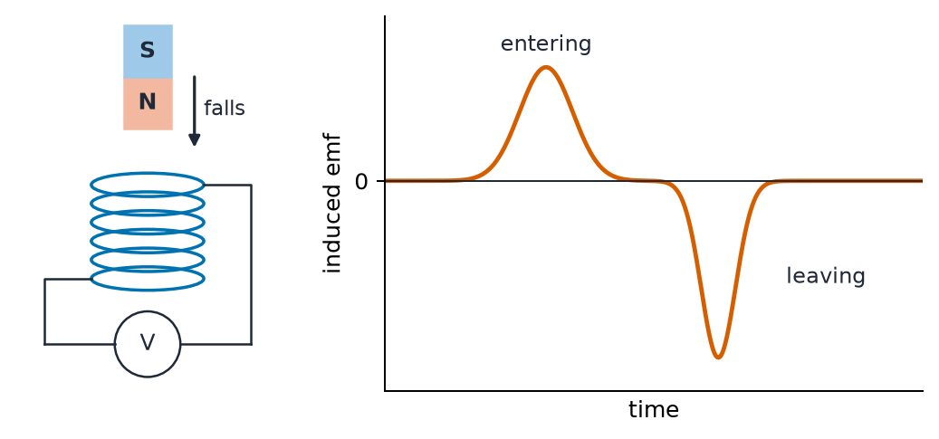
For two isolated emf pulses with equal initial and final flux linkage, what is necessarily equal in magnitude?
Difficulté 1/5 · 100 pièces + un petit bonus lors de la première réussite aujourd'hui
The integral of emf is minus total linkage change. Equal endpoints give zero total signed area, not equal peaks or widths.
AHL: apply Lenz direction to a specified change
- Lenz's law says the induced effect opposes the change that produces it. Push a north pole towards a passive closed coil: increasing linked field induces a current whose near face becomes north and repels the approach. Pull that same pole away: the near face becomes south and attracts it back. Use the right-hand grip rule to translate the required pole into a current direction, stating which end you are viewing.
- The induced field does not always oppose the original field. During withdrawal it supports the original field as that field decreases. Likewise, “opposes motion” is useful for the specified passive magnet-and-coil arrangement, not a universal replacement for Lenz's law. A changing field can induce current with no moving part. If the circuit is open, an emf still has the Lenz polarity even though an ordinary resistive current cannot circulate through the gap.
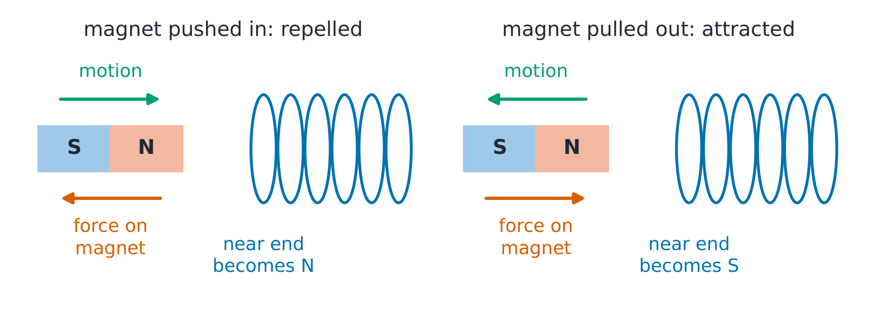
A north pole withdraws from a passive closed coil. What is the near coil face and current viewed from that pole?
Difficulté 1/5 · 100 pièces + un petit bonus lors de la première réussite aujourd'hui
Withdrawal decreases linked field. An attracting south face supports that decreasing field and resists withdrawal; a south face has clockwise conventional current seen from outside.
AHL: derive the sliding-rod emf with its geometry
- In this arrangement the rod, its velocity and the field are mutually perpendicular. Positive charges moving right with a field out of the page feel force downward along the rod; electrons redistribute oppositely. Charge separation establishes an electric field. In the open-circuit steady separation, electric and magnetic forces balance, giving end-to-end voltage magnitude $\varepsilon=BvL$. It is not valid merely because some angle in an apparatus happens to be 90°; the rod must span the force direction.
- Joining the rails through a resistor completes a growing loop. Its area increases by $Lv\,\Delta t$, giving the same emf from flux change. An invented .25 m rod at 6.0 m/s in .50 T gives .75 V. With total resistance 1.5 Ω and negligible inductive transient, current is .50 A, downward through the rod in this diagram. An isolated moving rod can still have separated end charges; “no complete circuit” means no sustained circuit current, not no emf.

An invented .25 m rod moves at 6.0 m/s in .50 T, with rod, velocity and field mutually perpendicular. With total circuit resistance 1.5 Ω and negligible transients, find current magnitude.
Difficulté 2/5 · 140 pièces + un petit bonus lors de la première réussite aujourd'hui
ε = BvL = 0.50 × 6.0 × 0.25 = 0.75 V. Then I = ε/R = 0.75/1.5 = 0.50 A. An open-circuit rod could retain an emf while having no sustained loop current.
AHL: account for the mechanical input
- The current-carrying rod feels an opposing force of magnitude $BIL=.0625$ N in the invented example. Keeping its speed constant requires an equal external push. Mechanical input power is $Fv=.375$ W; electrical power is $\varepsilon I=.375$ W, equal to $I^2R$. Keep unrounded .0625 N until the final power calculation, then round to .063 N and .38 W. Using rounded force too early produces a small avoidable discrepancy.
- These equalities assume a resistive circuit, negligible wire resistance beyond the stated total, negligible mechanical friction, and no changing stored energy. In a real start-up, some input may change kinetic or magnetic energy. If no external push maintains the rod, its kinetic energy decreases instead. A magnetic force on each free charge does zero work; moving boundaries, electric forces and the external mechanical input together account for energy delivered to the circuit. Do not describe a static magnetic field as a fuel supply.
For the same invented rod, maintaining force is .0625 N and speed 6.0 m/s. Find mechanical input power in the steady resistive model.
Difficulté 2/5 · 140 pièces + un petit bonus lors de la première réussite aujourd'hui
P = Fv = .375 W = εI = I²R. Use unrounded force until the final rounding; the external mechanical input supplies the heating.
AHL: link coil-entry geometry to both graphs
- A rigid rectangular coil moving at constant speed into a sharp-edged uniform field gains overlap area at rate $Lv$. While only the leading side is within the field, emf magnitude is $NBvL$. When the complete coil is inside the uniform region, linkage is constant and net loop emf is zero. On exit the overlap decreases, reversing the emf. This is an idealisation: real field boundaries give rounded transitions.
- For an invented 50-turn square coil of side .10 m moving at 2.0 m/s through a .30 m wide .40 T region, entry lasts .050 s and gives 4.0 V magnitude. Complete linkage is .20 Wb. The fully enclosed interval lasts $(.30-.10)/2.0=.10$ s; exit gives the opposite 4.0 V for .050 s. Distinguish flux per turn from total linkage and coil width from field-region width. In the figure, emf is the negative linkage gradient, not a copy of the flux curve.

An invented .10 m square coil moves at 2.0 m/s through a .30 m wide uniform field region. How long is the complete coil fully inside?
Difficulté 2/5 · 140 pièces + un petit bonus lors de la première réussite aujourd'hui
Complete enclosure lasts (field width − coil width)/speed = (.30 − .10)/2.0 = .10 s. Entry and exit each last .050 s, rather than .10 s.
AHL: explain braking without confusing its cause
- A moving magnet changes the flux through conducting paths in a copper pipe. Circulating eddy currents create an effect opposing the fall, and electrical resistance converts transferred energy into thermal energy. This does not require copper to be attracted like iron. An otherwise comparable insulating pipe cannot support these substantial conduction-current loops, so it lacks this strong eddy-current braking effect.
- For a conducting plate crossing a bounded field, closed current paths are possible within the metal even without an external wire. Slots that interrupt those paths can reduce braking. Do not infer that every metal translating anywhere in a uniform field is strongly braked: the field pattern, boundary motion and available current paths matter. In the passive case energy comes from mechanical work or lost kinetic/gravitational energy, with transient magnetic storage possible. A completely open pickup coil can show voltage without the same loaded braking force.
Which change tends to reduce eddy-current braking in a conducting plate for a stated changing-flux geometry?
Difficulté 1/5 · 100 pièces + un petit bonus lors de la première réussite aujourd'hui
Slots can interrupt closed conducting paths and reduce induced currents. Braking transfers mechanical energy; it is not evidence that the field provides fuel.
AHL: relate rotating-coil phase to peak emf
- Choose time zero with the coil's normal along a uniform field. Then linkage is $NBA\cos\omega t$ and emf is $NBA\omega\sin\omega t$. Emf is zero at both maximum positive and minimum negative linkage; its magnitude is greatest when linkage passes through zero. Stating only “maximum flux” can hide the negative extremum. The plane of the coil is perpendicular to the field at the extrema and parallel at the zero crossings.
- At fixed $N$, $B$ and $A$, doubling angular speed doubles peak emf and frequency, while linkage amplitude is unchanged. For an invented 100-turn .010 m² coil at 50 revolutions per second in .20 T, $\omega=2\pi f=314.16\ \dfrac{\mathrm{rad}}{\mathrm s}$ and peak emf is 62.83 V. A graph of twice the speed must have both twice as many cycles and twice the voltage amplitude. The sine sign depends on the initial orientation and chosen leads.
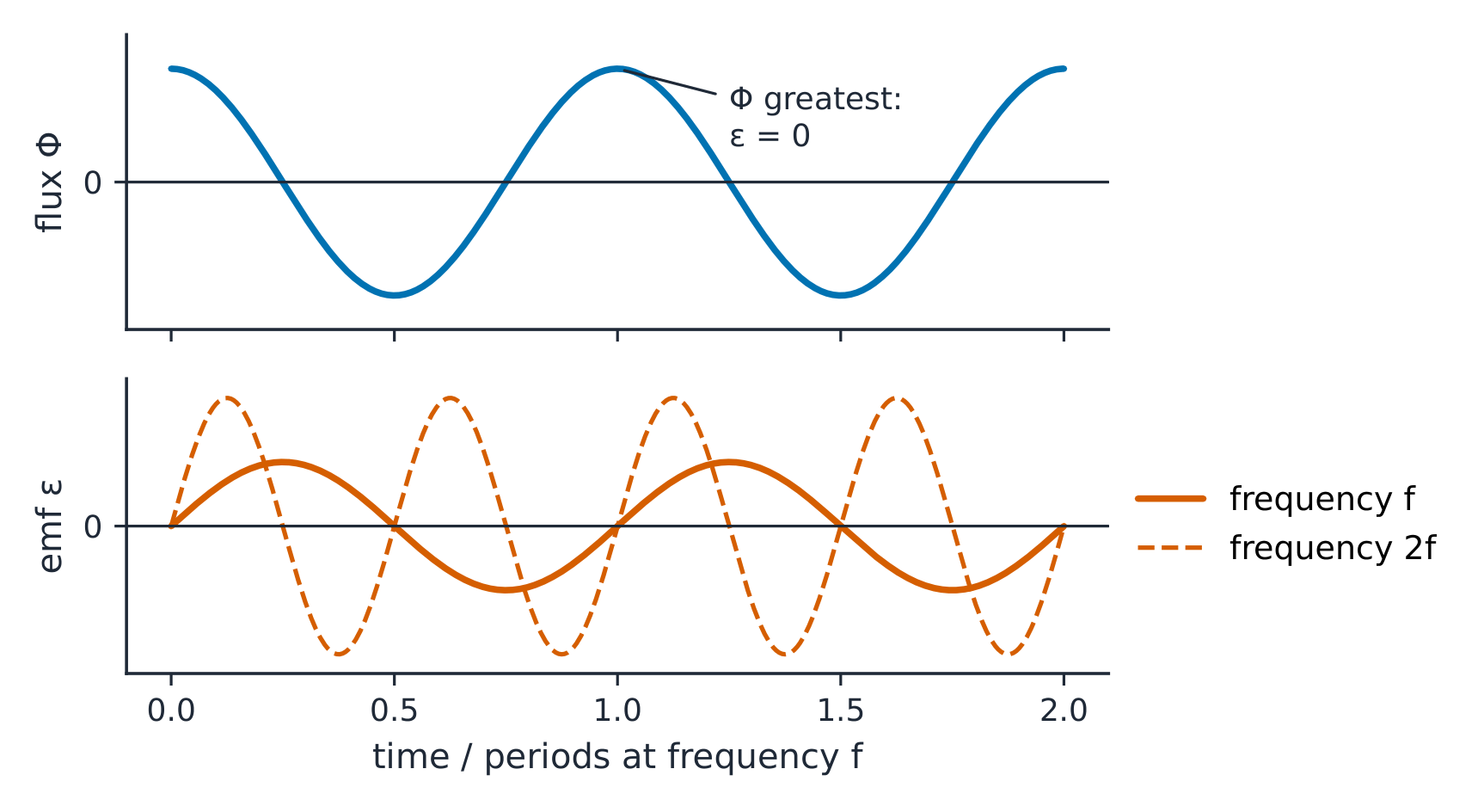
An invented coil has N = 80 turns, area .020 m² and B = .15 T, rotating at 20 revolutions per second. Find peak induced emf.
Difficulté 2/5 · 140 pièces + un petit bonus lors de la première réussite aujourd'hui
ω = 2πf = 2π × 20 = 125.664 rad/s. Peak emf ε₀ = NBAω = 80 × 0.15 × 0.020 × 125.664 = 30.1593 V ≈ 30 V. Doubling f would double peak and frequency, but not linkage amplitude.
AHL: use an ideal transformer ratio carefully
- The same changing core flux linking each turn gives the ideal voltage ratio $V_s/V_p=N_s/N_p$. Use matching quantities, such as both rms values for the same waveform; do not mix a peak voltage with an rms voltage. An invented 250-turn primary at 20 V with 100 secondary turns gives 8 V. This ratio describes induced emf; the ideal terminal-voltage approximation neglects winding resistance and leakage.
- A steady current makes a steady flux and gives no continuing secondary emf. Switching and pulses can create transient induction, so “DC never produces any emf” is too broad. A real transformer should not be connected to a steady DC voltage supply as though it were an AC transformer: transients, resistance and possible core saturation matter. An ideal zero-resistance primary with a maintained nonzero voltage would demand changing flux rather than an ordinary steady operating state. Distinguish fixed current from fixed voltage when explaining the limitation.
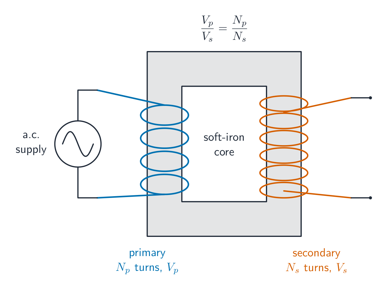
An invented ideal transformer has 250 primary turns, 100 secondary turns and 20 V rms primary voltage. Find secondary rms voltage.
Difficulté 2/5 · 140 pièces + un petit bonus lors de la première réussite aujourd'hui
Vs = Vp Ns/Np = 20 × 100/250 = 8 V rms. Compare matching voltage measures and state the ideal fully linked, negligible-resistance model.
AHL: follow self-induction through switching
- When a coil's own current changes, its linked flux changes and induces an emf in the coil itself. This self-induced emf opposes the change in current: it resists a rise at switch-on and supports the previous current direction at switch-off. In a simple circuit with resistance and inductance, current rises gradually towards its final value instead of jumping immediately. Opposing a change is different from always opposing the current.
- Opening a switch can demand a rapid current change, creating a large voltage that may drive a spark or current through a protective path. Energy previously stored in the magnetic field is then transferred elsewhere; the coil does not generate unlimited energy. The switching behaviour depends on resistance, winding/core properties and the available discharge path. Here qualitative reasoning is sufficient: identify the changing current, changing self-flux, induced polarity and destination of the stored energy.
When a coil current is being switched off, what does its self-induced emf tend to do?
Difficulté 1/5 · 100 pièces + un petit bonus lors de la première réussite aujourd'hui
Lenz polarity opposes the decrease in current, not the previous current itself. A large switch voltage may allow a spark or protective discharge path.
AHL: build a complete induction explanation
- Start with a surface normal, field direction and circuit orientation. State which of field, linked area, angle or turn linkage changes. Decide whether a finite difference gives an average or whether a local graph gradient is needed. Infer emf direction from the change, and only then infer current if a path exists. For a moving coil, check entry, complete enclosure and exit separately; for a rotating coil, distinguish the linkage extrema from its steepest slopes.
- Finish with energy and evidence. A pulse-area check tests total linkage change; repeated voltage-versus-rate readings test the proportional model. State which resistance, loading, motion or geometry assumptions justify an energy equality. Explain transformer induction through shared changing flux and self-induction through a coil's own changing current. Preserve the difference between steady current and steady voltage. Use invented numerical examples as model tests, rather than evidence about a particular real machine or exam paper.
Invented total linkage falls linearly from .12 Wb at .100 s to 0 Wb at .120 s. Find signed emf; the graph already includes all turns.
Difficulté 2/5 · 140 pièces + un petit bonus lors de la première réussite aujourd'hui
ε = −Δ(NΦ)/Δt = −(0 − .12)/.020 = +6 V. Do not multiply the stated total linkage by N again.
Explain induction through a moving magnet, a sliding rod, a rotating coil and a transformer. Include flux sign, average and instantaneous emf, current paths, energy, and self-induction.
Connect every equation to a changing linkage and a stated circuit. Correct numerical ratios alone do not explain induction direction, energy or operating limits.