Current, potential difference and resistance
Introducido| English | Significado |
|---|---|
| current/ˈkʌrənt/ | corriente eléctrica |
| potential difference/pəˈtenʃl ˈdɪfrəns/ | diferencia de potencial |
What would explain this observation?
- A lamp becomes dimmer when another is added in series. Current 电流 and energy transfer depend on the whole circuit, not only one lamp.
Build the model
- Current is charge passing per time.
- Potential difference 电势差 is energy transferred per charge.
- Resistance is potential difference divided by current for a stated operating point.
- current: Rate of flow of charge.
- potential difference: Energy transferred per unit charge.

How is a voltmeter connected to measure voltage across a resistor?
Dificultad 1/5 · 100 monedas + un pequeño bono en el primer intento de hoy
A voltmeter measures the potential difference between two points, so it connects in parallel across the component. In series it would add its very large resistance to the circuit and the current would collapse.
Match each technical term to its precise meaning.
Dificultad 2/5 · 140 monedas + un pequeño bono en el primer intento de hoy
Use the definitions to distinguish related quantities and processes.
Choose evidence that can test it
- Current is the same through components in series.
- Potential differences add around the series path.
- In parallel, branches share the same potential difference, while branch currents sum at a junction.
In the lab: Place an ammeter in series and a voltmeter in parallel. For an I-V investigation, change voltage in steps, reverse polarity when appropriate and limit current to reduce heating.
Which two habits make the investigation or model in this case more defensible?
Dificultad 2/5 · 140 monedas + un pequeño bono en el primer intento de hoy
Stating the conditions and assumptions lets others repeat the work exactly, and recording the supporting evidence lets them check the conclusion. Hiding disagreeing results removes the evidence that could challenge a wrong conclusion, and one measurement can never establish a wider claim.
Work from known quantities
- Known: a resistor has 6.0 V across it and carries 0.30 A.
- Use R = V/I.
- R = 6.0/0.30 = 20 ohms.
- Power = VI.
- Power = 6.0×0.30 = 1.8 W.
- These quantities describe the same operating point.
Your turn: A component has 12 V across it and carries 0.40 A. Find resistance.
One operating point: voltage, current and resistance
$I=\frac{V}{R};\quad P=VI$
At the worked operating point, 6 V across 20 ohms produces 0.30 A and 1.8 W.
A component has 12 V across it and carries 0.40 A. Find resistance.
Dificultad 2/5 · 140 monedas + un pequeño bono en el primer intento de hoy
The result is 30 Ω. Known: V = 12 V; I = 0.40 A. Use R = V/I. R = 12/0.40 = 30 ohms. This describes the component at that operating point; a filament lamp need not keep this resistance at other voltages.
Check the conclusion and its limits
- Current is not used up by a lamp.
- A filament heats up, so its resistance need not remain constant as voltage changes.
Not true: A lamp uses up electric current as charge passes through it. Current is a flow of charge, and charge is conserved: the same current enters and leaves a lamp. The lamp transfers energy from the charges to heat and light; it does not consume the charges.
- Current is charge passing per time.
- Current is the same through components in series.
- Watch for: current is not used up by a lamp.
A lamp uses up electric current as charge passes through it.
Dificultad 1/5 · 100 monedas + un pequeño bono en el primer intento de hoy
Current is a flow of charge, and charge is conserved: the same current enters and leaves a lamp. The lamp transfers energy from the charges to heat and light; it does not consume the charges.
Rate of flow of charge: write the technical term.
Dificultad 1/5 · 100 monedas + un pequeño bono en el primer intento de hoy
current means Rate of flow of charge.
Calculate resistance and power from voltage and current
- A component has 9 V across it and carries 0.25 A.
- Find the resistance and the power. A lamp does not use up current.
A component has 9 V across it and carries 0.25 A. What are the resistance and the power, and why does a lamp not use up current?
At this operating point, R = V/I = 9/0.25 = 36 ohms. Electrical power P = VI = 9 × 0.25 = 2.25 W. Check with I²R = 0.25² × 36 = 2.25 W. In steady operation charge does not build up in the lamp, so current entering equals current leaving; energy is transferred, not current consumed.
In the written case, the component has 9 V across it and current .25 A. What is its resistance?
Dificultad 1/5 · 100 monedas + un pequeño bono en el primer intento de hoy
9 divided by 0.25 is 36 ohms. Other options — 30 ohms (the lesson component at 12 V and 0.40 A); 2.25 W (the power).
Separate charge flow from energy transfer
- A battery transfers energy as charge circulates through a complete circuit. Components transfer that energy into light, heating, sound or other stores; they do not use up charge. In a steady series circuit, the charge passing each point per second is the same. If charge initially accumulates somewhere, its electric field changes; the steady-current rule describes the resulting settled circuit.
- All numerical cases below are invented teaching models. Wires and meters are ideal and sources have negligible internal resistance unless specified. Conventional current follows positive-charge motion. In a metal, negatively charged electrons drift in the opposite direction; in an electrolyte, positive and negative ions can both carry current. Do not infer carrier direction solely from the arrow for conventional current.
Convert time and count the charge carriers
- Average current is $I=\Delta q/\Delta t$, with amperes equal to coulombs per second. A model lamp passing 240 C in 2.0 minutes carries 240/120 = 2.0 A. If electron charge magnitude is $1.60\times10^{-19}$ C, the number of electrons passing per second is about $1.25\times10^{19}$. Use the charge magnitude when finding a positive count.
- Current describes a rate, not the total charge in a wire or the speed of each electron. A current of 0.30 A for 40 s transfers 12 C. The same charge through a component at 6.0 V transfers 72 J. Check the rate independently: power is 6.0 × .30 = 1.8 W, and 1.8 × 40 = 72 J. Convert minutes before applying an equation whose units are seconds.
An invented lamp passes 240 C in 2.0 minutes. Find the average current.
Dificultad 2/5 · 140 monedas + un pequeño bono en el primer intento de hoy
Convert 2.0 minutes to 120 s. I = Δq/Δt = 240/120 = 2.0 A. Charge per minute is not the numerical current in amperes.
Distinguish emf from a component's potential difference
- Emf is energy supplied by a source per unit charge; potential difference across a passive component describes energy transferred per unit charge. Both have units J/C, called volts. The term electromotive force does not mean a force measured in newtons. An ideal 9.0 V battery supplying 54 J has transferred 6.0 C through the source.
- A chemical cell converts chemical energy; a solar cell converts light energy. Rechargeable cells can restore chemical energy using an external supply, while primary cells are not designed for routine recharging. A solar cell requires illumination, including suitable artificial light; it has no fuel consumption during operation but has manufacture, ageing and replacement costs. Output voltage and current depend on the device, illumination and load, rather than every cell having one universal voltage.
An ideal 9.0 V source supplies 54 J of energy. Find the charge passing through the source.
Dificultad 2/5 · 140 monedas + un pequeño bono en el primer intento de hoy
Emf is energy supplied per charge, so q = W/ε = 54/9 = 6.0 C. Emf is measured in volts, not newtons.
Connect meters to measure the intended quantity
- An ammeter measures current through its branch, so connect it in series. An ideal ammeter has zero resistance; connecting it across a source would approximate a short circuit rather than measure a component's current. A voltmeter measures the potential difference between two nodes, so connect it in parallel. An ideal voltmeter has infinite resistance and draws no current.
- Real meters alter the circuit: ammeter resistance can reduce current, and finite voltmeter resistance provides an extra parallel path. For a low-voltage current–voltage investigation, use approved current limits, open the switch between readings when heating must be controlled, and reverse polarity only when the component and apparatus permit it. Record voltage across the component, not an assumed unchanged supply setting.
Which connection measures a resistor’s current and potential difference with ideal meters?
Dificultad 1/5 · 100 monedas + un pequeño bono en el primer intento de hoy
An ammeter carries the branch current and ideally has zero resistance. A voltmeter compares the component’s two endpoint potentials and ideally draws no current. A parallel ideal ammeter would short-circuit the component.
Use resistance at an operating point
- Resistance at a stated operating point is R = V/I. A component with 6.0 V across it carrying 0.30 A has R = 20 Ω and power 1.8 W. At 3.0 V and .25 A a different operating point has R = 12 Ω. The definition does not itself prove that resistance remains constant when voltage or temperature changes.
- Ohm's law describes proportional current and potential difference with physical conditions, including temperature, fixed. On a graph of I vertically against V horizontally, an ohmic line through the origin has gradient 1/R. For a curved graph, V/I uses the coordinates of the point, not the local tangent gradient. A graph with V vertically and I horizontally instead has an ohmic gradient R; read the axes first.
Explain a filament's changing current–voltage curve
- The model ohmic resistor shown has constant R = 12 Ω, giving 0.50 A at 6.0 V. The filament's curve becomes less steep as the magnitude of voltage rises because its higher temperature increases resistance. In the illustrative curve, 1.0 V gives about .185 A and resistance about 5.4 Ω, whereas 6.0 V gives .50 A and 12 Ω. These are invented model points, not measurements from a named lamp.
- In a metal, electron scattering transfers energy to the lattice; stronger thermal vibrations generally increase resistivity over the relevant range. The filament is not consuming current or creating extra charge. With reversed voltage, current reverses too for this symmetric model. A nonlinear relationship must be used at the actual operating point rather than extrapolating a constant low-voltage resistance.

On a curved I-versus-V graph for a warming filament, how do you obtain its resistance at a point?
Dificultad 1/5 · 100 monedas + un pequeño bono en el primer intento de hoy
Operating-point resistance is V/I. A local tangent describes a small-change ratio and differs from the origin-to-point ratio for a nonlinear curve. Heating changes the filament’s resistance.
Include wire geometry and physical conditions
- For a uniform wire, $R=\rho L/A$, with resistivity ρ in Ω m. Resistivity depends on material and physical conditions such as temperature; it is not a measure of wire length. For a circular wire of diameter .50 mm, radius is .25 mm and area is about $1.963\times10^{-7}$ m². A 2.0 m wire with specified resistivity $1.7\times10^{-8}$ Ω m has resistance about .173 Ω.
- At unchanged resistivity, doubling length doubles resistance, while doubling diameter quadruples area and reduces resistance by a factor of four. Doubling both length and diameter therefore halves resistance. A wire with R = .13 Ω, area $2.0\times10^{-7}$ m² and length 1.5 m has resistivity about $1.73\times10^{-8}$ Ω m. That is consistent with the model copper value; resistance alone does not uniquely identify a material without geometry and temperature information.
A uniform wire is replaced by the same material at unchanged temperature, twice as long and twice the diameter. Find new resistance divided by old resistance.
Dificultad 2/5 · 140 monedas + un pequeño bono en el primer intento de hoy
R = ρL/A. Length doubles and circular area quadruples, so Rnew/Rold = 2/4 = .50. Doubling diameter does not merely double area.
Check power and transferred energy independently
- For a passive resistive component, power P = IV, with equivalent forms I²R and V²/R using its actual R at that operating point. Energy over a constant-power interval is Pt. An invented 2.3 kW resistive kettle on 230 V draws 10 A and has operating resistance 23 Ω. Over 3.0 minutes, its electrical energy input is 414,000 J, about 410 kJ to two significant figures.
- Electrical input need not equal useful energy gained by the water: some heats the kettle and surroundings. In a cable with unchanged resistance, halving current quarters I²R heating power. At fixed delivered power, higher transmission voltage allows lower current; simply halving the current through a fixed-voltage load would also change its delivered power. State which quantities stay fixed when comparing losses.
An invented resistive kettle has constant electrical input power 2.3 kW for 3.0 minutes. Find input energy in joules.
Dificultad 2/5 · 140 monedas + un pequeño bono en el primer intento de hoy
Convert to 2300 W and 180 s. E = Pt = 2300 × 180 = 414000 J, about 4.1 × 10⁵ J. Useful energy gained by water may be smaller than electrical input.
Use nodes and conservation in series and parallel
- Components are in series when there is one unbranched path, so their current is the same. Their voltage drops add and resistances sum. Parallel branches connect the same pair of nodes, so share the same potential difference, while branch currents add. Physical placement on the page is not the definition: trace which wires connect the endpoints.
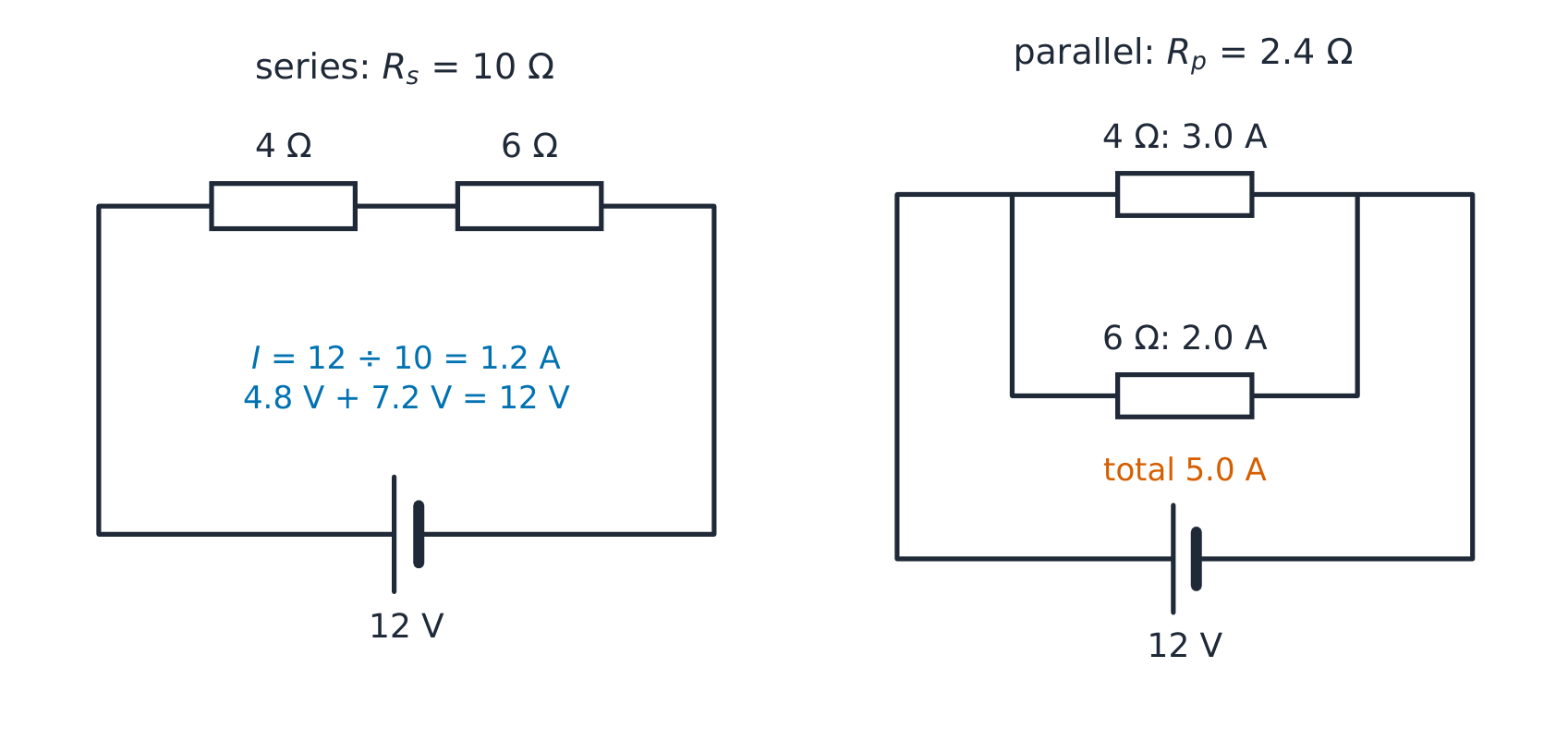
- With an ideal 12 V source, series 4 Ω and 6 Ω resistors have total 10 Ω, current 1.2 A and voltage drops 4.8 and 7.2 V. In parallel, total resistance is 2.4 Ω and branch currents 3.0 and 2.0 A, totalling 5.0 A. Charge conservation checks the current sums; energy per coulomb checks the voltage sums. A parallel total is below the smallest positive branch resistance.
Reduce a combined network and work back through it
- Put a 2.0 Ω resistor in series with a parallel pair of 6.0 Ω and 3.0 Ω across an ideal 12 V source. The pair has equivalent resistance 2.0 Ω, so total resistance is 4.0 Ω and supply current 3.0 A. The first resistor drops 6.0 V, leaving 6.0 V across each parallel branch. Their currents are 1.0 and 2.0 A.
- Check power as well as current: the series resistor dissipates 18 W, the 6 Ω branch 6 W and the 3 Ω branch 12 W. Their 36 W total equals source power 12 × 3 = 36 W. Adding a parallel resistor reduces equivalent external resistance, but with a non-ideal source it can also reduce terminal voltage; do not assume an unchanged supply voltage unless the source model permits it.
An ideal 12 V source supplies a 2 Ω resistor in series with a parallel pair of 6 Ω and 3 Ω. Find current from the source.
Dificultad 2/5 · 140 monedas + un pequeño bono en el primer intento de hoy
The parallel pair gives 1/Rp = 1/6 + 1/3 = 1/2, so Rp = 2 Ω. Total resistance = 2 + 2 = 4 Ω and source current I = 12/4 = 3 A. The series resistor drops IR = 3 × 2 = 6 V, leaving 12 − 6 = 6 V across the parallel pair. Branch currents are 6/6 = 1 A and 6/3 = 2 A; 1 + 2 = 3 A checks charge conservation.
Include a source's internal resistance
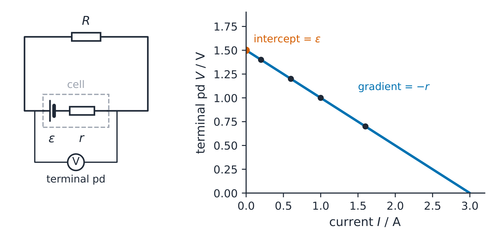
- For a discharging cell model with emf ε and internal resistance r feeding load R, current is ε/(R + r). Terminal voltage is V = ε − Ir = IR. For ε = 6.0 V, r = .50 Ω and R = 2.5 Ω, current is 2.0 A and terminal voltage 5.0 V. The internal voltage drop is 1.0 V, not one joule of total energy: it means one joule per coulomb.
- Source power is εI = 12 W, load power IV = 10 W and internal heating I²r = 2 W. When no current flows, this model gives terminal voltage equal to emf. The equation with the minus sign describes discharge; it is not a universal rule that terminal voltage must be below emf during externally driven charging. Real sources can also depart from a constant-r model as temperature and state of charge change.
A discharging model cell has emf 6.0 V and internal resistance .50 Ω, connected to external resistance 2.5 Ω. Find internal heating power.
Dificultad 2/5 · 140 monedas + un pequeño bono en el primer intento de hoy
Current I = 6/(2.5 + .5) = 2 A. Internal power = I²r = 4 × .5 = 2 W. The source supplies 12 W while the external resistor receives 10 W.
Extract emf and internal resistance from the graph
- In the illustrative constant-parameter cell model, terminal voltage against current is a straight line, V = ε − rI. The voltage-axis intercept is ε and the gradient is −r. Points such as (.20 A, 1.40 V) and (1.0 A, 1.0 V) give slope −.50 V/A, so r = .50 Ω and the intercept is 1.50 V. Use two well-separated points on a fitted line rather than noisy neighbouring readings.
- A separate student-model graph with intercept 4.5 V and gradient −1.5 V/A indicates ε = 4.5 V and r = 1.5 Ω. Control temperature and allow readings to settle; changing the load can change cell heating. The idealised graph's zero-voltage intercept must not be tested by deliberately short-circuiting a real source. The constant-r extrapolation does not justify exceeding equipment current limits.
A model terminal-voltage V against current I graph has voltage intercept 4.5 V and gradient −1.5 V/A. Find internal resistance.
Dificultad 2/5 · 140 monedas + un pequeño bono en el primer intento de hoy
V = ε − rI, so gradient is −r. Internal resistance is +1.5 Ω, while the intercept gives emf 4.5 V. The negative slope does not mean negative resistance.
Calculate unloaded potential-divider output
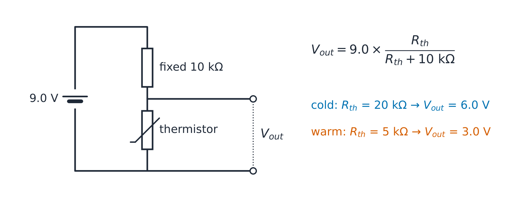
- For two series resistors across Vin, output across the lower R₂ is $V_{\rm out}=V_{\rm in}\dfrac{R_2}{R_1+R_2}$ when the output draws negligible current. In the illustrative 9.0 V circuit with fixed upper 10 kΩ, a lower thermistor at 20 kΩ takes 6.0 V; at 5 kΩ it takes 3.0 V. The supply current is the same through the two resistors before an extra output load is connected.
- A negative-temperature-coefficient thermistor decreases resistance as it warms. In this lower position, output therefore falls when warmed and rises when cooled. If the thermistor and fixed resistor exchange positions while output stays across the lower component, the response reverses. An LDR similarly decreases resistance with greater illumination; always identify the resistor across which output is measured.
A 9 V unloaded divider has a fixed upper resistor and an NTC thermistor below it. Output is across the thermistor. What happens when it warms?
Dificultad 1/5 · 100 monedas + un pequeño bono en el primer intento de hoy
Vout = Vin Rthermistor/(Rfixed + Rthermistor). Warming reduces the NTC resistance and therefore the output share. Reversing the components while keeping the lower output reverses the response.
Account for a load before reusing the divider formula
- An output load is in parallel with the lower divider resistor. For an ideal 12 V supply and two 10 kΩ divider resistors, unloaded output is 6.0 V. Connect a 10 kΩ load across the lower resistor: their parallel equivalent becomes 5 kΩ, so loaded output is 12 × 5/(10 + 5) = 4.0 V. The original 6.0 V cannot be used to calculate load current as if nothing changed.
- In that loaded case, upper current is .80 mA and each lower path carries .40 mA. The currents sum correctly, with 8.0 V across the upper resistor and 4.0 V across the lower paths. A high-input-resistance measuring device gives a smaller loading effect. A potentiometer's slider changes the resistance of each track segment; its full end-to-end resistance can remain unchanged while its output ratio varies.
An ideal 12 V source has two 10 kΩ series divider resistors. A 10 kΩ load is connected across the lower resistor. Find loaded output voltage.
Dificultad 2/5 · 140 monedas + un pequeño bono en el primer intento de hoy
Lower resistor and load are in parallel, giving 5 kΩ. Vout = 12 × 5/(10 + 5) = 4 V. The original unloaded 6 V no longer applies; upper .8 mA splits into two .4 mA paths.
Choose a device model and evaluate evidence
- A fixed resistor, warming filament, negative-temperature-coefficient thermistor and LDR have different responses; the algebra R = V/I does not make them all ohmic. Specify material and temperature for resistivity, output terminals for a divider, and discharge conditions for V = ε − Ir. Identify meter loading or self-heating before interpreting a departure as failure of charge conservation.
- For any numerical circuit, redraw connected nodes, simplify genuine series/parallel sections, then find source current, branch voltages and branch currents in that order. Finally check charge flow at junctions, voltage sums round complete loops and total power. Report units and sensible precision; original experimental data, if collected, should retain uncertainty and any justified correction rather than being replaced by an ideal curve.
Explain how to analyse and check a dc circuit with a non-ideal source and a sensor divider. Include graph interpretation and model conditions.
A reliable circuit solution uses the whole connected system, the correct device model and independent conservation checks.