Potential dividers
| English | Chinese | Pinyin |
|---|---|---|
| potential divider | 分压器 | fēn yā qì |
| load | 负载 | fù zài |
| thermistor | 热敏电阻 | rè mǐn diàn zǔ |
| threshold | 阈值 | yù zhí |
| potentiometer | 电位差计 | diàn wèi chà jì |
| null method | 零点法 | líng diǎn fǎ |
| galvanometer | 检流计 | jiǎn liú jì |
| balance length | 平衡长度 | píng héng cháng dù |
The volume knob
- A volume or dimmer knob can set the output anywhere from off to full.
- Inside is a potential divider 分压器 — resistors sharing out the voltage.
- It turns a fixed supply into any voltage you want.
Splitting the voltage
- Two resistors in series share the supply in proportion to their resistance.
- Tapped across $R_2$: $V_{\text{out}} = V_{\text{in}}\dfrac{R_2}{R_1 + R_2}$.
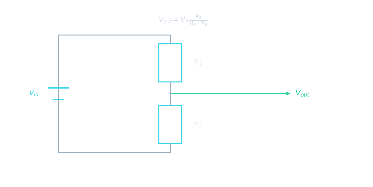
Sharing voltage in series
In a series loop the same current flows everywhere and the cell's voltage splits across the components — that split is how a potential divider works.
A $12\ \text{V}$ supply is across $R_1 = 2.0\ \text{k}\Omega$ and $R_2 = 4.0\ \text{k}\Omega$ in series. What is the output across $R_2$?
$V_{\text{out}} = V_{\text{in}}\dfrac{R_2}{R_1+R_2} = 12 \times \dfrac{4.0}{2.0+4.0} = 8.0\ \text{V}$.
In a potential divider, the p.d. across each resistor is proportional to its resistance.
The same current flows through both, so $V = IR$ means the bigger resistor takes the bigger share.
Worked example: a divider, then a load
A $12\ \text{V}$ supply is connected across $R_1 = 3.0\ \text{k}\Omega$ and $R_2 = 1.0\ \text{k}\Omega$ in series. Find the output across $R_2$. A $1.0\ \text{k}\Omega$ load 负载 is then connected across the output.
- Unloaded: $V_{\text{out}} = 12 \times \dfrac{1.0}{3.0 + 1.0} = 3.0\ \text{V}$.
- With the load: it sits in parallel with $R_2$, giving $\dfrac{1.0 \times 1.0}{1.0 + 1.0} = 0.50\ \text{k}\Omega$ in that position.
- Loaded output: $V_{\text{out}} = 12 \times \dfrac{0.50}{3.0 + 0.50} = 1.7\ \text{V}$.
- Check: connecting the load lowered the output — the divider only delivers its design voltage to a load whose resistance is much larger than $R_2$.
A $9.0\ \text{V}$ supply is across $R_1 = 6.0\ \text{k}\Omega$ and $R_2 = 3.0\ \text{k}\Omega$ in series, output across $R_2$. A $3.0\ \text{k}\Omega$ load is connected across the output. What is the output voltage now, in V?
The load in parallel with $R_2$ gives $1.5\ \text{k}\Omega$, so $V_{\text{out}} = 9.0 \times \dfrac{1.5}{6.0 + 1.5} = 1.8\ \text{V}$ — down from $3.0\ \text{V}$ unloaded.
Sensor circuits
- Swap a resistor for a thermistor 热敏电阻 → the output changes with temperature.
- Swap it for an LDR → the output changes with light.

A thermistor in a divider turns a temperature change into a changing output voltage
Replacing one resistor in a divider with an LDR makes the output voltage depend on:
An LDR's resistance changes with light, so its share of the voltage — the output — tracks the brightness.
Which way does the output go?
- The output across a resistor is that resistor's share of the supply, and the share grows when its resistance grows relative to the other.
- Thermistor as $R_1$, output across fixed $R_2$: temperature ↑ → thermistor resistance ↓ → $R_2$'s share ↑ → $V_{\text{out}}$ rises.
- LDR as $R_1$, light decreases: LDR resistance ↑ → $R_2$'s share ↓ → $V_{\text{out}}$ falls. Swap the two components to reverse the behaviour.
In each divider the output is taken across the fixed resistor. Match the change to what the output does.
When the sensor's resistance falls (hotter thermistor, brighter LDR), the fixed resistor takes a larger share of the supply and the output across it rises.
Switching at a threshold 阈值
- Feed the changing output to a transistor or comparator.
- It can switch a load on or off when the temperature or light passes a set threshold (e.g. a street lamp at dusk).
A sensor divider can switch a load on when the measured quantity crosses a set ____.
Feed the output to a comparator/transistor; it flips the load when the voltage passes the threshold (e.g. a lamp at dusk).
The potentiometer 电位差计 (null method 零点法)
- A uniform wire taps off $V_x = V_{\text{full}}\dfrac{x}{L_0}$ along its length — because for a uniform wire $R \propto L$, and with the same current everywhere $V = IR \propto L$.
- To compare e.m.f.s, slide until the galvanometer 检流计 reads zero — at balance no current flows through the test cell, so its internal resistance does not matter: $\dfrac{\varepsilon_1}{\varepsilon_2} = \dfrac{l_1}{l_2}$.

Slide the contact until the galvanometer reads zero — at balance the tapped length is proportional to the e.m.f.
At the balance point of a potentiometer, the current through the cell being measured is:
At balance the wire's p.d. exactly opposes the cell's e.m.f., so no current flows through it (a null).
At balance, the measured cell's internal resistance does not affect the result.
With zero current through the cell, there is no $Ir$ drop — so internal resistance has no effect. That is the strength of a null method.
Worked example: a balance length
A driver cell puts $2.0\ \text{V}$ across a uniform wire of length $100\ \text{cm}$. A test cell balances at a balance length 平衡长度 of $64\ \text{cm}$.
- e.m.f. of the test cell: $\varepsilon = 2.0 \times \dfrac{64}{100} = 1.28\ \text{V}$.
- If the test cell has internal resistance: no change — at balance no current flows through it, so there are no lost volts.
- If the driver cell has internal resistance: the p.d. across the wire is less than $2.0\ \text{V}$, so a longer length is needed for the same $1.28\ \text{V}$: the balance point moves further along the wire.
- Check: the balance length can never exceed the wire, so a test cell with an e.m.f. above the p.d. across the wire cannot be balanced at all.
A driver cell puts $1.5\ \text{V}$ across a $100\ \text{cm}$ uniform potentiometer wire. A test cell balances at $80\ \text{cm}$. What is its e.m.f., in V?
The p.d. along the wire is proportional to length: $\varepsilon = 1.5 \times \dfrac{80}{100} = 1.2\ \text{V}$.
A divider's output is only $V_{\text{in}}\dfrac{R_2}{R_1 + R_2}$ with nothing connected — a load in parallel with $R_2$ lowers it. In the potentiometer, "no current at balance" is what makes it a null method: the test cell's internal resistance drops out, but the driver cell's does not. And "the balance length is proportional to the e.m.f." holds only because the wire is uniform.
You've got it
- a divider shares voltage by resistance: $V_{\text{out}} = V_{\text{in}}\dfrac{R_2}{R_1 + R_2}$; a load across the output lowers it
- a thermistor or LDR makes the output respond to heat or light — the output across the fixed resistor rises when the sensor's resistance falls
- the null method: balance for zero current, so the test cell's internal resistance has no effect; $\dfrac{\varepsilon_1}{\varepsilon_2} = \dfrac{l_1}{l_2}$