| Learning Objective | Essential Knowledge |
|---|---|
5.1.A |
Boundary statement: AP Physics C: Mechanics expects students to be able to mathematically manipulate the magnitudes of angular displacement, angular velocity, and angular acceleration using vector conventions. However, the directions of said vectors will not be assessed on the exam. Descriptions of the directions of rotational kinematics quantities for a point or rigid body are limited to clockwise and counterclockwise with respect to a given axis of rotation. |
Torque and Rotational Dynamics
AP Physics C: Mechanics · Topic 5
 7:22
7:22
Torque and Rotational Dynamics
Push a door at the handle and it swings open easily. Now push just as hard, right next to the hinge. Almost nothing happens. The force was the same both times.…
English narration · English + 中文 subtitles burned in
5.1
Rotational Kinematics
Syllabus
Source: College Board AP Course and Exam Description
A fan can keep turning while it slows down. Its velocity and acceleration then have opposite signs. Choose one fixed axis and a positive sense, such as counterclockwise. A rigid body 刚体 holds its shape; its points share the same angular motion about that axis.
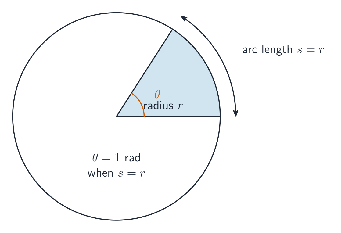
Angular displacement 角位移 is $\Delta\theta=\theta-\theta_0$, measured in radians 弧度. One revolution is $2\pi$ radians. Angular velocity 角速度 and angular acceleration 角加速度 are rates:
$$\omega=\frac{d\theta}{dt},\qquad\alpha=\frac{d\omega}{dt}.$$
The AP rotational-kinematics descriptions use clockwise/counterclockwise signs; three-dimensional directions of these kinematic vectors are outside this unit's assessment boundary. Torque directions are considered separately below.
For constant $\alpha$ only,
$$\omega=\omega_0+\alpha t,\qquad\Delta\theta=\omega_0t+\frac12\alpha t^2,\qquad\omega^2=\omega_0^2+2\alpha\Delta\theta.$$
For varying acceleration, retain the initial conditions:
$$\omega(t)=\omega_0+\int_0^t\alpha(t')\,dt',\qquad\theta(t)=\theta_0+\int_0^t\omega(t')\,dt'.$$
Slope of a $\theta$–$t$ graph gives $\omega$; slope of an $\omega$–$t$ graph gives $\alpha$. Signed area under $\omega(t)$ gives angular displacement; it need not equal total angle travelled after reversal.
Original constant-acceleration task. A fan slows from $30$ rad/s to rest at constant $\alpha=-6.0$ rad/s². From $\omega=\omega_0+\alpha t$, $t=(0-30)/(-6.0)=5.0$ s. Then $\Delta\theta=\omega_0t+\frac12\alpha t^2=75$ rad, or $75/(2\pi)\approx12$ revolutions. Stop the model at rest unless the driving torque is specified to continue.
Original variable-acceleration task. Let $\alpha=ct$, with $c=4.0$ rad/s³, $\omega_0=3.0$ rad/s and $\theta_0=1.0$ rad. Integration gives $\omega=\omega_0+\frac12ct^2$ and $\theta=\theta_0+\omega_0t+ct^3/6$. At $t=2.0$ s, these are $11$ rad/s and $12.3$ rad. Omitting the integration constants changes the physical initial state.
Vocabulary
Train
| English |
|---|
| angular displacement/ˈæŋɡjʊlə dɪˈspleɪsmənt/ |
| radians/ˈreɪdɪənz/ |
| angular velocity/ˈæŋɡjʊlə vəˈlɒsɪti/ |
| angular acceleration/ˈæŋɡjʊlə əkˌseləˈreɪʃn/ |
| rigid body/ˈrɪdʒɪd ˈbɒdi/ |
5.2
Connecting Linear and Rotational Motion
Syllabus
| Learning Objective | Essential Knowledge |
|---|---|
5.2.A |
Boundary statement: AP Physics C: Mechanics expects students to be able to mathematically manipulate the magnitudes of angular displacement, angular velocity, and angular acceleration using vector conventions. However, the directions of the vectors will not be assessed on the exam. Descriptions of the directions of rotational kinematics quantities for a point or rigid body are limited to clockwise and counterclockwise with respect to a given axis of rotation. |
Source: College Board AP Course and Exam Description
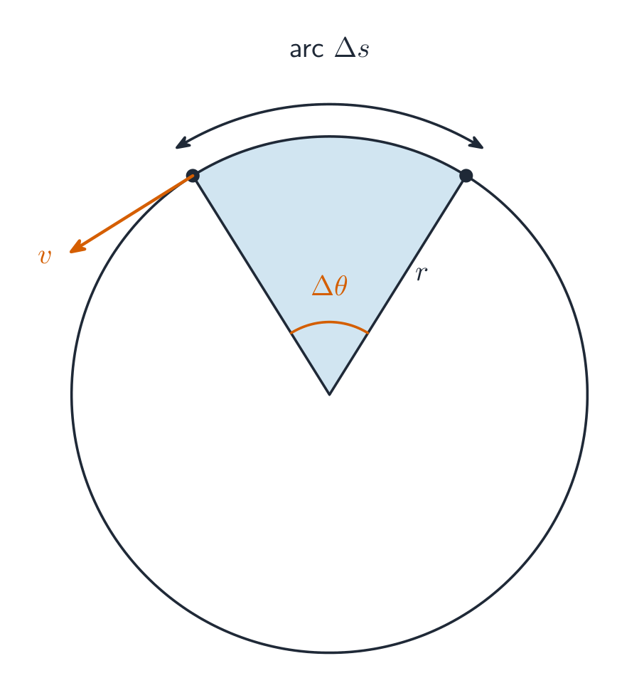
For a point at perpendicular distance $r$ from a fixed axis,
$$\Delta s=r\Delta\theta,\qquad v=r|\omega|,\qquad a_t=r\alpha,\qquad a_c=r\omega^2.$$
Here $v$ is speed; $a_t$ is signed relative to the chosen tangential direction. The tangential acceleration 切向加速度 changes speed and may oppose motion. The centripetal acceleration 向心加速度 points toward the axis and changes direction. Their perpendicular magnitudes give $a=\sqrt{a_t^2+a_c^2}$. Constant nonzero angular speed still gives centripetal acceleration.
Original wheel task. At one instant $\omega=4.0$ rad/s and $\alpha=-2.0$ rad/s². At $r=0.50$ m, $v=r|\omega|=2.0$ m/s, $a_t=r\alpha=-1.0$ m/s² and $a_c=r\omega^2=8.0$ m/s². Thus $a=\sqrt{(-1.0)^2+8.0^2}=8.1$ m/s². At twice the radius all three component magnitudes double, although $\omega$ and $\alpha$ are unchanged.
Vocabulary
Train
| English |
|---|
| tangential acceleration/tænˈdʒenʃl əkˌseləˈreɪʃn/ |
| centripetal acceleration/senˈtrɪpɪtl əkˌseləˈreɪʃn/ |
5.3
Torque
Syllabus
| Learning Objective | Essential Knowledge |
|---|---|
5.3.A |
|
5.3.B |
|
Source: College Board AP Course and Exam Description
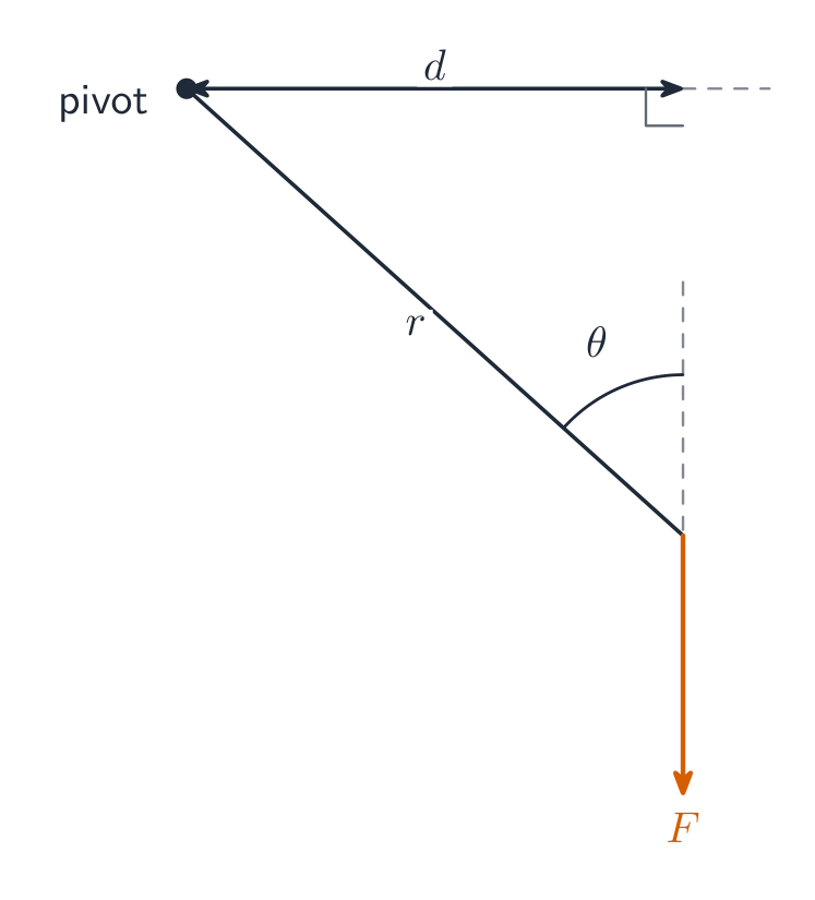
Torque 力矩 describes a force's turning effect about a chosen axis. It is a vector product 矢量积:
$$\vec\tau=\vec r\times\vec F,\qquad |\tau|=rF\sin\phi=F r_\perp.$$
The moment arm 力臂 $r_\perp$ is the perpendicular distance from the axis to the force's line of action, not necessarily the distance to its application point. A force whose line of action passes through the axis has zero torque about that axis; it can still exert a force and cause translation.
The right-hand rule 右手定则 gives the torque direction perpendicular to the plane of $\vec r$ and $\vec F$: curl from $\vec r$ toward $\vec F$. Counterclockwise torque is out of the page; clockwise is into it. For planar calculations choose signs consistently. Torque has unit N m, but it is not the scalar work measured in joules.
Original lever task. A $20$ N force acts at $r=0.30$ m and angle $30^\circ$ to the radius, tending counterclockwise. Its torque is $\tau=rF\sin\phi=(0.30)(20)\sin30^\circ=+3.0$ N m. Equivalently, $r_\perp=r\sin\phi=0.15$ m. A perpendicular $10$ N force at the same radius gives the same torque. More force alone does not determine more torque.
Explore
Balance torques on a beam
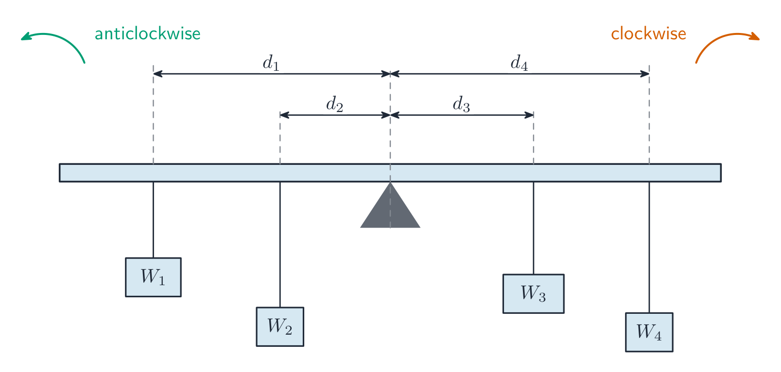
Torque is force times perpendicular distance, $\tau=Fd$. The beam is in rotational equilibrium when the torques on each side are equal.
Vocabulary
Train
| English |
|---|
| Torque/tɔːk/ |
| vector product/ˈvektə ˈprɒdʌkt/ |
| moment arm/ˈməʊmənt ɑːm/ |
| right-hand rule/raɪt hænd ruːl/ |
5.4
Rotational Inertia
Syllabus
| Learning Objective | Essential Knowledge |
|---|---|
5.4.A |
|
5.4.B |
Boundary statement: AP Physics C: Mechanics only expects students to use calculus in the derivations of the rotational inertia of thin rods of uniform or nonuniform density about an arbitrary axis perpendicular to the rod, as well as derivations of the rotational inertia of a thin cylindrical shell, disk, or rigid bodies that can be considered to be made up of coaxial rings or shells about an axis that passes through their centers (e.g., annular rings). Students should have a qualitative understanding of the factors that affect rotational inertia; for example, how rotational inertia is greater when mass is farther from the axis of rotation, which is why a hoop has more rotational inertia than a solid puck of the same mass and radius. |
Source: College Board AP Course and Exam Description
Rotational inertia 转动惯量 depends on the mass distribution relative to a specified axis:
$$I=\sum_i m_i r_i^2,\qquad I=\int r^2\,dm.$$
Use perpendicular distance from each mass element to that axis. The unit is kg m². For a point-mass model, moving the same mass from $r$ to $2r$ multiplies its contribution by four. Inertias add only when defined about the same axis.
Uniform rod about its centre. For mass $M$, length $L$ and linear density 线密度 $\lambda=M/L$, take $x=0$ at the centre. Then $dm=(M/L)dx$ and
$$I_{\rm cm}=\int_{-L/2}^{L/2}x^2\frac{M}{L}\,dx=\frac{ML^2}{12}.$$
Nonuniform rod about its light end. If $\lambda(x)=cx$ on $0\le x\le L$, $c$ has unit kg/m². First normalise the density:
$$M=\int_0^L cx\,dx=\frac12cL^2,\qquad c=\frac{2M}{L^2}.$$
Then $I=\int_0^L x^2(cx)dx=cL^4/4=ML^2/2$. This is not the uniform-rod result; the mass is concentrated farther from the axis.
Disk from coaxial rings. For a uniform thin disk, surface density is $\sigma=M/(\pi R^2)$. A thin ring has $dm=\sigma 2\pi r\,dr$, so
$$I=\int_0^R r^2\sigma2\pi r\,dr=\frac12MR^2.$$
A thin hoop of the same mass and radius has $I=MR^2$. For a uniform annular disk with inner radius $a$ and outer radius $b$, use $\sigma=M/[\pi(b^2-a^2)]$ and limits $a$ to $b$: $I=M(a^2+b^2)/2$. AP's calculus scope includes rods and bodies built from coaxial rings/shells; arbitrary three-dimensional shapes are not required here.
The parallel-axis theorem 平行轴定理 relates an axis through the centre of mass to a parallel axis a distance $d$ away:
$$I'=I_{\rm cm}+Md^2.$$
For the uniform rod about one end, $I=ML^2/12+M(L/2)^2=ML^2/3$. The starting axis must pass through the centre of mass. For $M=3.0$ kg and $L=2.0$ m, $I_{\rm cm}=1.0$ kg m² and $I_{\rm end}=4.0$ kg m².
Verified exam connection — 2023 Set 1 Q2(a). The question gives $T=2\pi\sqrt{I/\kappa}$ for a torsional pendulum and $I_{\rm disk}=MR^2/2$. For $N$ identical coaxial disks moving together, $I_{\rm total}=NMR^2/2$, so $T=2\pi\sqrt{NMR^2/(2\kappa)}$. Four times as many disks doubles the period, not quadruples it. The official scheme checks the summed inertia and consistent substitution. The period relation is supplied here; its oscillation derivation belongs to the oscillations unit.
Vocabulary
Train
| English |
|---|
| Rotational inertia/rəʊˈteɪʃənl ɪˈnɜːʃə/ |
| linear density/ˈlɪnɪə ˈdensɪti/ |
| parallel-axis theorem/ˈpærəlel ˈæksɪs ˈθɪərəm/ |
5.5
Rotational Equilibrium
Syllabus
| Learning Objective | Essential Knowledge |
|---|---|
5.5.A |
Boundary statement: AP Physics C: Mechanics does not expect students to simultaneously analyze rotation in multiple planes. |
Source: College Board AP Course and Exam Description
For a rigid system with constant inertia about a fixed axis, zero net torque 净力矩 gives $\alpha=0$, so angular velocity is constant. This is rotational equilibrium 转动平衡, which can include steady rotation. It does not by itself establish zero net force or rest. Full static equilibrium 静平衡 also requires rest and
$$\sum\vec F=0,\qquad\sum\tau=0.$$
Draw forces at their actual application points. In a static beam problem, choosing the axis through an unknown support removes that force's torque, but its force remains in the force-balance equation. Equilibrium torque balance can be taken about any axis.
Original beam task. A horizontal uniform $20$ kg beam of length $4.0$ m is pivoted at its left end and held by a vertical rope at its right end. A $40$ kg child sits $1.0$ m from the pivot. With $g=9.8$ m/s², counterclockwise positive, torque balance gives
$$0=TL-Mg(L/2)-mgx,\qquad T=\frac{Mg(L/2)+mgx}{L}.$$
Thus $T=[(20)(9.8)(2.0)+(40)(9.8)(1.0)]/4.0=196$ N. Vertical force balance gives $F_p+T-(M+m)g=0$, so $F_p=(M+m)g-T=392$ N upward. Without the child, the tension would be $98$ N; these are different physical problems.
Explore
Find the balance point
For rotational equilibrium the total clockwise torque equals the total anticlockwise torque. Move the forces and distances until the beam balances.
Vocabulary
Train
| English |
|---|
| rotational equilibrium/rəʊˈteɪʃənl ˌiːkwɪˈlɪbrɪəm/ |
| static equilibrium/ˈstætɪk ˌiːkwɪˈlɪbrɪəm/ |
| net torque/net tɔːk/ |
5.6
Newton's Second Law in Rotational Form
Syllabus
| Learning Objective | Essential Knowledge |
|---|---|
5.6.A |
|
Source: College Board AP Course and Exam Description
For a rigid body with constant $I$ about a fixed axis, the component along that axis obeys
$$\sum\tau=I\alpha.$$
The torque changes angular velocity, not necessarily in the direction of existing rotation. At fixed net torque, doubling $I$ halves $\alpha$. For $\sum\tau=6.0$ N m and $I=2.0$ kg m², $\alpha=3.0$ rad/s². If $I$ changes, the simple constant-$I$ model is insufficient; angular-momentum accounting is developed in Unit 6.
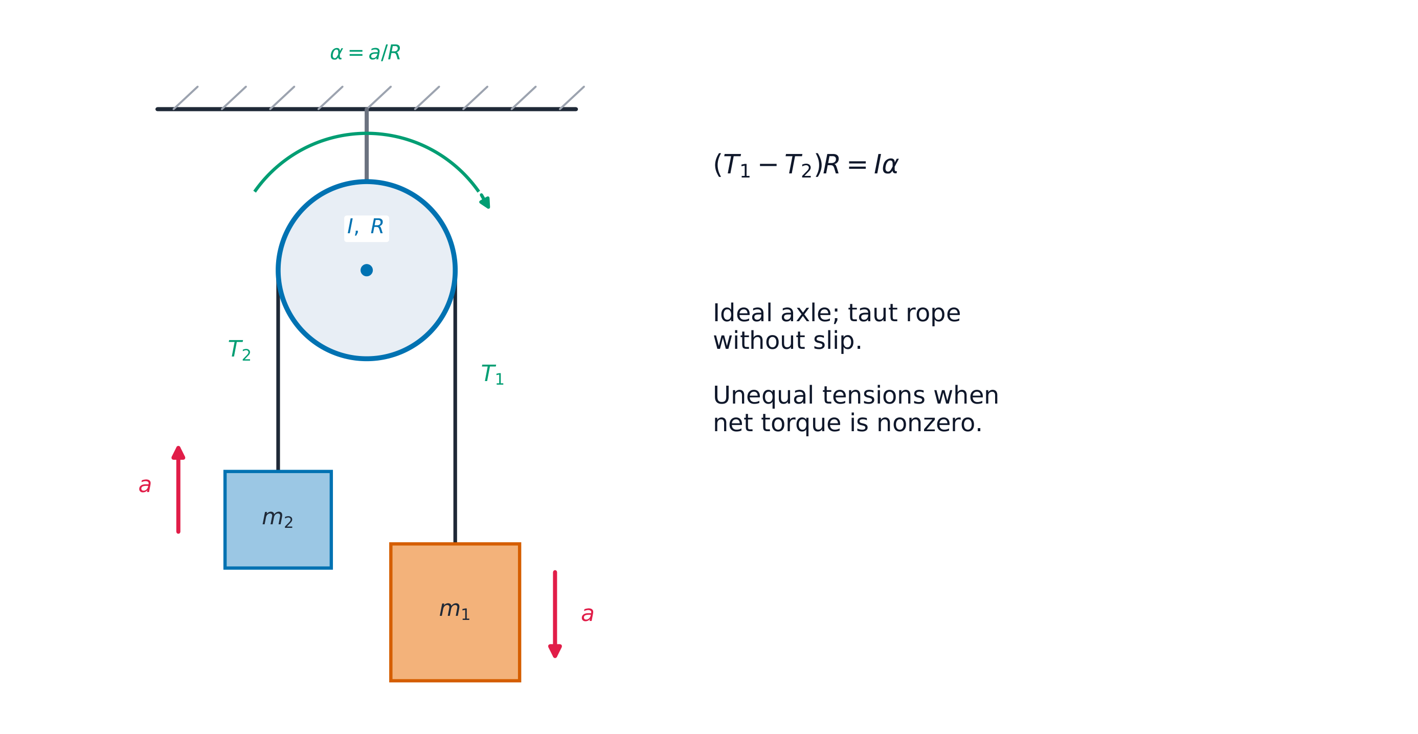
Original massive-pulley task. Masses $m_1=4.0$ kg and $m_2=2.0$ kg hang from a light inextensible rope over a pulley 滑轮 with $I=0.50$ kg m² and $R=0.20$ m. The axle has negligible friction, the rope remains taut and does not slip, and $m_1$ accelerates downward. Use down positive for $m_1$, up positive for $m_2$ and clockwise positive for the pulley. Draw each body's forces separately. The pulley has downward rope forces at opposite rims, its weight at the centre and an axle reaction; the last two give zero torque about its centre.
$$m_1g-T_1=m_1a,\qquad T_2-m_2g=m_2a.$$
$$\sum\tau=(T_1-T_2)R=I\alpha,\qquad a=R\alpha.$$
$$a=\frac{(m_1-m_2)g}{m_1+m_2+I/R^2}.$$
Here $I/R^2=12.5$ kg, so $a=19.6/18.5=1.059\ldots$ m/s², $T_1=m_1(g-a)=34.96\ldots$ N and $T_2=m_2(g+a)=21.72\ldots$ N. Keep unrounded $a$ until the tensions are found. The acceleration is less than the ideal massless-pulley value $3.27$ m/s². For this model, $T_1-T_2=Ia/R^2>0$. A massive pulley at zero angular acceleration can have equal tensions; finite inertia alone does not prove unequal tension. Axle friction would add a torque term.
Vocabulary
Train
| English |
|---|
| pulley/ˈpʊli/ |
5.6
Exam tips
Choose the axis, object/system and signs before writing equations. Use initial conditions with integrals, and constant-acceleration formulas only when justified. For inertia, state $dm$, the perpendicular distance and integration limits; use the centre-of-mass axis correctly in the parallel-axis theorem. For combined translation and rotation, write separate laws and the no-slip constraint before eliminating unknowns. Read the actual exam demand; a universal free-body-diagram or full-mark checklist is not a substitute for its prompt.
Interactive lessons on this topic
Work through it step by step, with instant-check exercises.